In Bambu Studio, you can set some advanced parameters related to print quality in Process > Quality > Advanced.
Please note that some parameters will only be displayed if you enable “Developer mode” in Preferences.
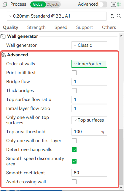
¶ Order of Walls
This parameter is used to adjust the print order of walls. There are currently three options, inner/outer, outer/inner and inner wall/outer wall/inner wall.

¶ Inner/outer
The printer prints from the inside to the outside, that is, the innermost wall first, and the outer wall in the end. This is also the default order, as shown below.
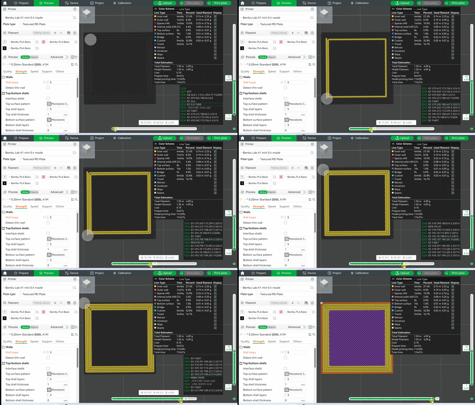
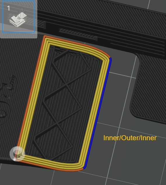
If the model has overhangs, this order will provide better print quality. Because there is a printed inner wall on a side of the outer wall before the printer prints to the overhangs, the inner wall ensures that the overhang adheres and reduces imperfections on the surface caused by warped or collapsed overhangs. The specific differences are shown below.
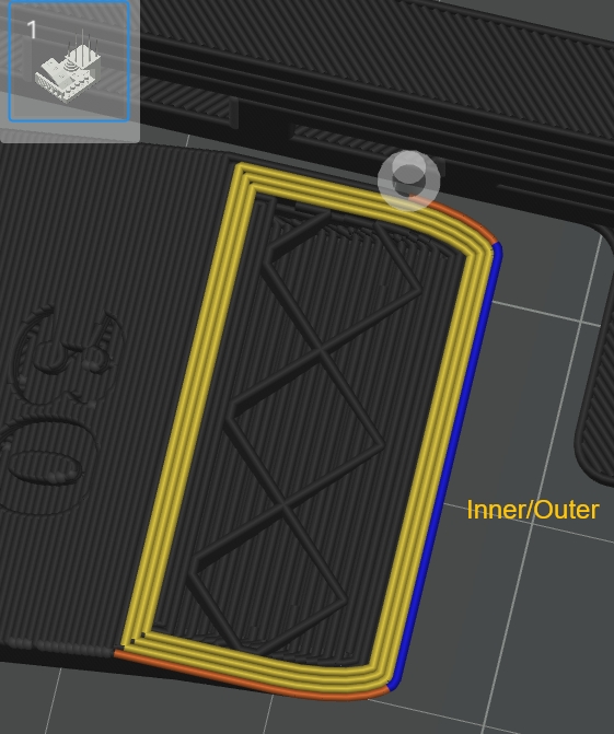
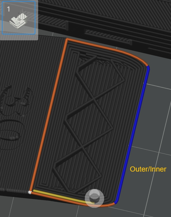
If orders of outer/inner or inner/outer/inner are used, the outer wall (blue lines) is completely overhanging with no adhesion on both sides, resulting in poor overhang quality.
¶ Outer/Inner
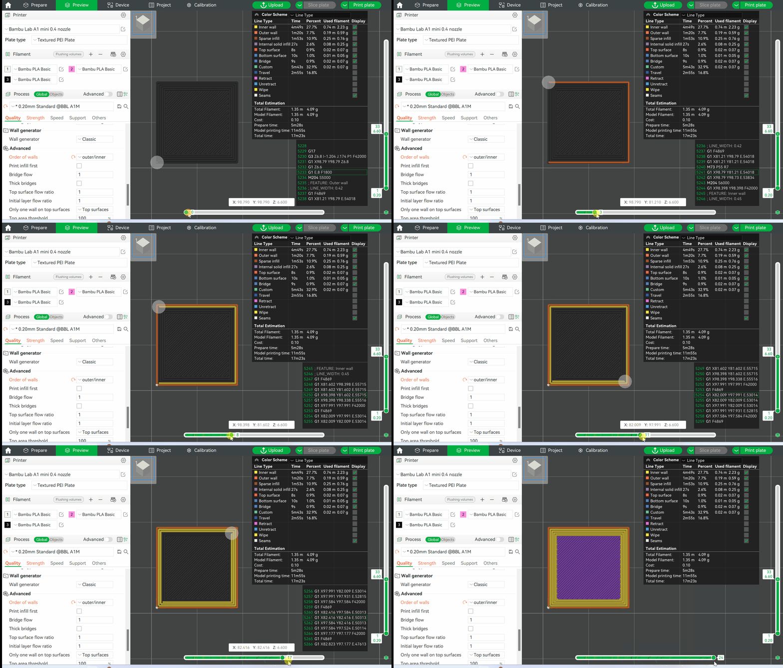
The printer prints from the outside to the inside, that is, the outermost wall first, and the innermost wall in the end. When printing in this order, the seams on the surface of the model may be more obvious. However, if the printer prints the outer walls first, they can cool down and solidify first, which can minimize the imperfections and interlayer patterns on the surface caused by the squeezing or contraction of the lines inside the model.
¶ Inner/Outer/Inner
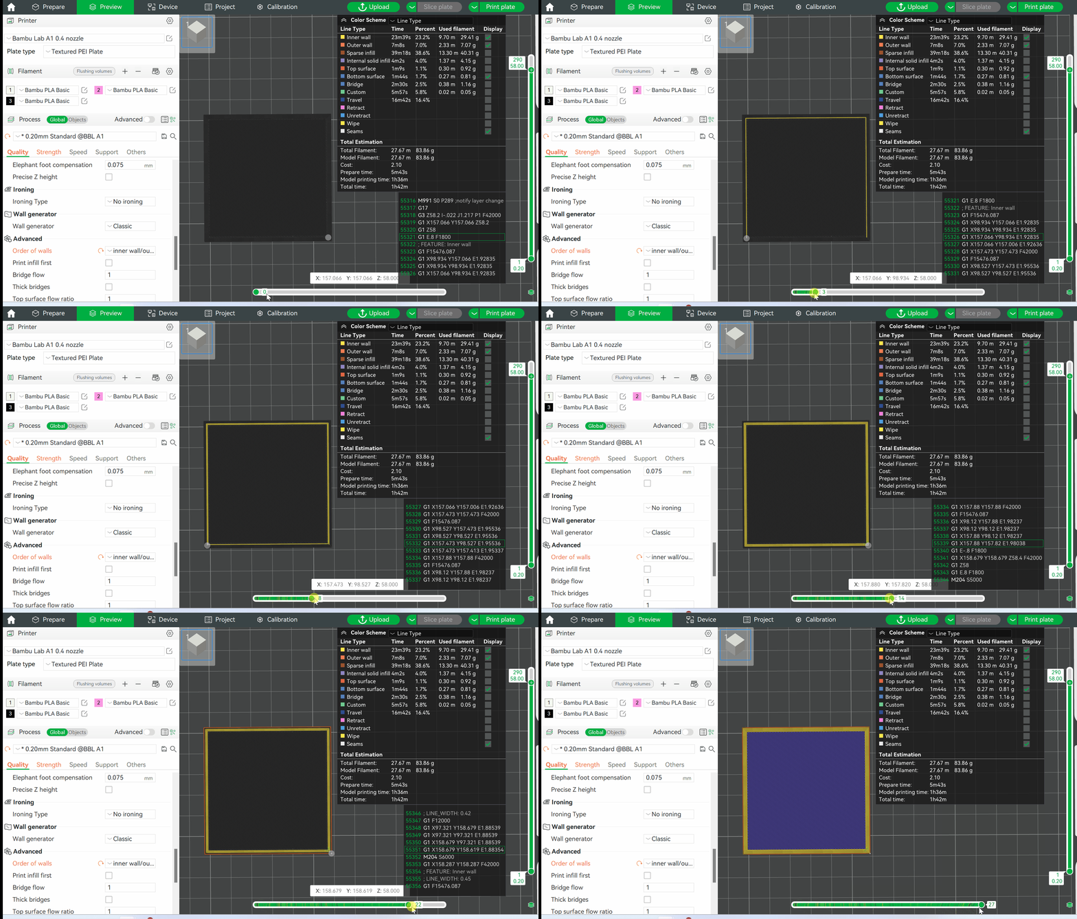
The printer first prints from the innermost wall from the inside out. After printing the second-to-last inner wall, the printer starts printing the outer walls. Finally, the inner wall adjacent to the outer walls are printed, as shown in the following figure.
Printing in this order, there will be an empty space between the outer walls and the other finished inner walls, which minimizes the effect of shrinkage on the inner walls. Moreover, other printed walls have already cooled down and solidified for some time, so they can minimize the squeezing or shrinkage on the inside that affect the outer walls and thus affecting the appearance of the model.
¶ Print infill first
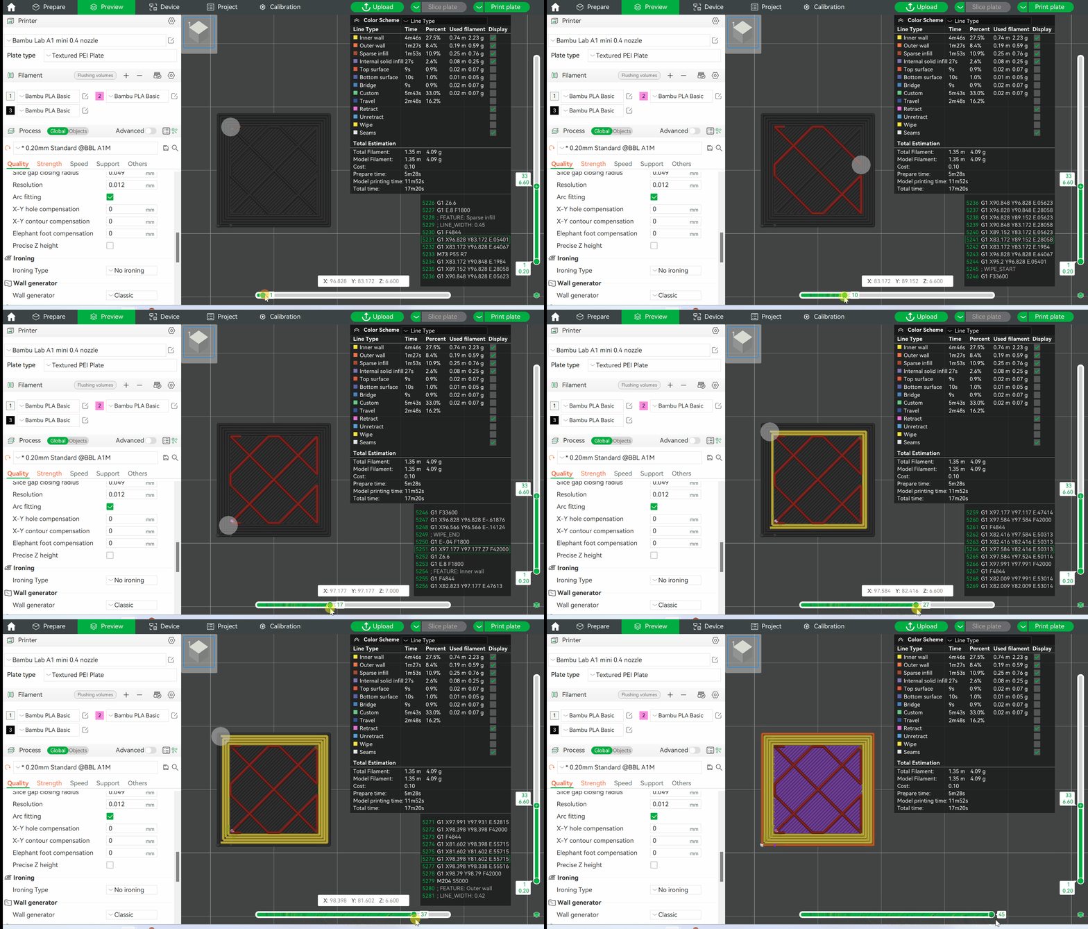
The infill will be printed first, followed by the inner and outer walls. “Infill” here refers to all horizontal lines, including sparse infill, internal solid infill, top surface, bottom surface, and bridge.
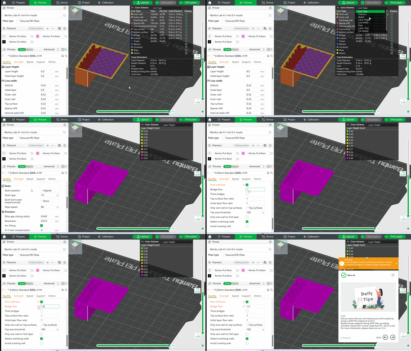
¶ Bridge flow
With this setting on, the actual bridge flow will be calculated by multiplying the original bridge flow by this factor. For details, please refer to: Bridge settings
¶ Thick bridges
Enable thick bridges. For details, please refer to: Bridge settings
¶ Top surface flow ratio
For the top surface, the actual flow ratio is calculated by multiplying the original flow ratio by this factor. This factor affects the amount of filament used for the top solid infill.
¶ Initial layer flow ratio
The actual flow ratio is calculated by multiplying the original flow ratio by this factor.
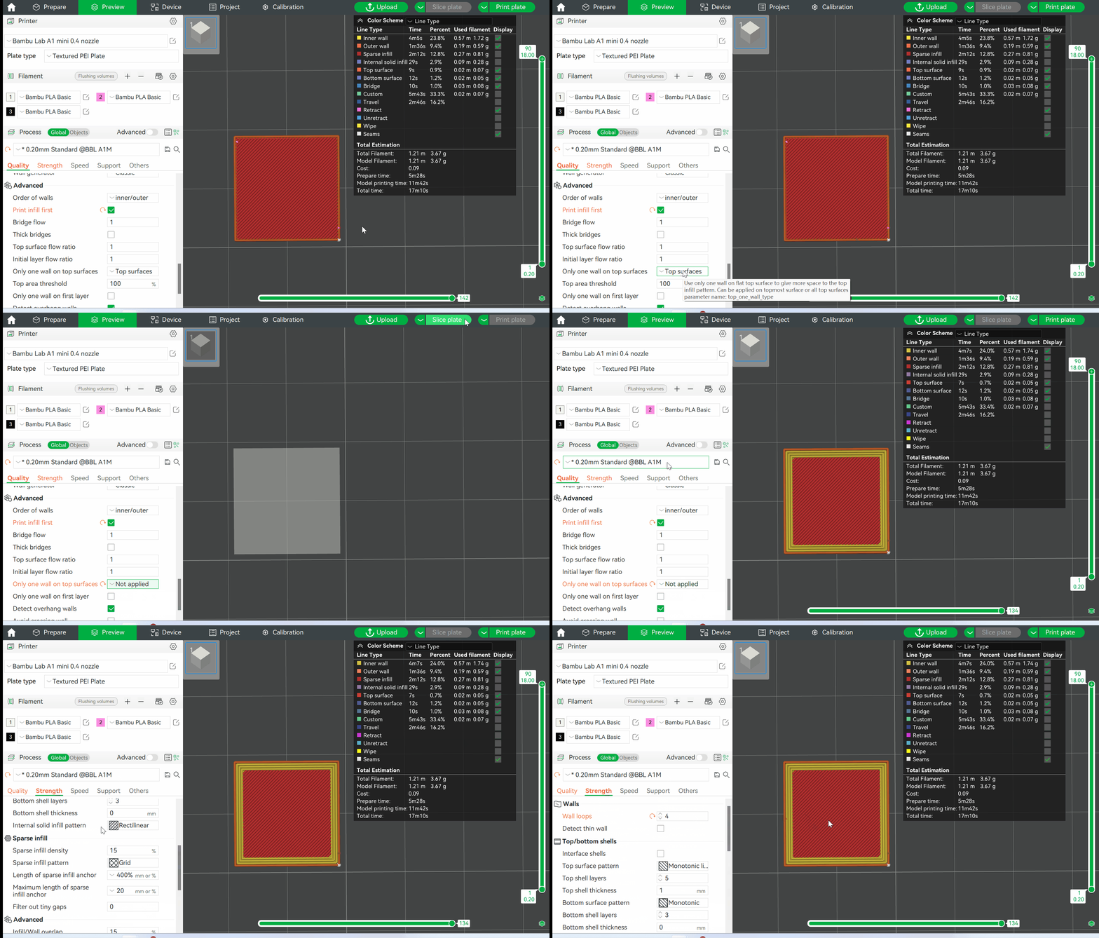
¶ Only one wall on top surfaces
With this option enabled, top surfaces will have only one wall, giving better appearance to top surfaces, especially for models with a flat top. This option is enabled by default. If you disable this option, the number of walls on top surfaces will be the same as the number of wall loops set in Strength > Walls.
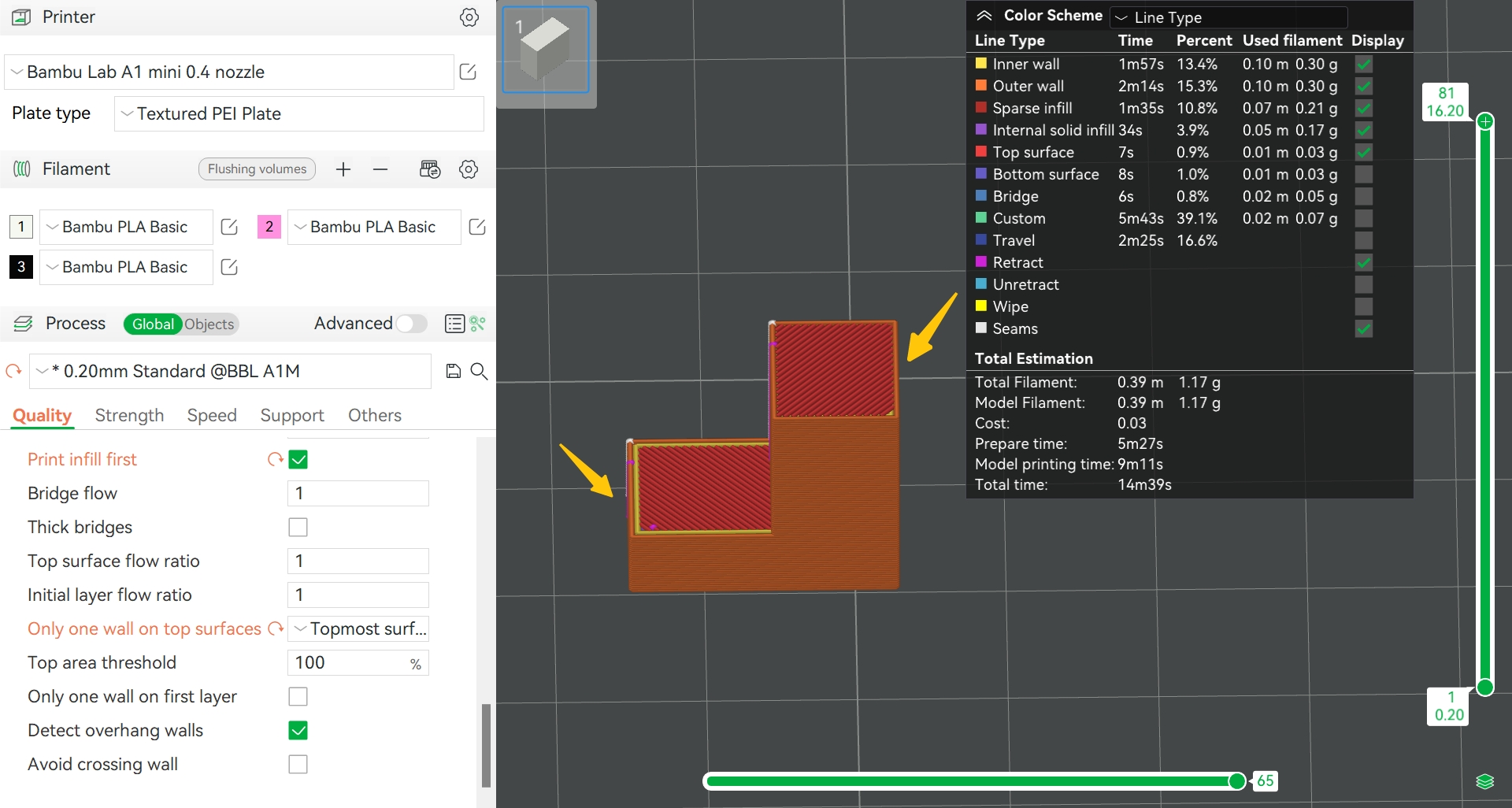
This option can work on both the top surface and the topmost surface. The top surface refers to all top surfaces of the model, and the topmost surface refers to the highest one of the object, as shown below.

¶ Top area threshold
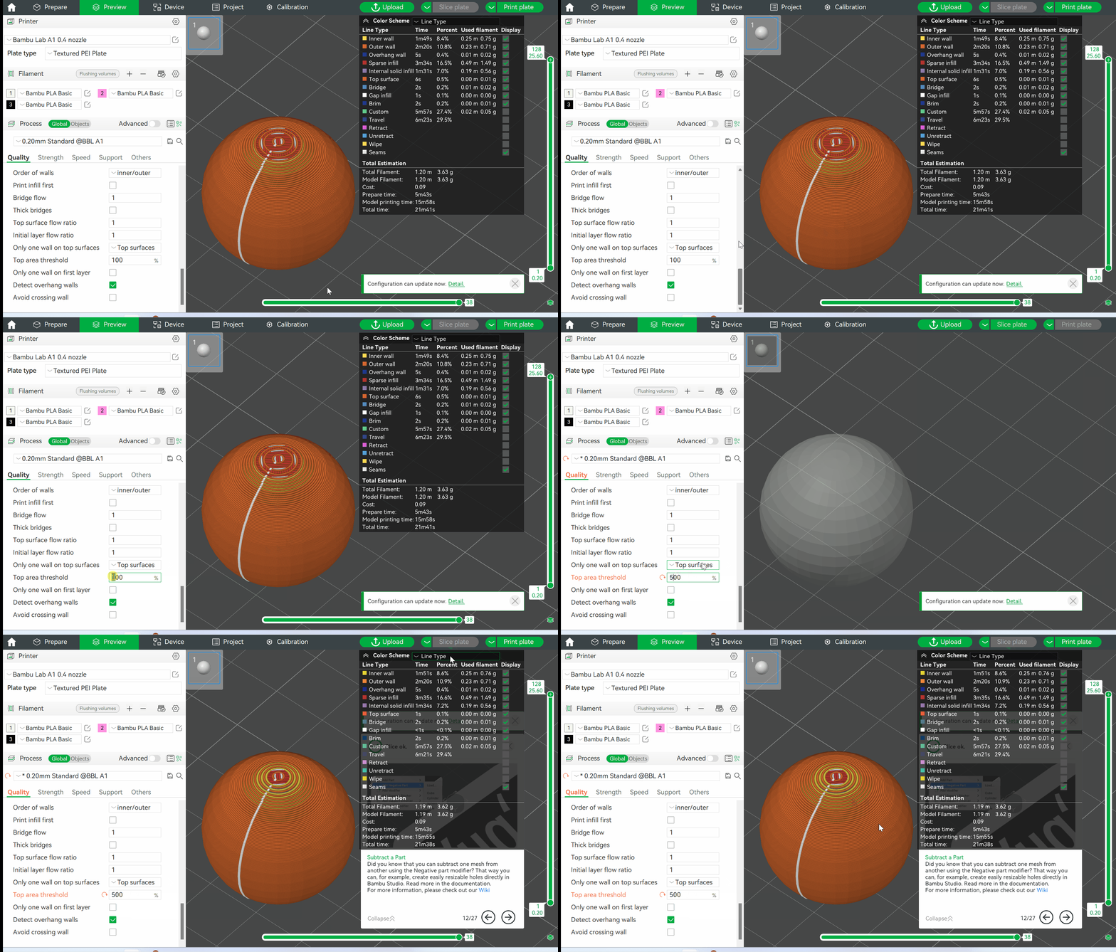
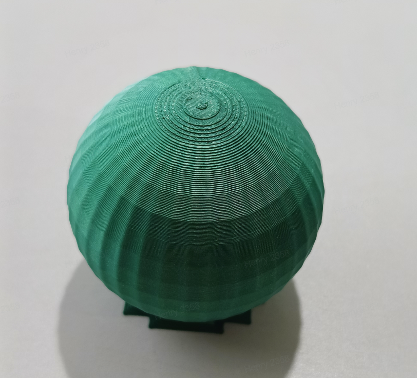
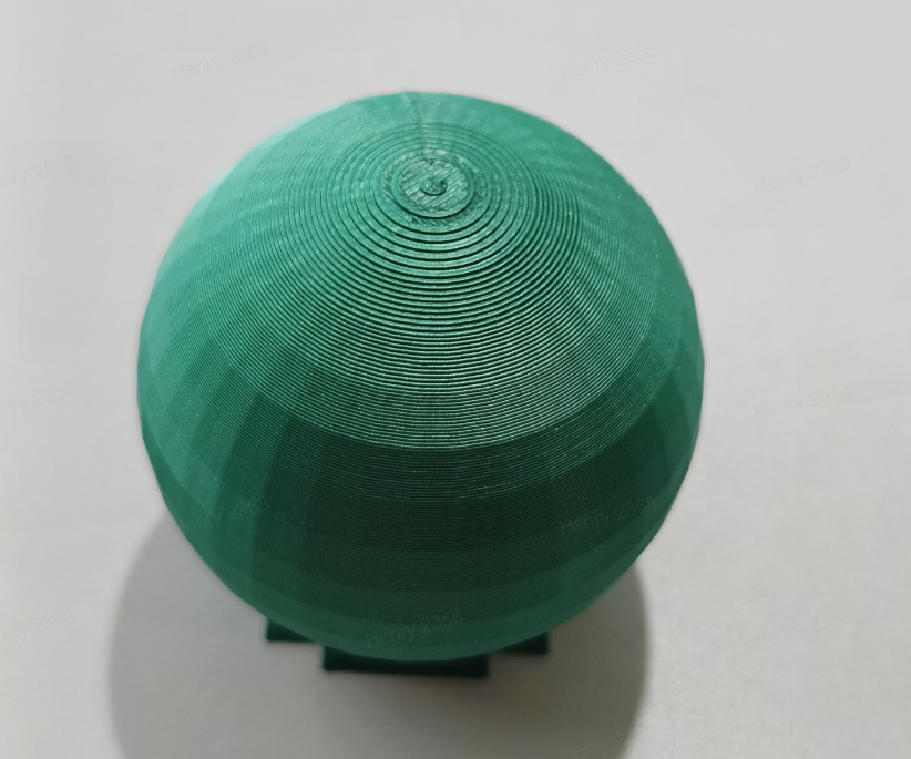
This parameter can be configured after only one wall on top surfaces is enabled. This parameter affects the area threshold for the area of the wall that forms a single layer of the top surface. If part of the top surface is covered by a higher layer, such as the top of a sphere, then that top surface will not be considered as a top surface if its width is less than this threshold.
This can be used to avoid triggering “only one wall on top surface” on narrow top surfaces (usually not the topmost surface). This threshold represents the percentage of line width. By increasing this value, smaller top surfaces are filtered out and still generated with the number of walls set in wall loop. However, this threshold does not take effect on the topmost surface.
Adjusting this threshold will provide smoother transition on the surface when printing certain models with curved or sloping surfaces. The specific effect is shown below.
|
Default threshold |
Increased threshold |
|---|---|
 |
 |
¶ Detect overhang walls
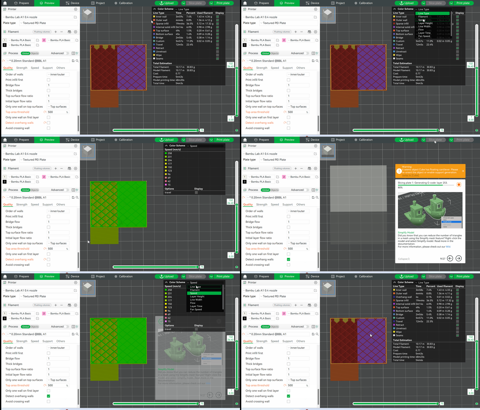
This option detects the overhang angle of walls and applies different printing speeds. For walls with 100% overhang angle, the bridge speed will be applied. For details, please refer to: Slow Down for Overhangs
If this option is disabled, the inner and outer walls will print using the inner and outer wall speeds in the speed settings. The differences are described below:
¶ Smooth speed discontinuity area
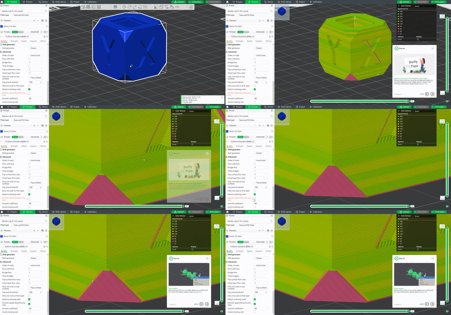
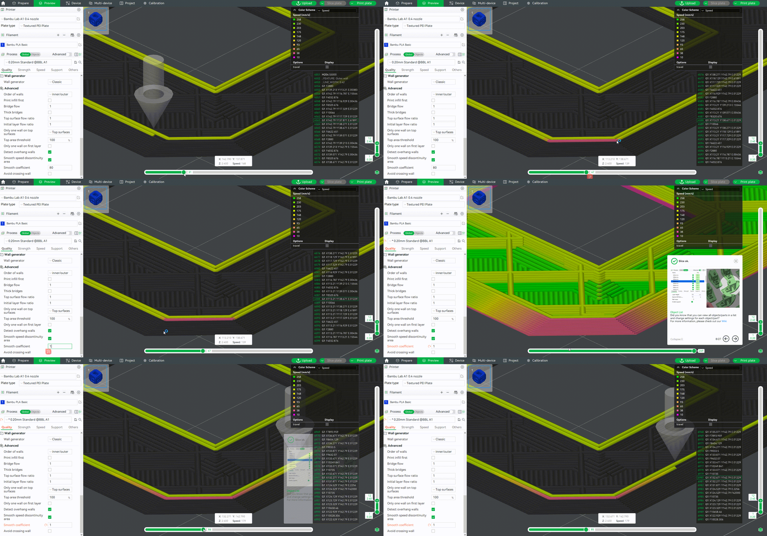
Bambu Studio version 1.9.4 introduces the option to smooth the speed. Overhanging and non-overhanging areas usually have large speed variations, so enabling this option can make speed transitions smoother to improve cooling. This option is enabled by default.
¶ Smooth coefficient
It is used to control the length of the smooth transition path. The smaller the value, the longer the area of the speed transition, which means that the speed transition is smoother. Appropriate adjustment of the smoothing coefficient can make the print quality of the overhang area better, and it is usually recommended to set in the range of 1 to 200.
¶ Avoid crossing wall
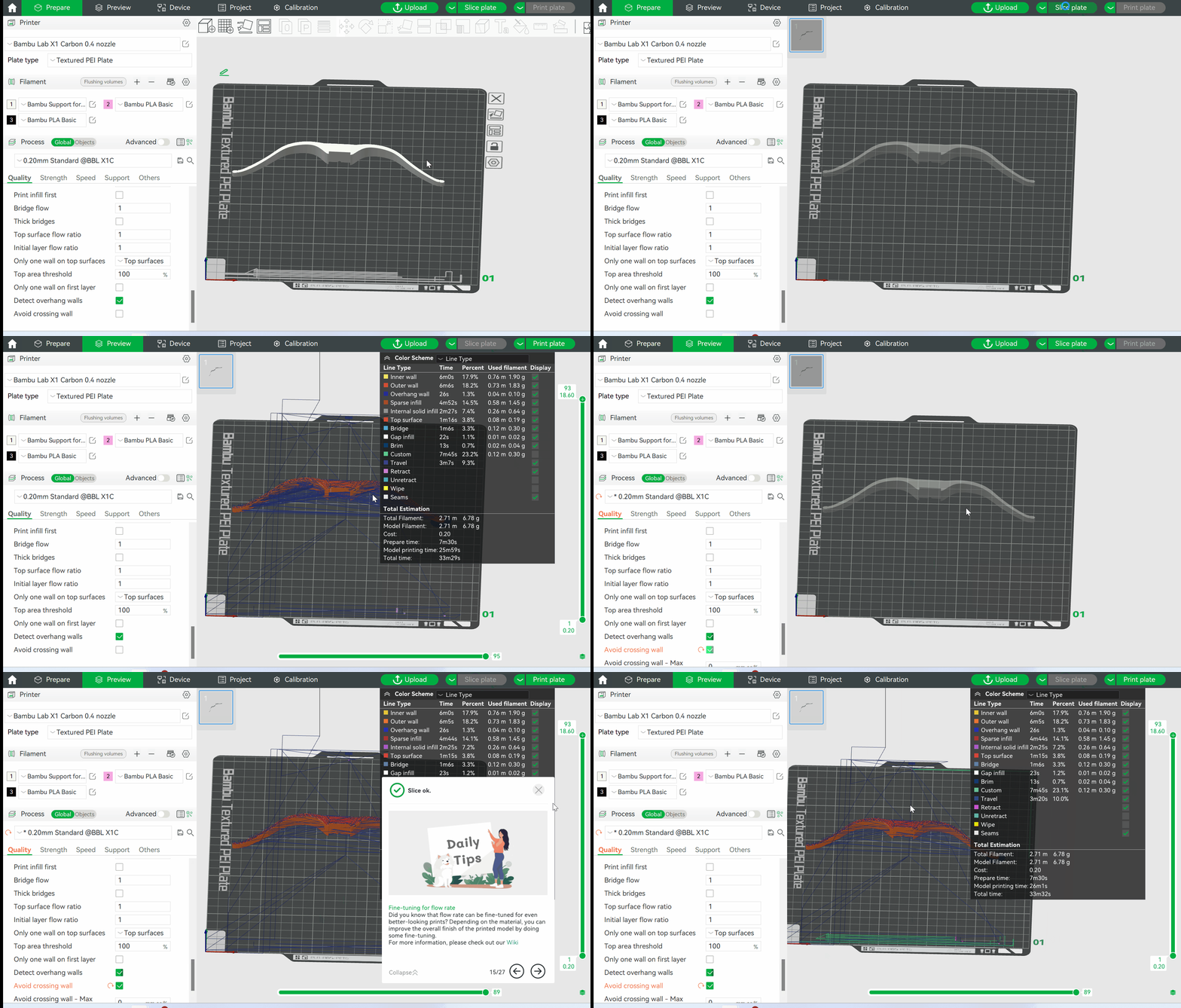
Enabling this function allows the nozzle to not cross the outer wall as much as possible when traveling. This can minimize oozing that leads to stringing when crossing the outer wall when printing a layer print of one object.

Avoid crossing wall - Max detour length: When the detour length of a travel is greater than this value, this travel will not make a detour.
The detour length can be set as an absolute value, or as a percentage relative to the length of a straight travel (50 means 50mm; 50% means a percentage). This value represents the increased length of the detour compared to the normal travel. If the length exceeds the value, the detour will not be made, and the original straight travel will be performed.
Maximum detour length is 0 by default, representing no limit on the detour length, and all detours will be performed. The path of a travel will follow along the contour of a layer, but the detour will only be taken if the start and end points are both inside or outside the wall. If one is outside the wall and one is inside the wall, no detour can be taken.
The specific effect is shown in the figure below. You can see that enabling this option greatly reduces travels between walls.
¶ End Notes
We hope the detailed guide provided has been helpful and informative.
To ensure a safe and effective execution, if you have any concerns or questions about the process described in this article, we recommend submitting a technical ticket regarding your issue. Please include a picture or video illustrating the problem, as well as any additional information related to your inquiry.