¶ Z-axis lead screw assembly
The Z-axis lead screw assembly for X/P series printers includes a lead screw, lead screw nut, bearing (top of lead screw), bearing (bottom of lead screw), and screw.
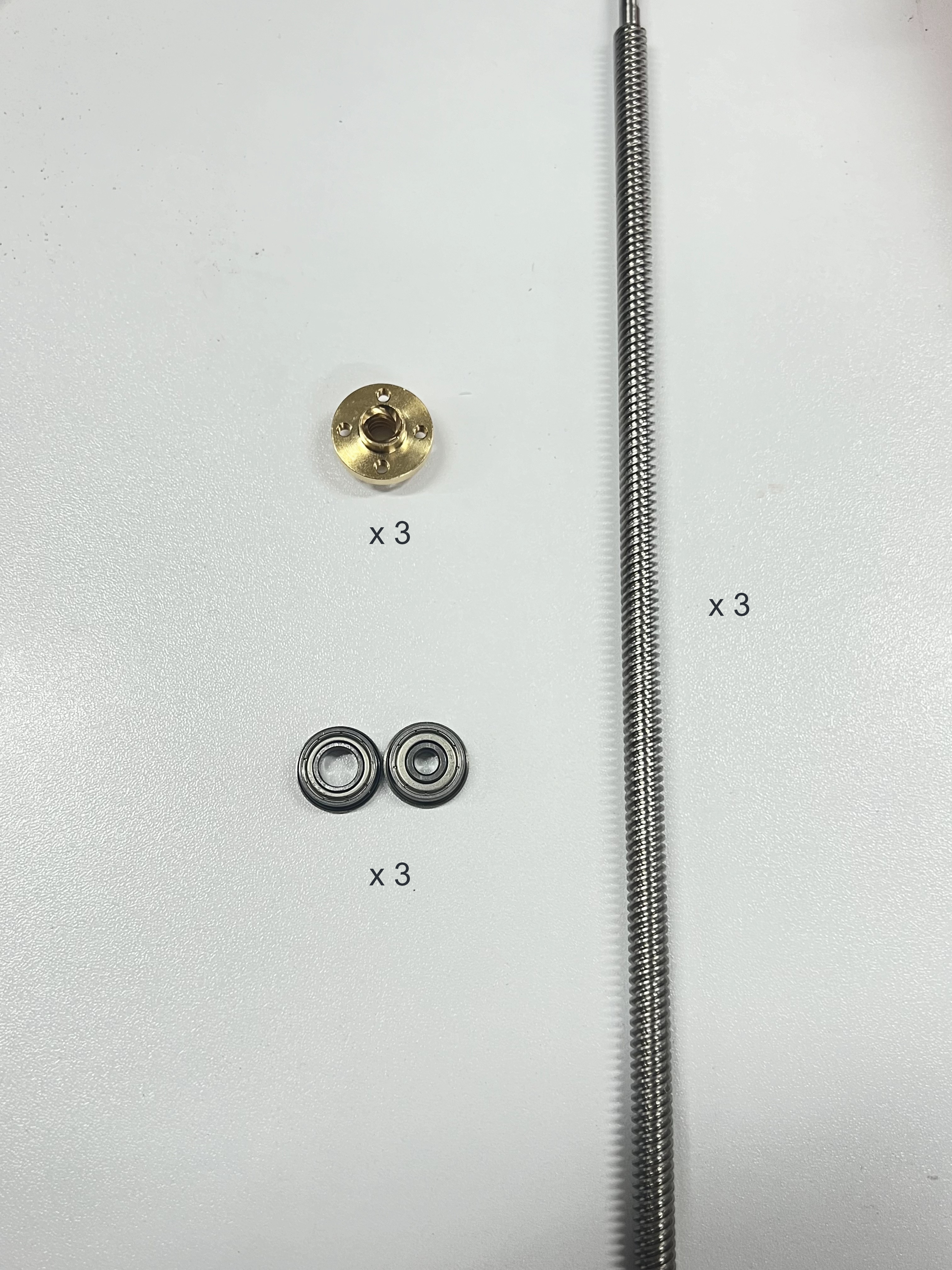
There are 3 lead screws on the X/P printer. The 2 lead screws near the front door pillar are disassembled and assembled in the same way. This guide takes the disassembly and assembly of the left lead screw as an example.
The lead screw near the back of the printer is blocked by the liner, so the liner screws need to be loosened before disassembly and assembly.
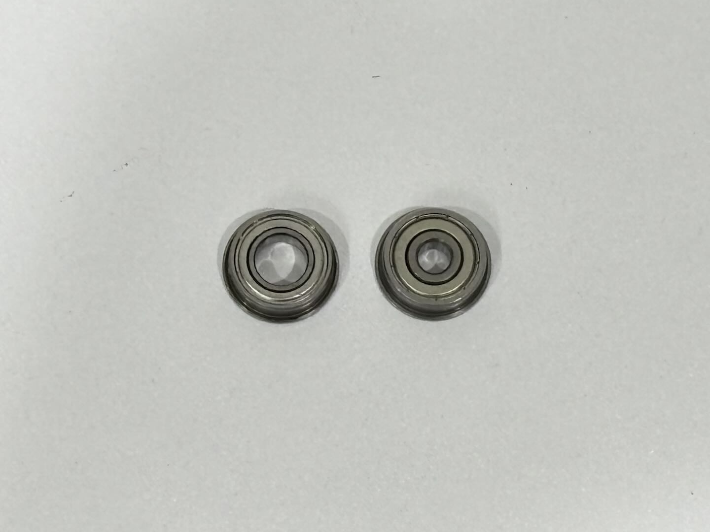
The inner diameters of the top/bottom bearings are different, and the inner diameter of the top bearing is larger than that of the bottom bearing (the left side of the figure below is the top bearing, and the right side is the bottom bearing):
¶ Applicable models of printers
X1C/P1P/P1S/X1E
¶ When to use?
- The threaded rod is deformed.
- The lead screw nut is worn.
- The bearing is damaged.
¶ Safety Warning
IMPORTANT!
It's crucial to power off the printer before conducting any maintenance work, including work on the printer's electronics and tool head wires. Performing tasks with the printer on can result in a short circuit, leading to electronic damage and safety hazards.
During maintenance or troubleshooting, you may need to disassemble parts, including the hotend. This exposes wires and electrical components that could short circuit if they contact each other, other metal, or electronic components while the printer is still on. This can result in damage to the printer's electronics and additional issues.
Therefore, it's crucial to turn off the printer and disconnect it from the power source before conducting any maintenance. This prevents short circuits or damage to the printer's electronics, ensuring safe and effective maintenance. For any concerns or questions about following this guide, open a new ticket in our Support Page and we will do our best to respond promptly and provide the assistance you need.
¶ Tools and materials needed
- Z-axis lead screw assembly (If you need to replace it, please submit a technical ticket)
- H2.0 Allen key
- BT3-28-15 screw - for fixing the heatbed * 3
¶ Remove the Z-axis lead screws on both sides of the front door pillars
This guide uses P1P as an example to demonstrate how to replace the lead screw on the left side of the front door pillar. The lead screw on the right side can be replaced in the same way.
¶ Step 1: Remove the lead screw nut fixing screws
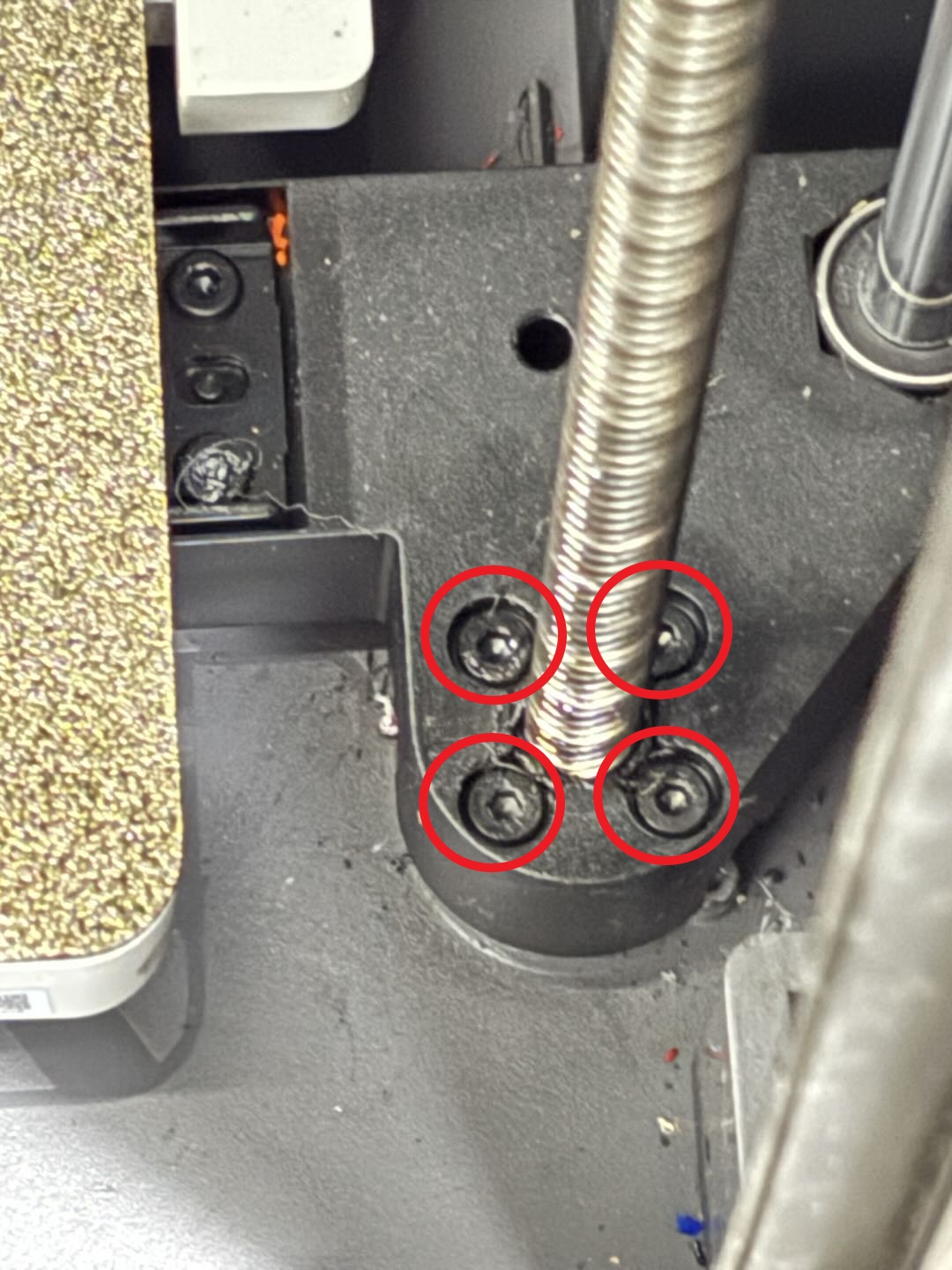
Use an H2.0 Allen key to remove the 4 lead screw nut fixing screws;
¶ Step 2: Remove the bottom bearing fixing screws
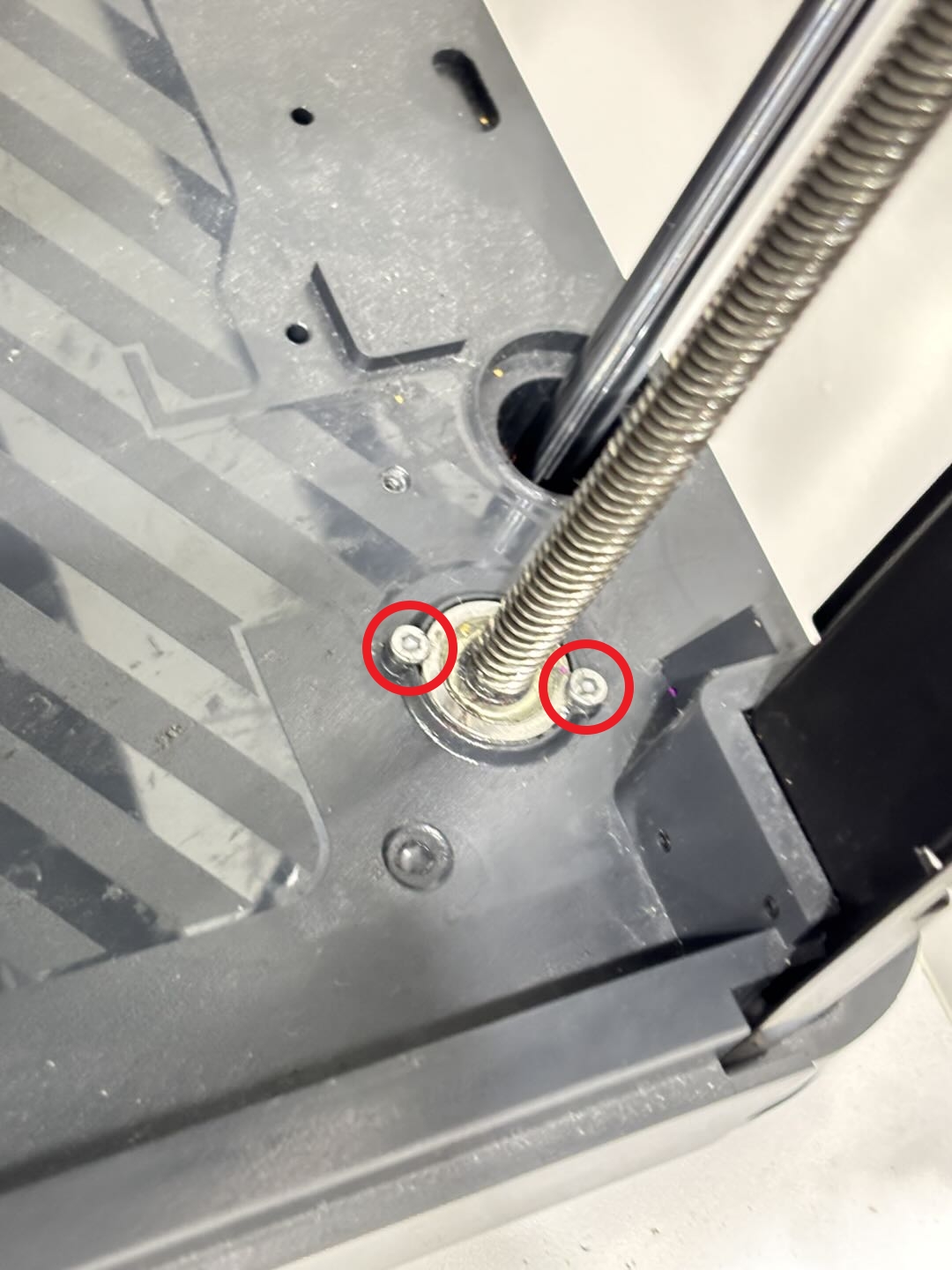
Use an H2.0 Allen key to remove the 2 bottom bearing fixing screws;
¶ Step 3: Remove the Z belt timing pulley/Z belt
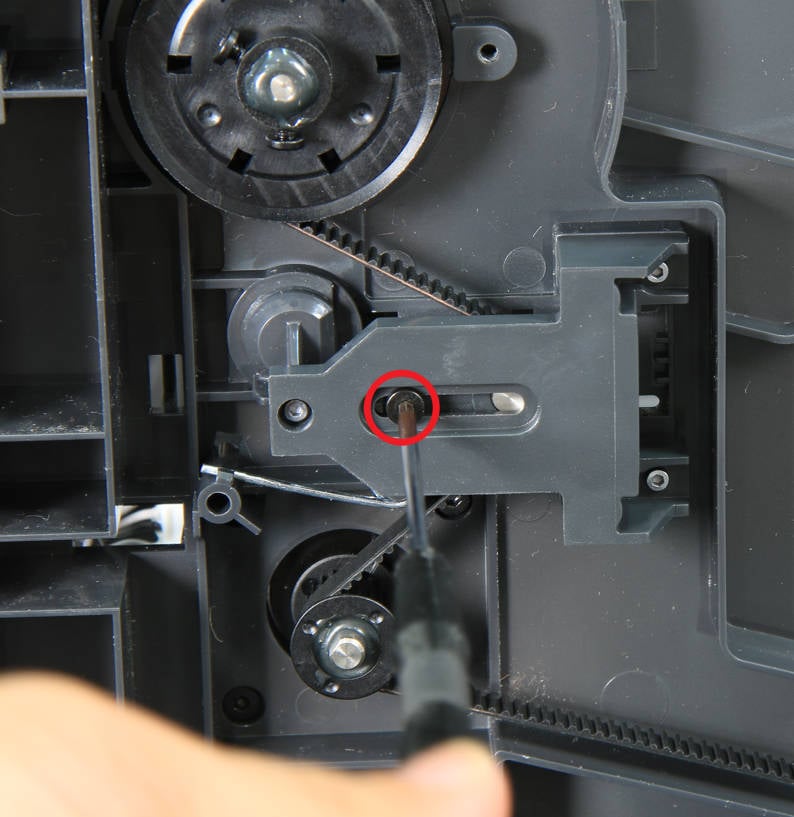
Lay the printer on its side, use an H2.0 Allen key to loosen one of the Z-axis tensioner fixing screws and release the torsion spring, then remove the Z belt from the timing pulley.
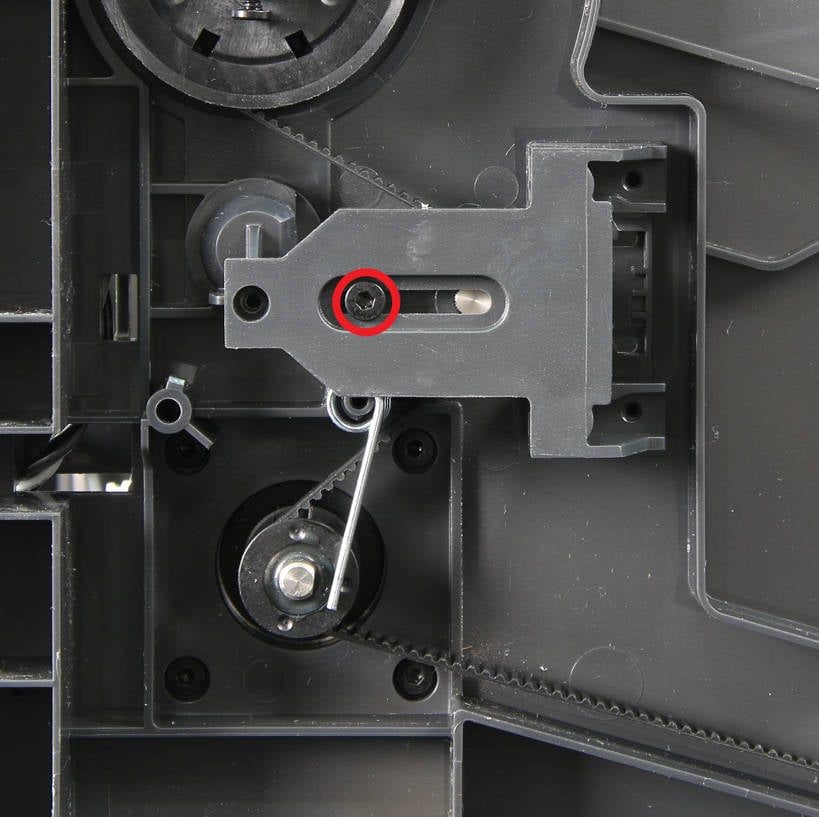
Use an H2.0 Allen key to remove the 2 timing pulley fixing screws, and then use a scraper to scrape off the AB glue between the timing pulley and the lead screw;
Note: Be careful when using a scraper to remove the AB glue to avoid scratching.
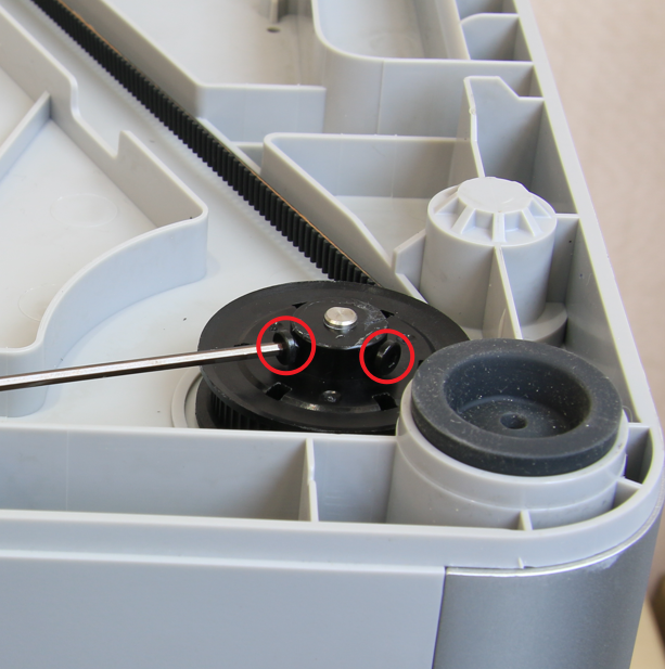 |
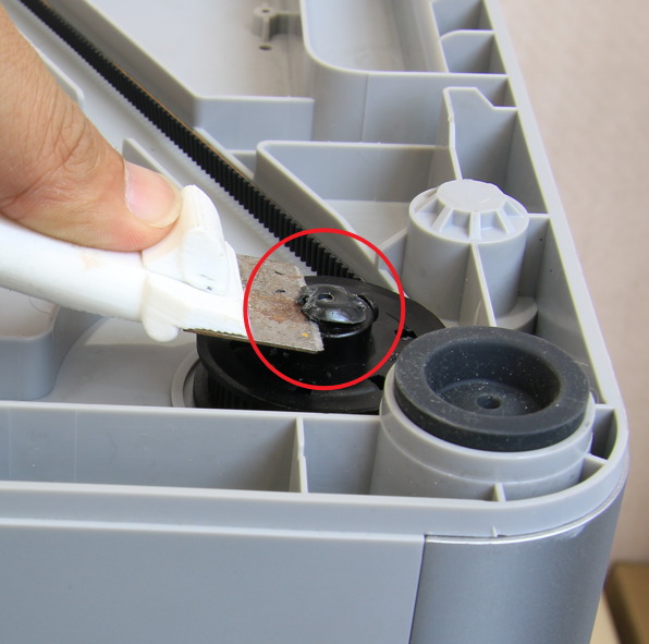 |
Then move the heatbed to the bottom (after the printer is turned upside down), then hold the Z belt timing pulley, lift up and remove it.
¶ Step 4: Remove Z-axis lead screw/bearing
Use an H2.0 Allen key to hold the bottom of the threaded rod and then forcefully knock the threaded rod out.
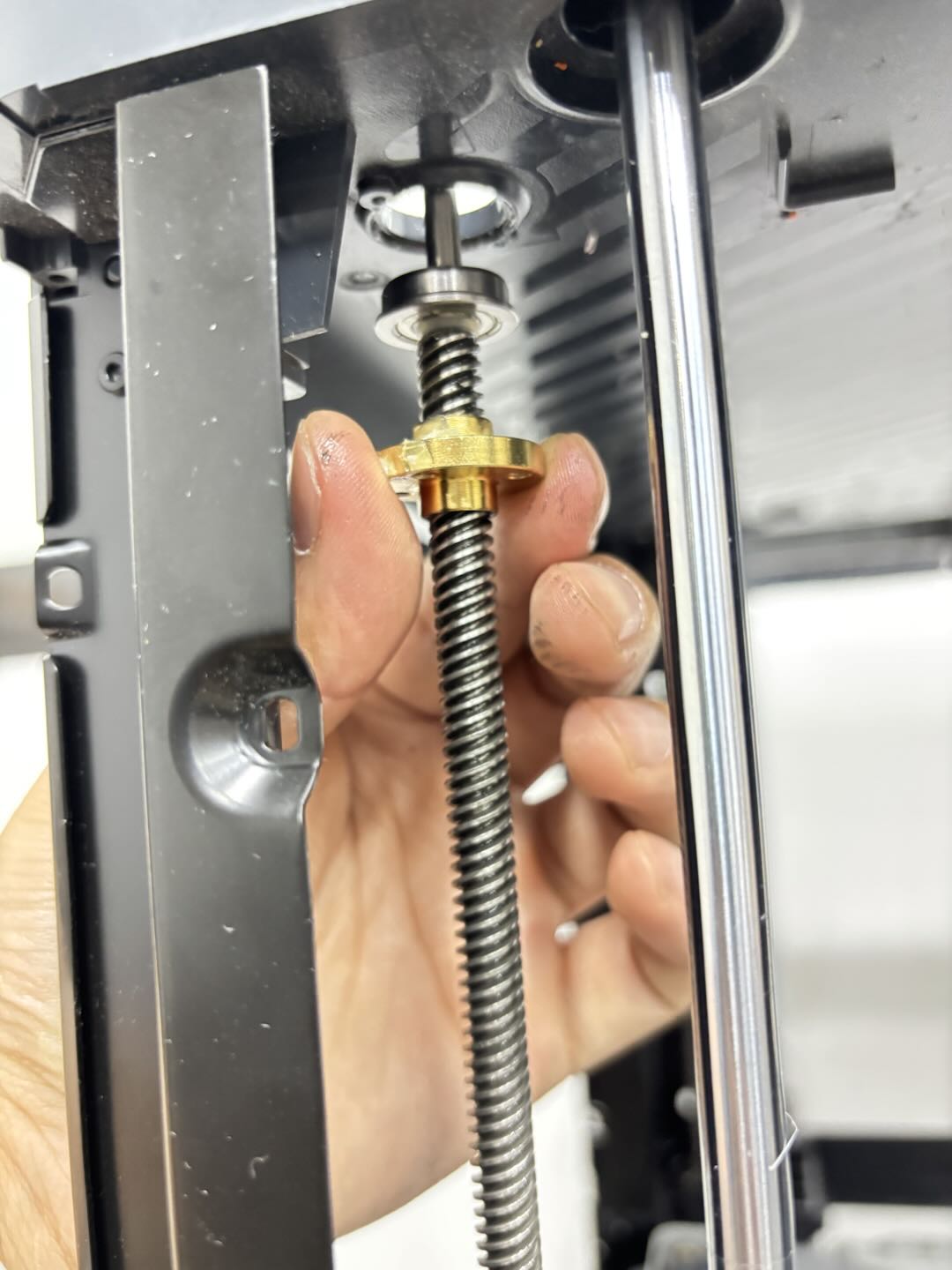
Then remove the top bearing and silicone sleeve from the lead screw. If the bottom bearing remains on the printer base, knock it out with an Allen key; if it is removed together with the lead screw, remove the bearing from the lead screw.
Note: If the bearing is damaged, you can use the bearing included in the assembly.
¶ Install the Z-axis lead screws on both sides of the front door pillars
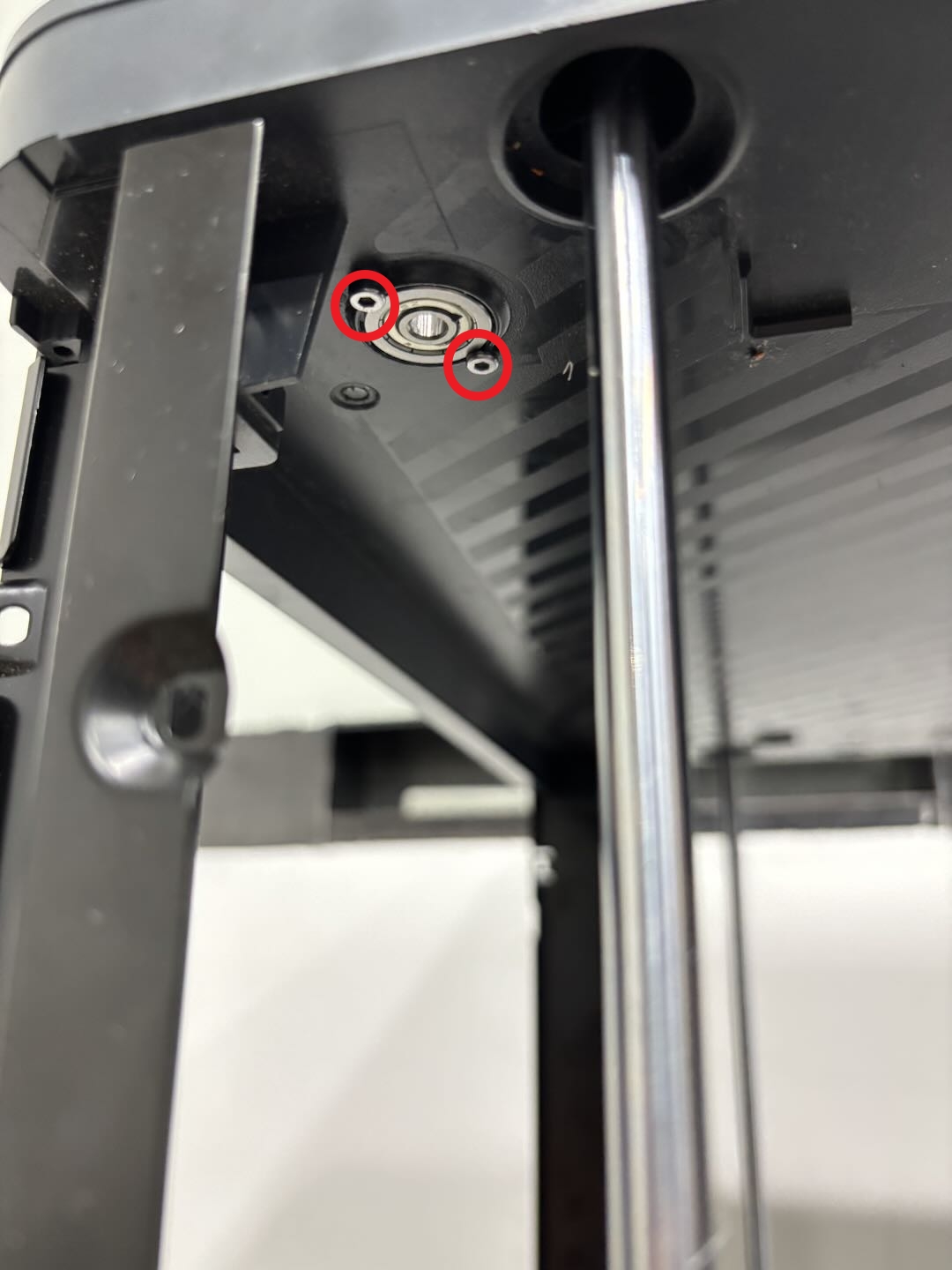
¶ Step 1: Install the bearing
Install the bearing at the bottom of the printer to the corresponding hole, and then tighten the 2 fixing screws with an H2.0 Allen key;
¶ Step 2: Install the lead screw and timing pulley
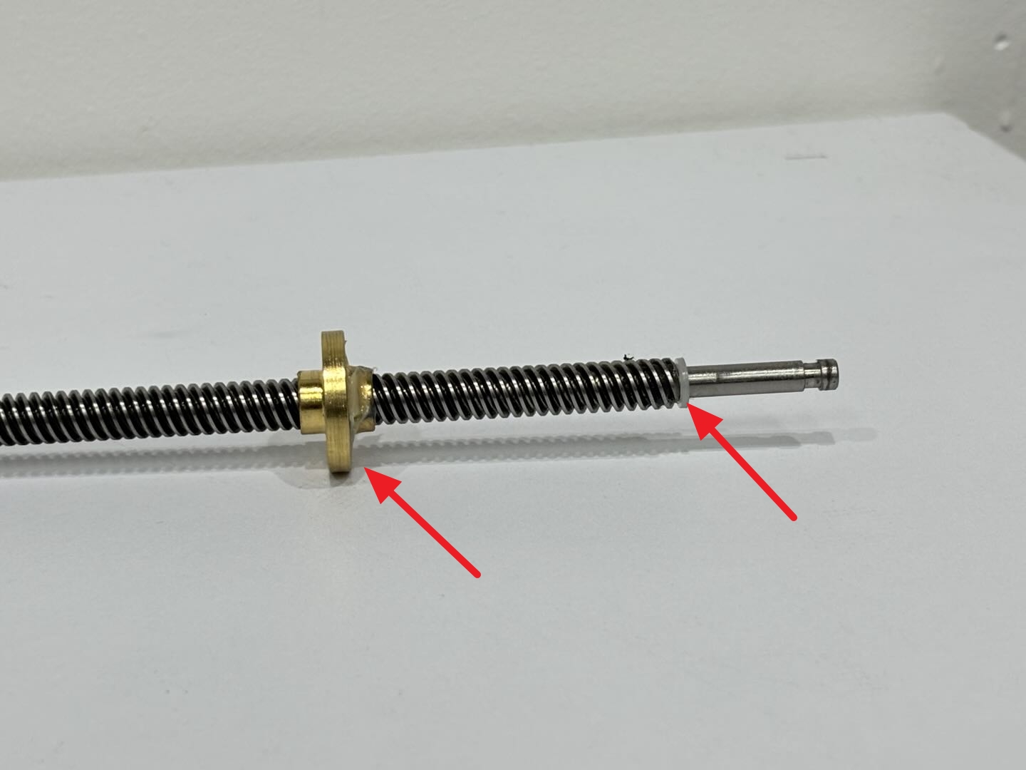
Install the lead screw nut into the lead screw first, then install the plastic washer to the bottom of the lead screw, and then insert the lead screw into the Z-axis slider first, and then insert the lead screw into the bearing.
 |
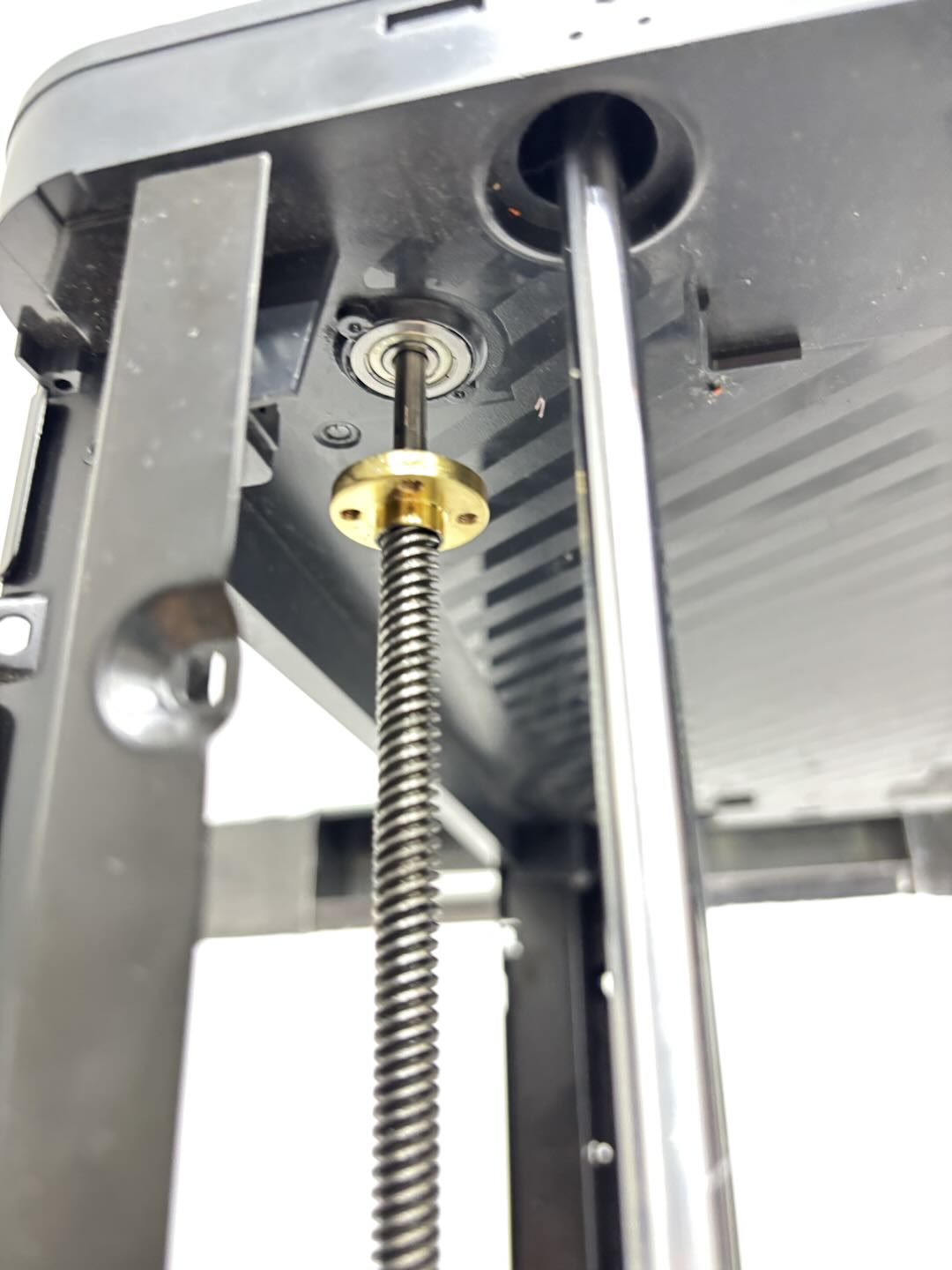 |
It is recommended to hold the lead screw with your hands to prevent it from falling;
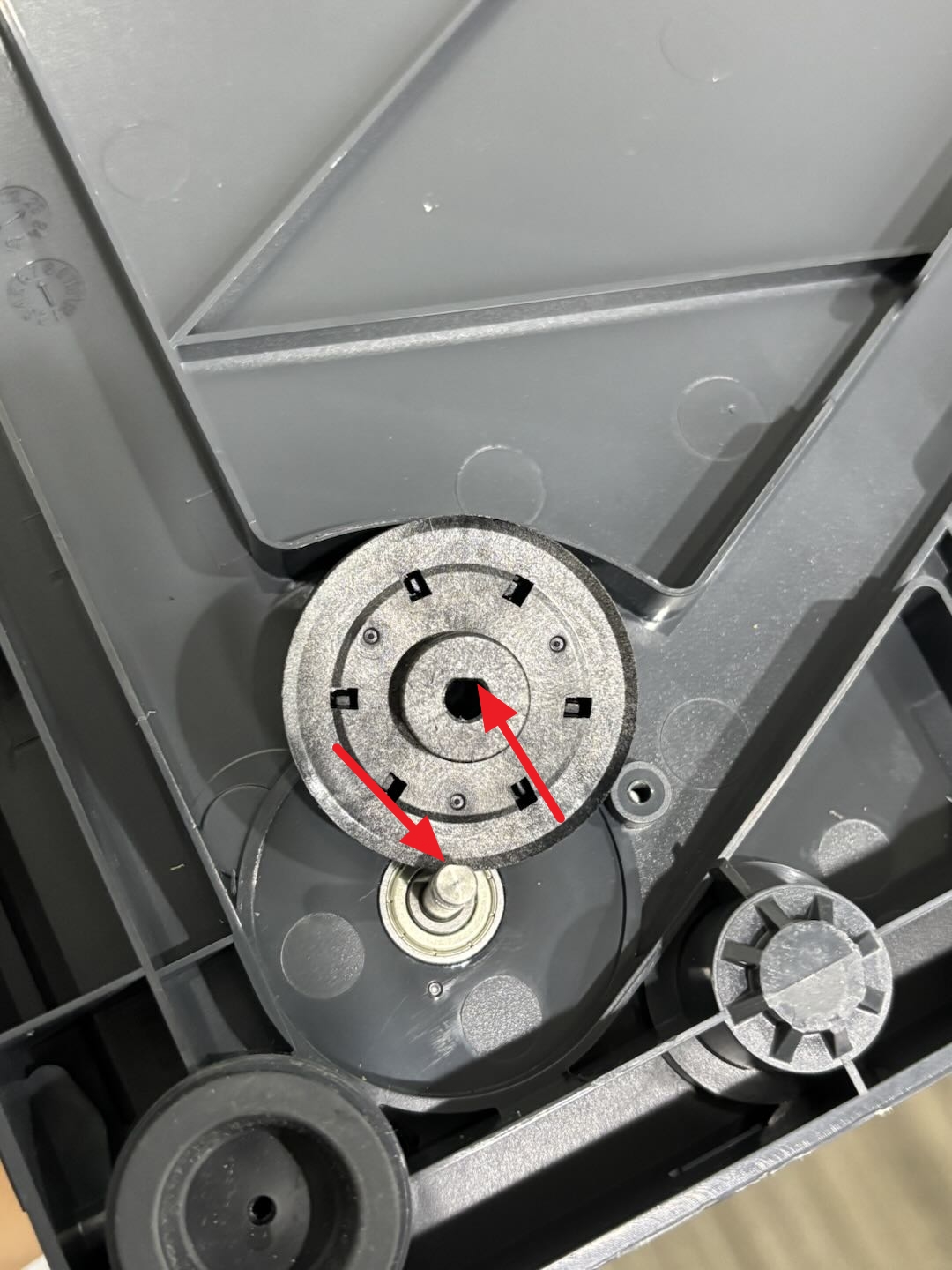
Then align the surface on the Z belt timing pulley with the surface of the lead screw, insert the timing pulley into the screw, and tighten the 2 fixing screws with an H2.0 Allen key;
 |
 |
¶ Step 3: Fix the heatbed
Place the printer upright, first check if there is any foreign matter at the bottom of the printer, then lower the heatbed to the bottom of the printer (the heatbed will be automatically lowered to the bottom after the printer is turned over), and tighten the 3 fixing screws (BT3 x 28 x 15) using H2.0 Allen key.
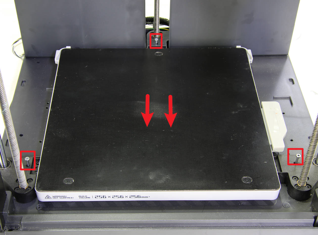
You can use the screws that secured the heated bed during unboxing. If lost, you can use screws of the same specification (BT3x28x15, thread length 15mm), or purchase screws of this specification from the official Bambu Lab store.
¶ Step 4: Tighten the lead screw nut and fix the screw
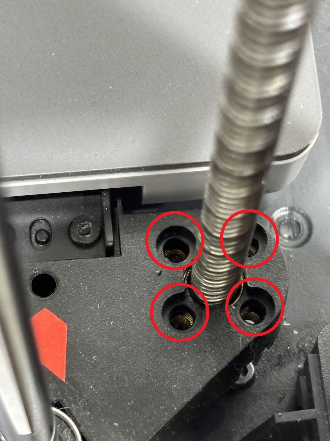
Use an H2.0 Allen key to tighten the 4 screws.
 |
 |
If the screw hole of the lead screw nut is not completely aligned with the hole on the Z-axis slider, please check whether the heatbed fixing screws in step 3 are fully screwed in place and whether there are foreign objects at the bottom of the heatbed. If screws are already tightened, you can try to manually turn the bottom timing pulley to align the screw holes.
¶ Step 5: Install the Z belt
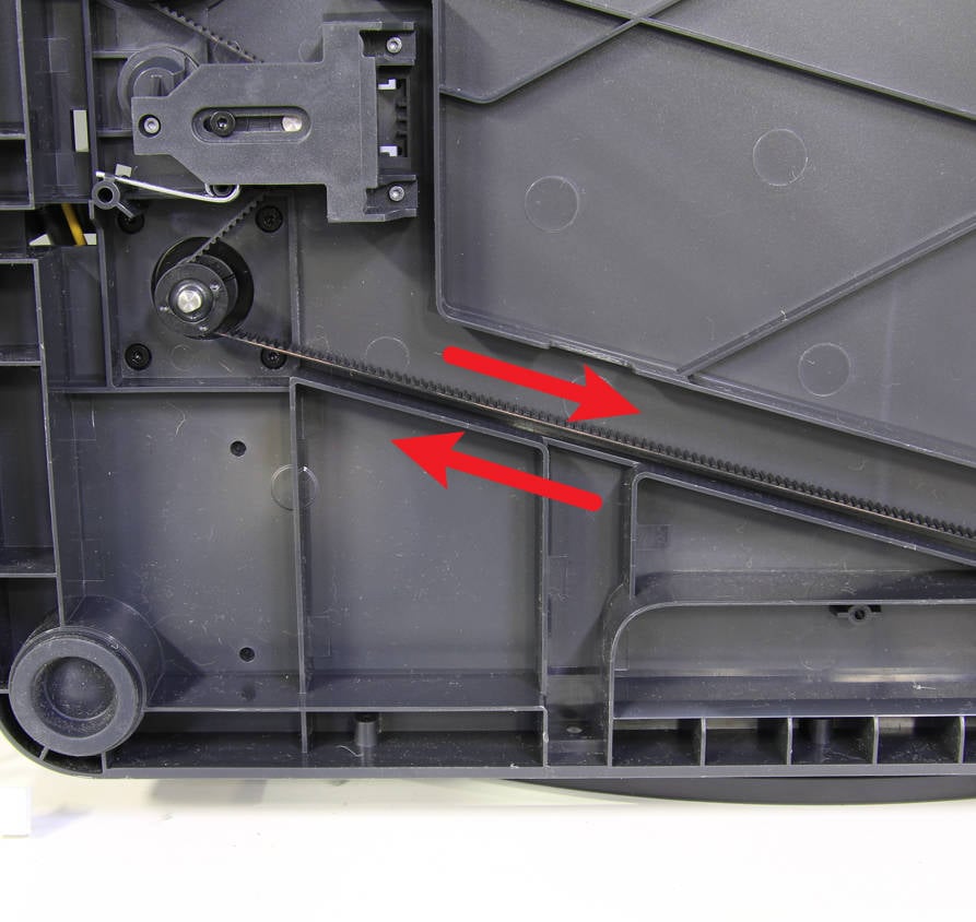
Lay the printer on its side, rewind the Z belt around the Z-axis timing pulley and the Z motor, and then buckle the torsion spring back;
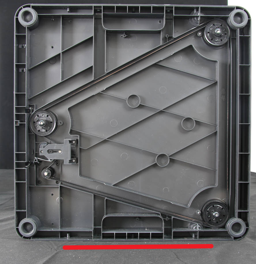
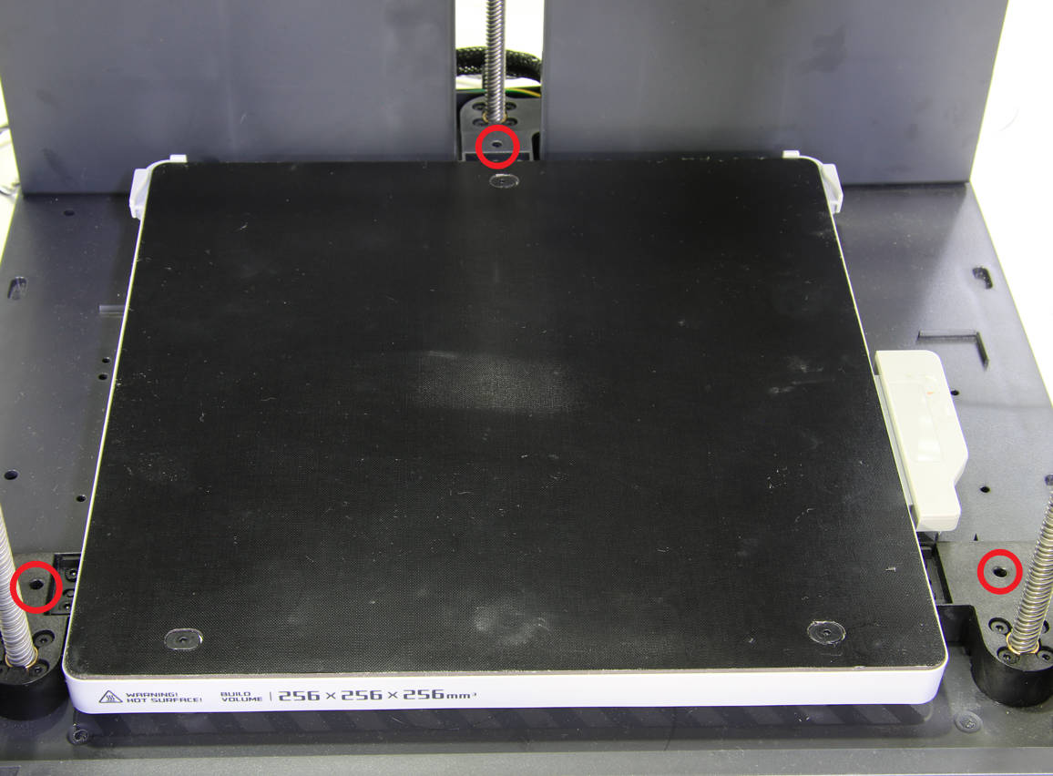
Then use an H2.0 Allen key to remove the 3 heatbed fixing screws, unlock the heatbed, manually pull the Z belt back and forth several times, and then tighten the Z tensioner screw with an H2.0 Allen key.
 |
 |
 |
¶ Step 6: Install the top bearing and silicone sleeve
Press the bearing into the top of the screw and then fit the silicone sleeve into place.
¶ Remove the lead screw from the back of the printer
This guide uses P1P as an example to demonstrate how to replace the lead screw on the back of the printer.
¶ Step 1: Remove the printer rear panel
You can refer to the corresponding Wiki to remove the rear panel according to the printer series:
¶ Step 2: Remove the lead screw nut fixing screws and bearing fixing screws
Use an H2.0 Allen key to remove the 4 lead screw nut fixing screws; use an H2.0 Allen key to remove the 2 bearing fixing screws;
 |
 |
¶ Step 3: Remove the Z belt timing pulley
Lay the printer on its side, use an H2.0 Allen key to remove the 2 timing pulley fixing screws, and then use a scraper to scrape off the AB glue between the timing pulley and the lead screw;
Note: Be careful when using a scraper to remove the AB glue to avoid scratching.
 |
 |
Then move the heatbed to the bottom (behind the printer), hold the Z belt timing pulley, lift it up and remove it.
¶ Step 4: Unlock the liner
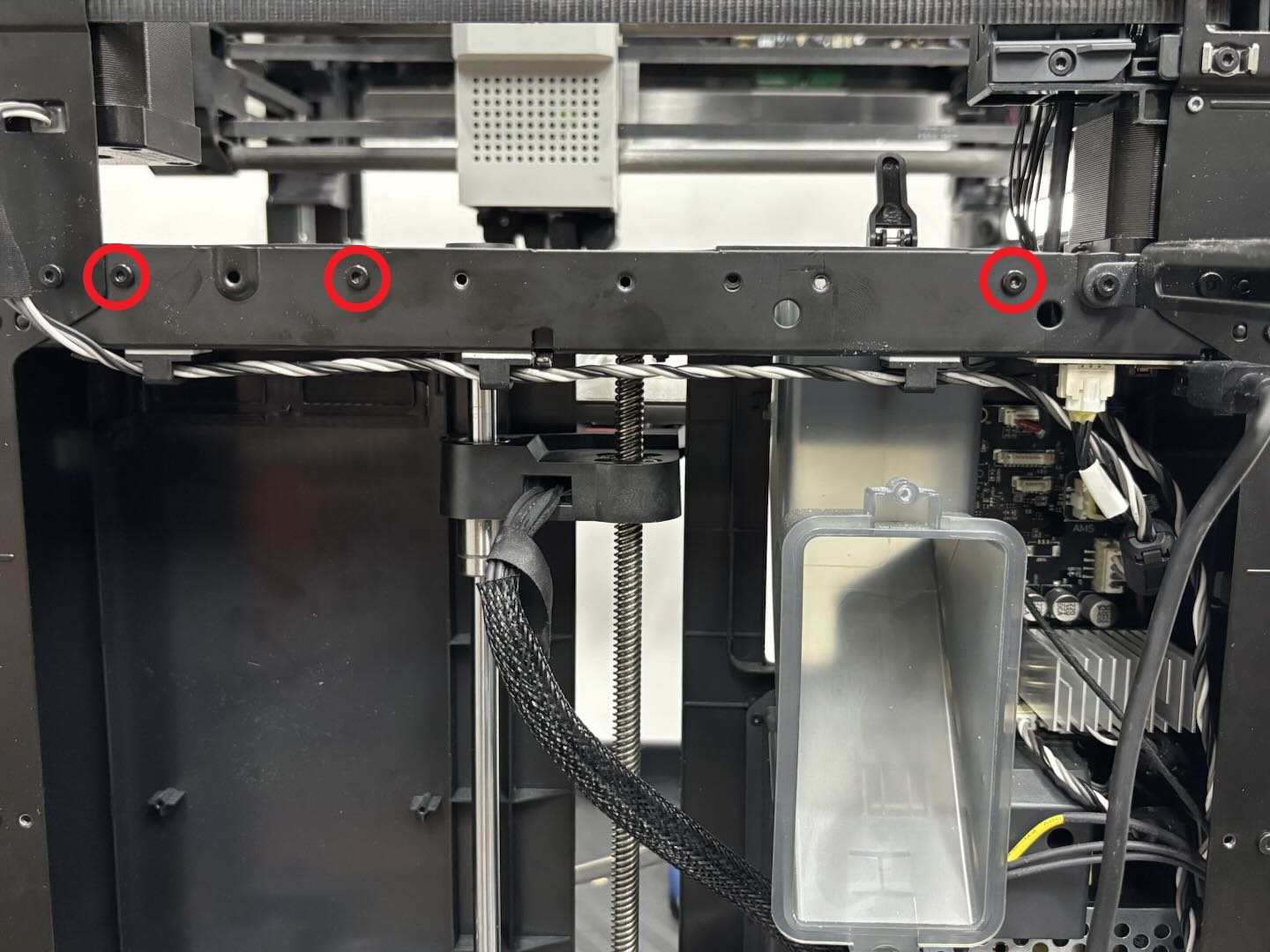
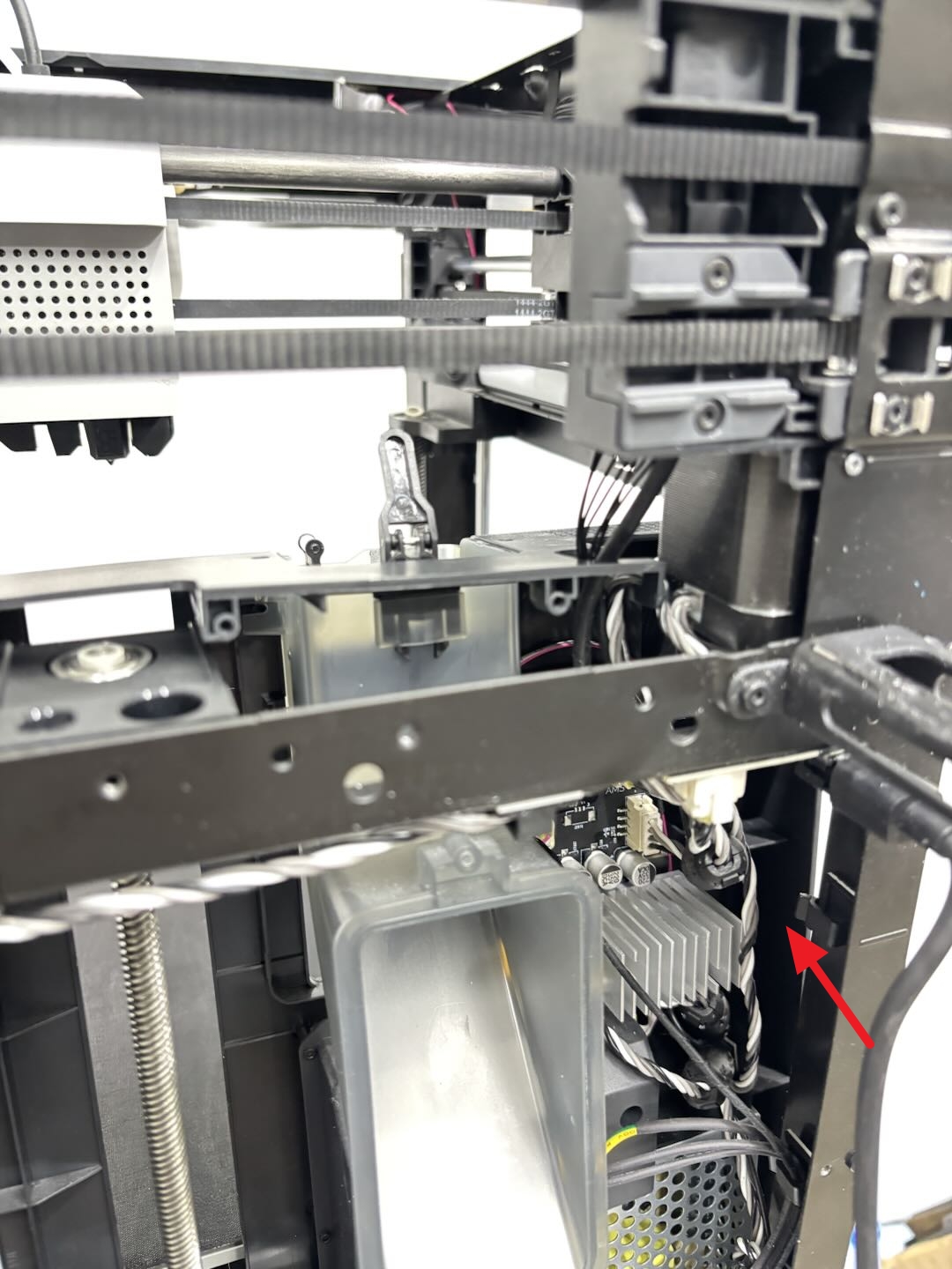
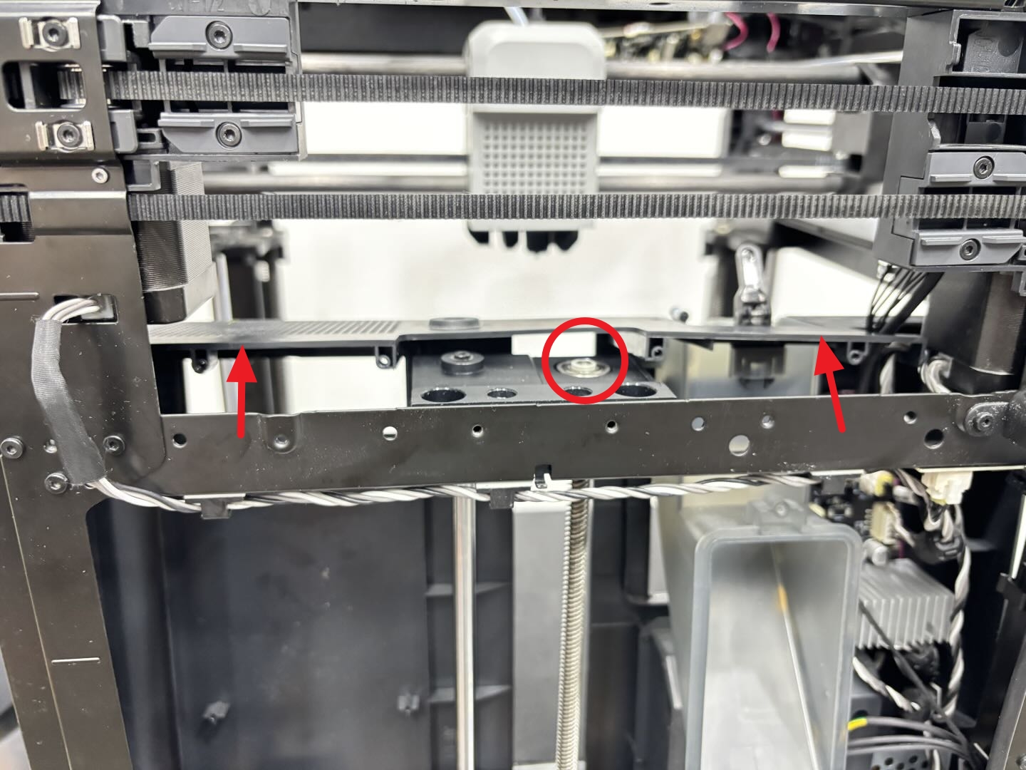
Use an H2.0 Allen key to remove the 3 liner fixing screws, then remove the motor cable from the clip and push the liner outward to expose the bearing on the top;
Please lower the heated to the bottom of the printer and push the liner outwards.
 |
 |
 |
¶ Step 5: Remove the lead screw/bearing
Lay the printer on its side, and then use an H2.0 Allen key to push against the bottom of the lead screw, and then forcefully knock the lead screw out.

Then remove the top bearing and silicone sleeve from the lead screw. If the bottom bearing remains on the printer base, knock it out with an Allen key; if it is removed together with the lead screw, remove the bearing from the lead screw.
Note: If the bearing is damaged, you can use the bearing included in the assembly.
¶ Install the lead screw from the back of the printer
¶ Step 1: Install the bottom bearing
Install the bearing at the bottom of the printer to the corresponding hole, and then tighten the 2 fixing screws with an H2.0 Allen key;

¶ Step 2: Install the lead screw and timing pulley
Install the plastic washer to the bottom of the lead screw, and then insert the lead screw into the Z-axis slider first, and then insert the lead screw into the bearing.
 |
 |
It is recommended to hold the lead screw with your hands to prevent it from falling;
Then align the surface on the Z belt timing pulley with the surface of the lead screw, insert the timing pulley into the screw, and tighten the 2 fixing screws with an H2.0 Allen key;
 |
 |
¶ Step 3: Install the top bearing and liner
Press the top bearing in from top to bottom, and then install the silicone sleeve;
Then buckle the liner back into place, tighten the 3 fixing screws with an H2.0 Allen key, and buckle the motor cable into the clip.
 |
 |
¶ Step 4: Fix the heatbed
Place the printer upright, first check if there is any foreign matter at the bottom of the printer, then lower the heatbed to the bottom of the printer (the heatbed will be automatically lowered to the bottom after the printer is turned over), and tighten the 3 fixing screws (BT3 x 28 x 15) using H2.0 Allen key.

You can use the screws that secured the heated bed during unboxing. If lost, you can use screws of the same specification (BT3x28x15, thread length 15mm), or purchase screws of this specification from the official Bambu Lab store.
¶ Step 5: Tighten the lead screw nut fixing screws
Use an H2.0 Allen key to tighten the 4 screws.
 |
 |
If the screw hole of the lead screw nut is not completely aligned with the hole on the Z-axis slider, please check whether the heatbed fixing screws in step 3 are fully screwed in place and whether there are foreign objects at the bottom of the heatbed. If screws are already tightened, you can try to manually turn the bottom timing pulley to align the screw holes.
¶ Step 6 Install the Z belt
Lay the printer on its side, rewind the Z belt around the Z-axis timing pulley and the Z motor, and then buckle the torsion spring back;

Then use an H2.0 Allen key to remove the 3 heatbed fixing screws, unlock the heatbed, manually pull the Z belt back and forth several times, and then tighten the Z tensioner screw with an H2.0 Allen key.
 |
 |
 |
¶ Step 7: Install the Z-axis lead screw silicone sock
-
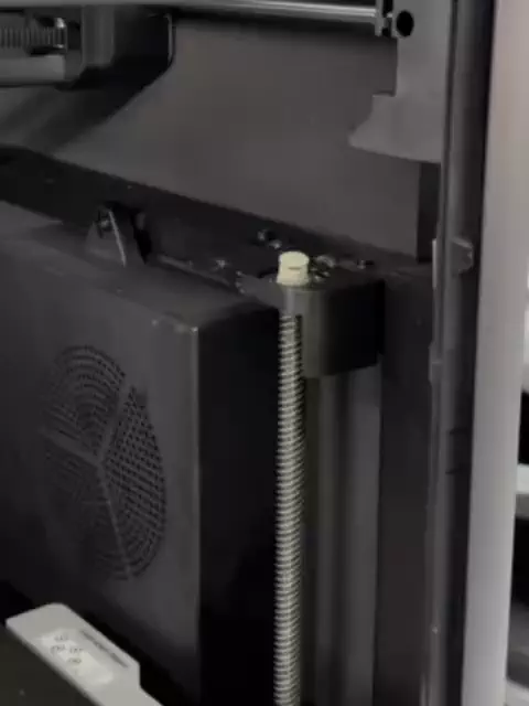
Place the silicone sock on the Z-axis lead screw. Control the up and down movement of the heatbed through the printer screen.
-
Press the silicone sock into the lead screw while the screw is rotating to make it fit the screw.
¶ Step 8: Install the printer rear panel
You can refer to the corresponding Wiki to install the rear panel according to the printer series:
¶ Verify the functionality
Connect the power supply and turn on the printer, click “Homing” to check if the printer can home correctly.
If homing does not work properly or the heated is not level, please follow the operation steps to check whether there is any problem with the assembly. After troubleshooting, run the device self-test again. If problems persist, contact the service team for further assistance.
¶ End Notes
We hope the detailed guide provided has been helpful and informative.
If this guide does not solve your problem, please submit a technical ticket, we will answer your questions and provide assistance.
If you have any suggestions or feedback on this Wiki, please leave a message in the comment area. Thank you for your support and attention!