¶ What is the AP board?
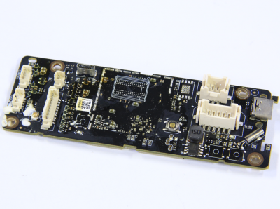
AP Board refers to the Application board, it is a circuit board that controls the interaction of information within the unit. It provides a self-contained operating environment that delivers all system capabilities needed to support the printer's applications, including memory management, system firmware, graphics processing and multimedia decoding.
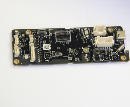
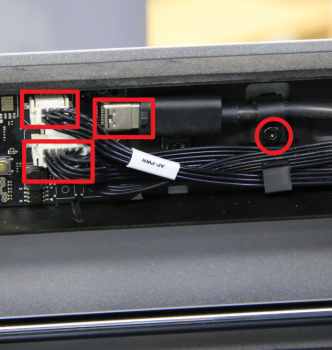
Connectors on the AP board:
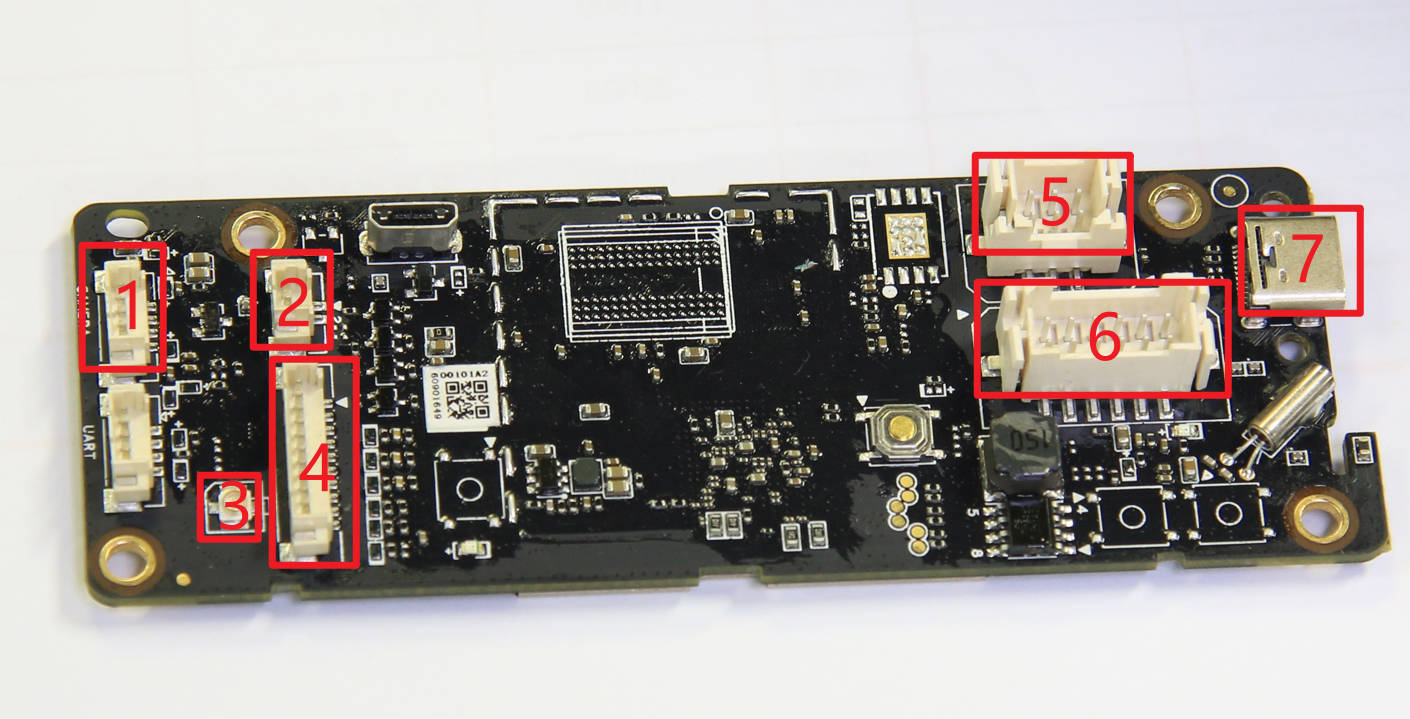
| NO. | Connect object | NO. | Connect object | NO. | Connect object |
| 1 | The chamber camera | 4 | Button PCBA | 7 | USB-C cable to Toolhead |
| 2 | The chamber LED | 5 | MC board (Power) | ||
| 3 | WIFI antenna | 6 | MC board (Communication) |
¶ When to use this guide
The AP board might need replacement in cases of abnormal voltages, components abnormally hot, burnt out, unrecoverable system failure, or firmware upgrade failure. Some of these can be detected through the log file which is sent to customer support.
¶ Tools and materials needed
- New AP board
- H2.0 Allen key
- Hair dryer
- Fixing tape or UV glue, UV lamp (to further stabilize the plug connector, not mandatory)
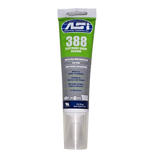
- Silicone glue
Only for reference
¶ Safety warning and Machine state before starting operation
Prior to commencing with the process in this guide, please make sure the machine is switched off.
¶ Operation guide
¶ Step 1 - (Disassembly) Power off
Power off the printer, unplug the power cord, and remove the top glass cover plate.
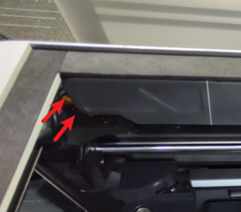
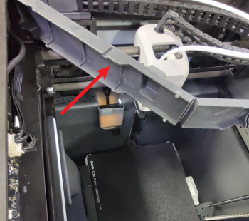
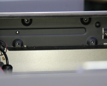
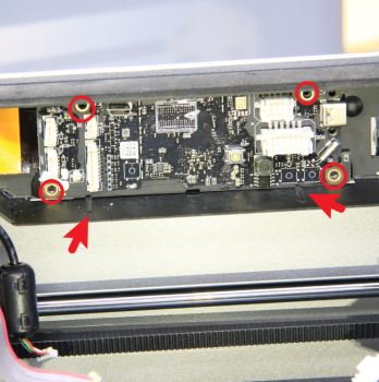
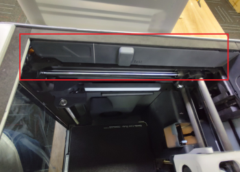
¶ Step 2 - Opening the AP board cover
Open the AP board cover as shown in the pictures below which is located at the upper left part of the machine.
 |
 |
|---|
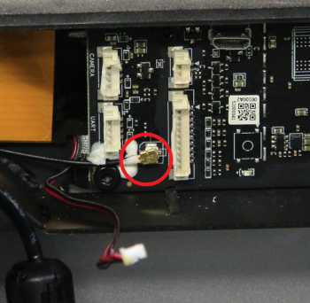
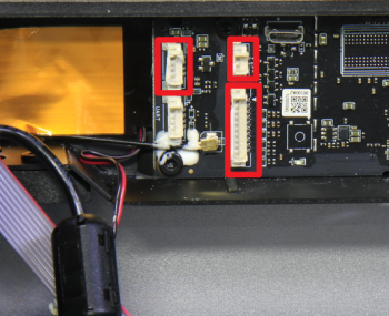
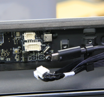
¶ Step 3 - Disconnecting the USB-C cable
Undo the single screw located on the cable retainer, and disconnect the USB-C cable and the two other cables next to it which are all connected to the AP board.
 |
 |
|---|
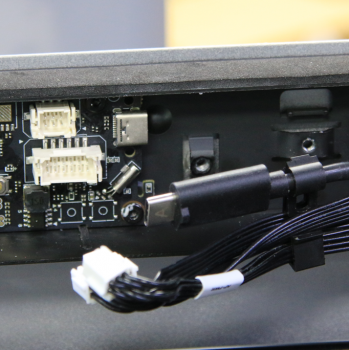
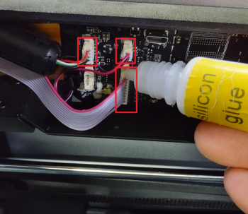
¶ Step 4 - Disconnecting the rest of the cables
Use the hair dryer to soften up the silicone glue securing the connectors, then disconnect the camera cable, the chamber LED cable, and the button board cable. Finally remove the WIFI antenna cable.
 |
 |
|---|
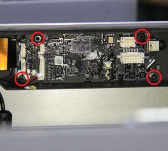
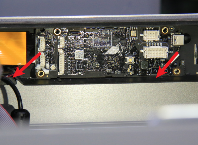
¶ Step 5 - Releasing the AP board
Undo the 4 screws holding the AP board in place and release the board carefully as there is still a ribbon cable attached to the end of it.
 |
 |
|---|
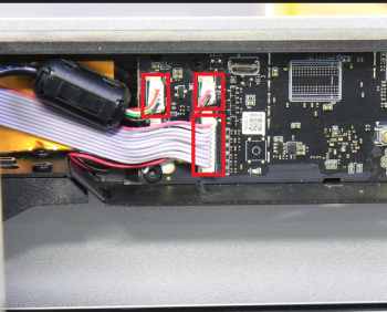
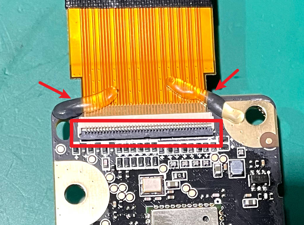
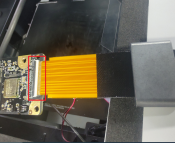
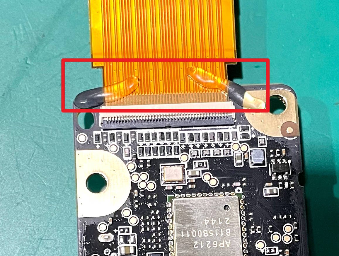
¶ Step 6 - Disconnecting the (FPC) ribbon cable
Heat up the UV glue holding the ribbon cable in place with a hair dryer. Unlock the connector holding the ribbon cable secured by very gently lifting up the little black flat marked in the below image with a red square. Once done, clean up the UV glue if any of it remains on the pins of the FPC ribbon cable.
 |
 |
|---|
¶ Step 7 - (Assembly) Connecting the FPC ribbon cable
Prepare the replacement AP board, and slide the FPC ribbon cable in the connector on AP board. Secure the ribbon cable by pressing on the little black plastic flap on the connector.
 |
 |
|---|
¶ Step 8 - Applying glue to FPC ribbon cable connector
Apply some UV glue on the connector and expose the glue to UV light to harden. Alternatively, apply silicone glue instead, however, let the silicone glue stand for 60 minutes after applying before proceeding.
¶ Step 9 - Installing the AP board
Once the glue has solidified, align the holes of the AP board to the frame and secure it in place using 4 screws.
 |
 |
|---|
¶ Step 10 - Connecting the cables
Start by connecting the cables to the left of the AP board (same side as the ribbon cable), apply some silicone glue to the WIFI cable, the LED cable, the camera cable, and the button board cable, let them stand for at lease 30 mintues.
 |
 |
|---|
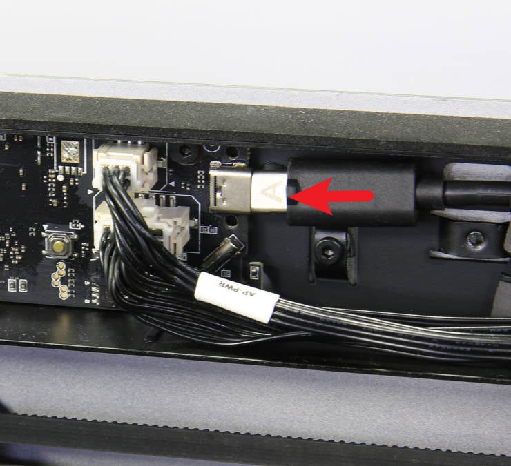
¶ Step 11 - Connecting the rest of the cables
Connect the 2 standard cables first, followed by the USB-C cable to the AP board, and then secure the cable retainer with a screw.
Pay attention that the letter A should face outward.
 |
|
|---|
¶ Step 12 - Closing the AP cover
Press fit the AP cover back in place securely and finally place the glass top cover back on.
¶ Step 13 - Activate the new SN
After the AP board is replaced, its SN is not activated. Therefore the printer cannot be bound to your account. The step of binding the machine should be skipped when it is turned on for the first time. You can do it once the SN is activated.
After confirming that the replacement is completed, the printer SN needs to be replaced.
So please contact the service team and provide both the new SN and the old SN to complete the SN replacement. (Begins with 00M or 00W) Please refer to this wiki: Activate New Serial Number-How to find SN.
¶ Verify the Functionality
¶ Check the indicator lights on the control board
Normal State: the AP board has 2 indicator lights, one is constantly red, and the other flashes red once per second
Before tightening all screws, you may temporarily install or leave the cover off (be cautious of electrical safety and operate with the power disconnected). Then power on to check whether the indicator lights are functioning normally. If the lights are normal, fasten the screws to avoid rework.
https://public-cdn.bblmw.com/wiki/video/X1-AP.mp4
Printer Circuit Failure Troubleshooting - X1 Series
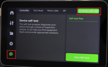
¶ Connect the power cable and turn on the power. Initiate a print and check if there is an error.
Connect the power cord and turn on the power. Run a Device self-test operation as shown below and if no errors occur, the replacement was successful.
¶ End Notes
We hope the detailed guide provided has been helpful and informative.
If this guide does not solve your problem, please submit a technical ticket, we will answer your questions and provide assistance.
If you have any suggestions or feedback on this Wiki, please leave a message in the comment area. Thank you for your support and attention!