If the TH board you received is different from the description in this article, it may be because the TH version you received is V9, while the TH board described in this article is V8.
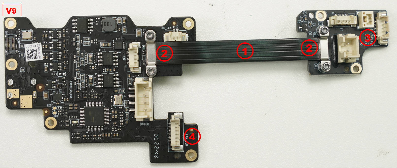
The V9 board replaces the older V8 board.
For installation instructions on V9, please refer to this wiki article. Replace the toolhead_boards_(V9)
¶ What is the toolhead TH board assembly
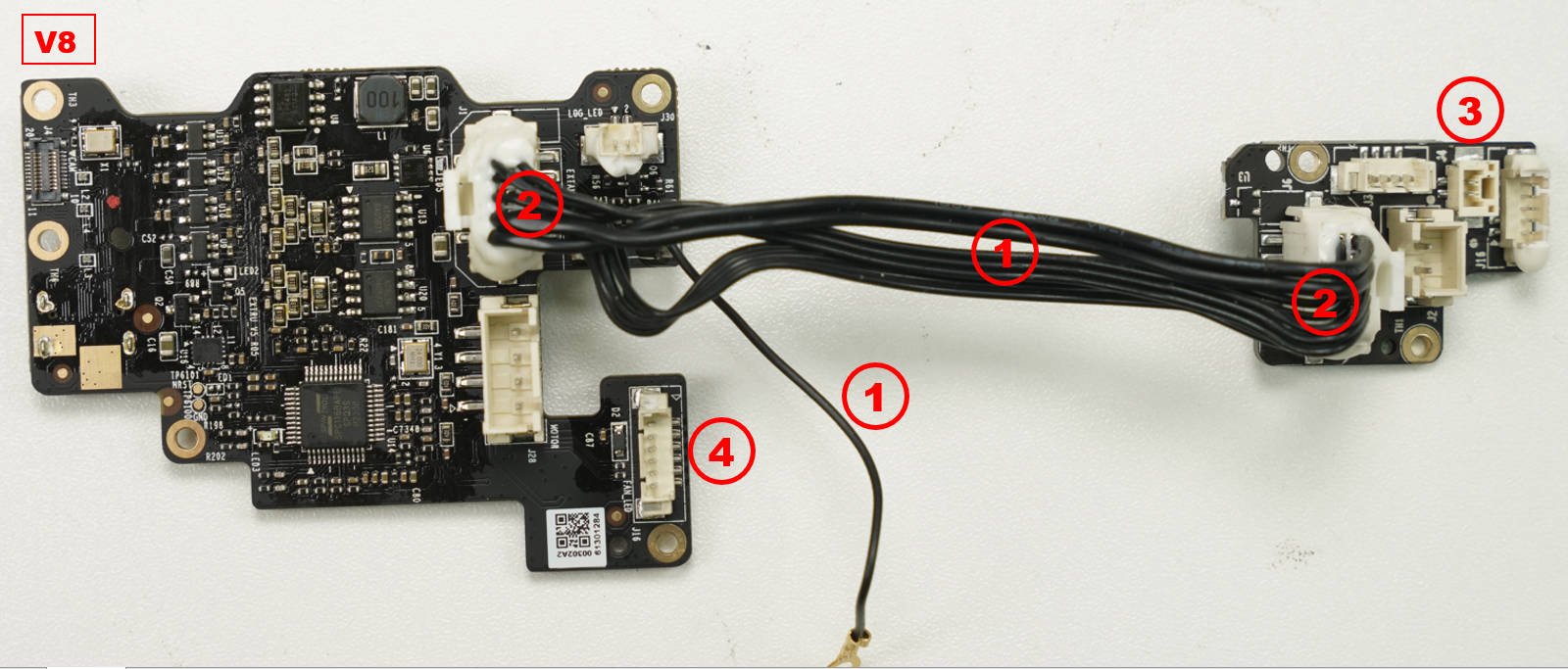
The toolhead board assembly is an assembly that includes 2 PCB boards (the extruder board and the interface board) and connecting cables.
The cables are fixed to the connectors with silicon glue.
V8 (older version) - This board was replaced by the newer V9.
V9 (new version) - This is the current TH board present in the X1C. If you have this board version, please follow this guide
¶ When to use
- Connectors and components damaged
- Issues were found through a printer LOG analysis.
¶ Tools and materials needed
- H1.5 + H2 Allen Key
- Bambu Lab TH board assembly
- Silicon glue

¶ Safety warning and Machine state before starting operation
Power OFF the printer before doing any maintenance work.
¶ Operation video
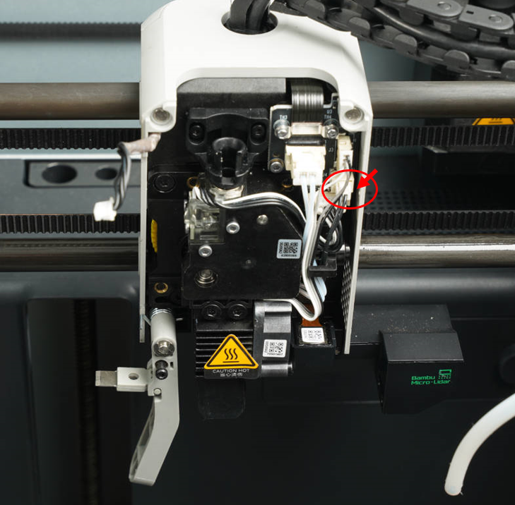
Note: Use a hair dryer to heat the silicone glue that applies to the connectors before disconnecting it to prevent damage to the connectors.
The thermistor plug has a buckle/latch (different than the fan and heater) that they need to push to unlatch rather than pull on the wires/plug till the whole PCB connector comes off.
¶ How to verify completion/success
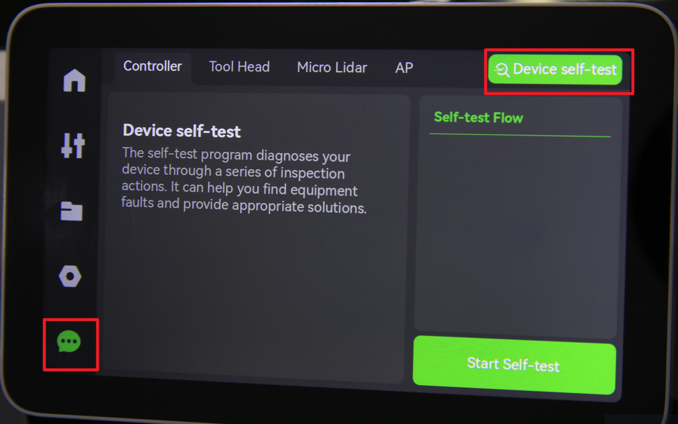
- Power ON the printer
- Run a Device self-test operation as shown below and if no errors occur, the replacement was successful.
Should you come across any issues, first retrace your steps and check all connections to try again. If problems persist, contact the service team for further assistance.