¶ What is the TH Board Set V9?
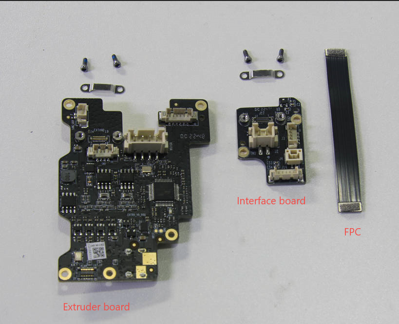
The new version TH Board Set V9 of the X1 and X1C (not for X1E) includes the extruder board, Extruder Interface Board V9 - X1 Series, and TH Board FPC Cable V9 - X1 Series. They can be replaced according to the damaged parts.
¶ When to use?
- The connectors and components were damaged
- Issues were found through a printer LOG analysis
¶ Tools and materials needed
- H1.5 hex key
- Bambu Lab tool head board(s)
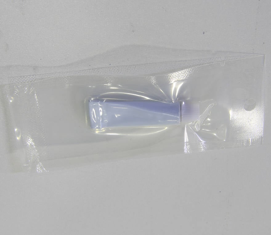
- Silicon glue
¶ Safety Warning
IMPORTANT!
It's crucial to power off the printer before performing any maintenance work on the printer and its electronics, including tool head wires, because leaving the printer on while conducting such tasks can cause a short circuit, which can lead to additional electronic damage and safety hazards.
When you perform maintenane or troubleshooting on the printer, you may be required to disassemble some parts, including the hotend. This process can expose wires and electrical components that could potentially short circuit if they come into contact with each other or with other metal or electronic components while the printer is still on. This can damage the electronics of the printer and cause further damage.
Therefore, it's essential to switch off the printer and disconnect it from the power source before doing any maintenance work. This will prevent any short circuits or damage to the printer's electronics. By doing so, you can avoid potential damage to the printer's electronic components and ensure that the maintenance work is performed safely and effectively.
If you have any concerns or questions about following this guide, open a new ticket in our Support Page and we will do our best to respond promptly and provide you with the assistance you need.
¶ Differences between the versions
The main differences between the new and old versions of the t TH Board Set V9. As shown in the pictures below, V8 is the old version, and V9 is the new one.
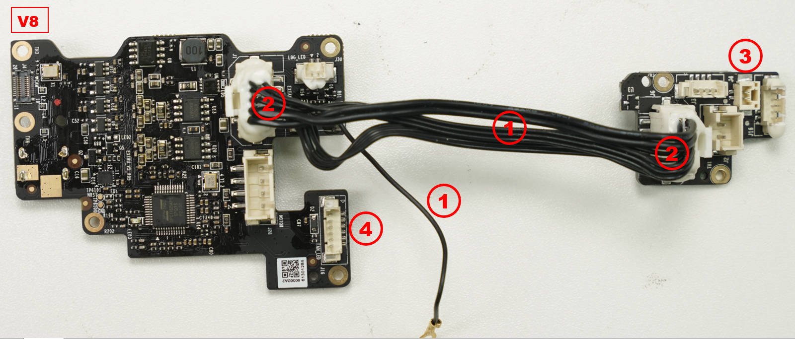
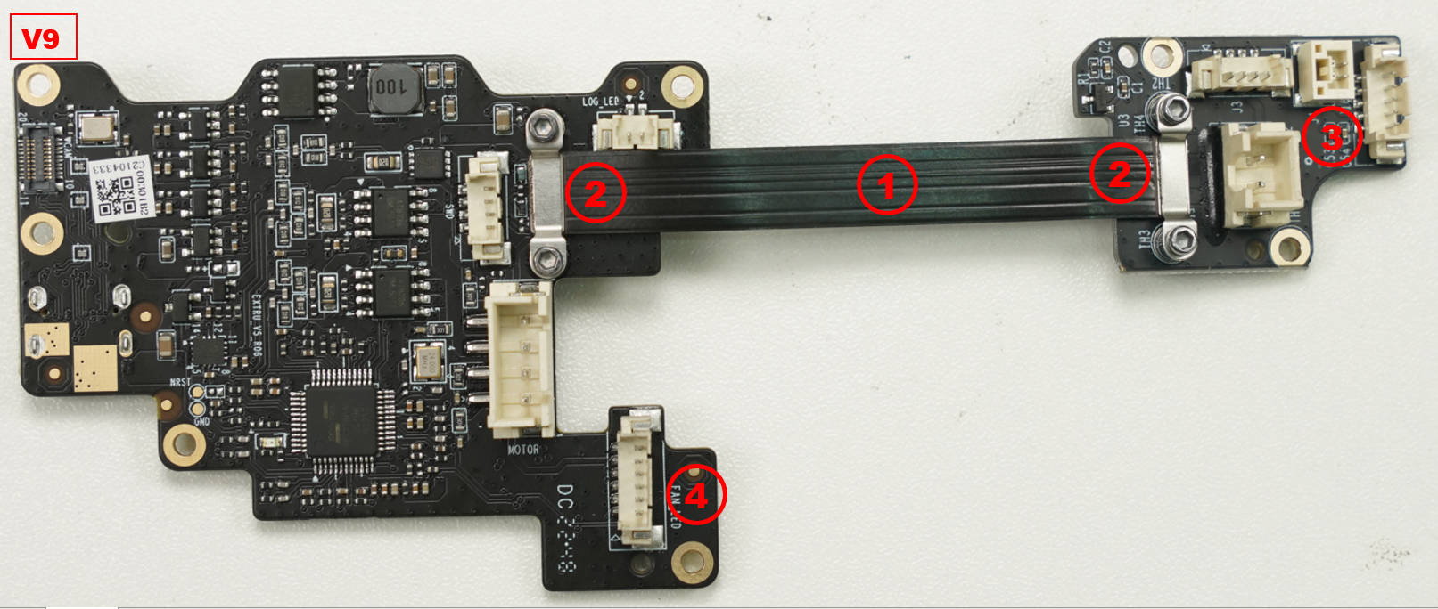
1. Combine the cable and ground wire into one FPC Cable;
2. The reinforcement method at both ends of the connecting cable is changed from silicone fixation to bracket reinforcement;
3. The direction of the NTC connector on the interface board is changed;
4: The direction of the connector used to connect the extruder main board and the front housing is changed.
¶ Operation Guide
Note: Before disconnecting the connectors, it is recommended to use a hair dryer to gently heat the silicone glue applied to them. This helps prevent damage to the connectors. Alternatively, you can use tweezers to remove some of the glue before disconnecting. After reconnecting, it is also advisable to apply silicone glue for reinforcement.
When installing the FPC Cable, it is vital to carefully consider the installation direction. Improper direction can result in misalignment of the FPC Cable's BTB connectors. It is important not to force the installation, as this can cause damage to the BTB connectors.
¶ Video guide
¶ Operation tips and tricks:
If you encounter difficulties while installing the FPC Cable and small screws on the tool head, you can try the following workaround: Place the three parts on a table and install them in that position. After they are properly connected, slide the FPC cable into the Tool Head from right to left.
1. Place the 2 Tool Head boards on the table or workbench in front of you.
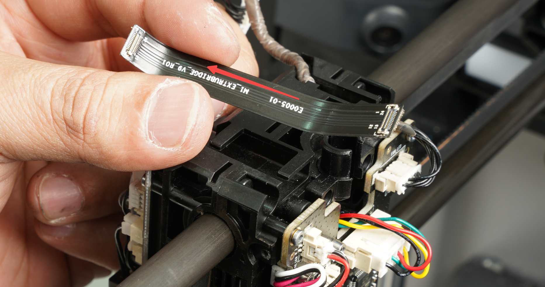
2. Ensure that the FPC Cable is oriented correctly, referring to the provided pictures:
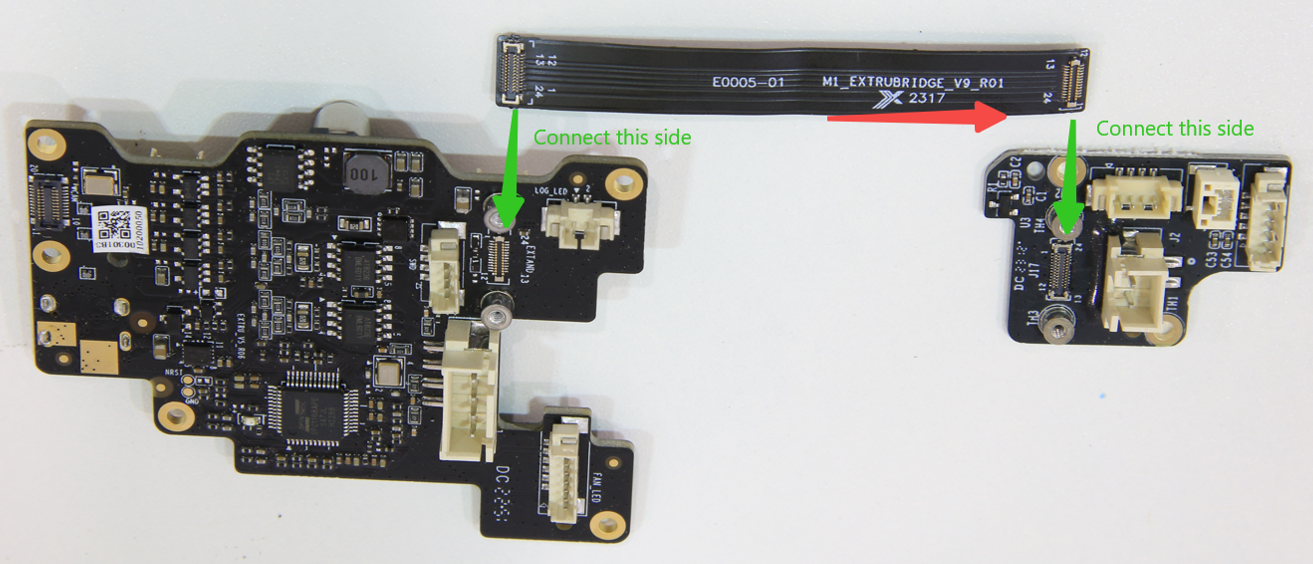
The FPC cable features a row of text, and the direction of reading along the text should be towards the small board (the Extruder Interface Board) following the arrow direction.
3. Assemble the cable while keeping the boards on the table. Make sure not to overtighten the screws and ensure that the metallic shields are in place to secure the connector, as shown in the following image:
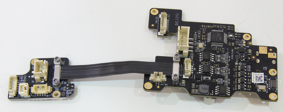
4. When you're ready, hold the boards in the specified orientation.
5. Next, slide the FPC cable into position on top of the Tool Head, moving from right to left.
6. Once you have completed these steps, you can proceed with steps 8, 9, 10, and 12, and subsequent instructions provided in the wiki.
¶ Step 1 - Remove the front housing assembly
Open the front housing assembly by carefully separating the components. Disconnect the connecting cable and proceed to remove the front housing assembly.
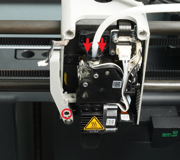
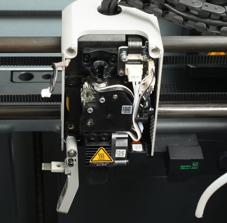
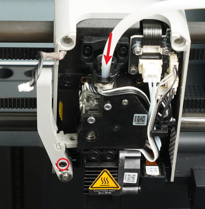
¶ Step 2 - Loosen the cutter lever
Use the H1.5 Allen wrench to loosen the screw of the cutter lever, allowing it to sag naturally. Press down to disconnect the PTFE tube from the extruder.
 |
 |
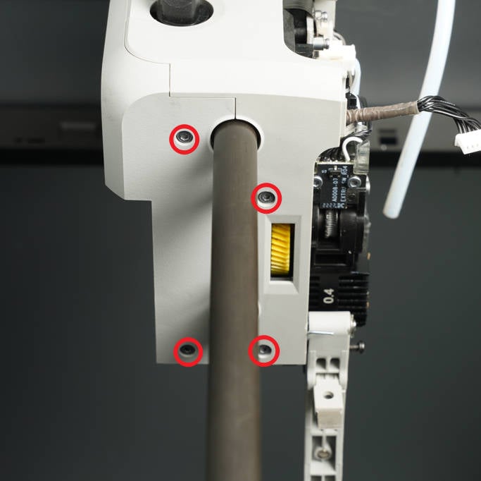
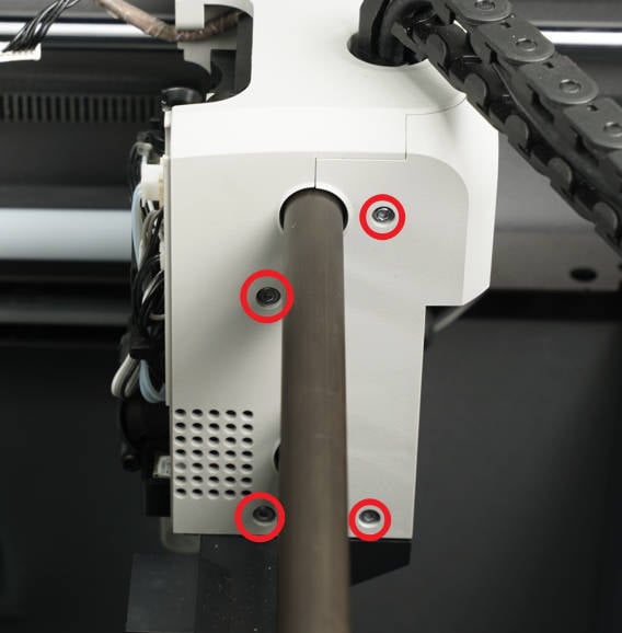
¶ Step 3 - Remove the tool head housing
Remove the 8 screws fixing the tool head housing with the H1.5 hex key on both sides, and remove the tool head rear cover and middle frame.
 |
 |
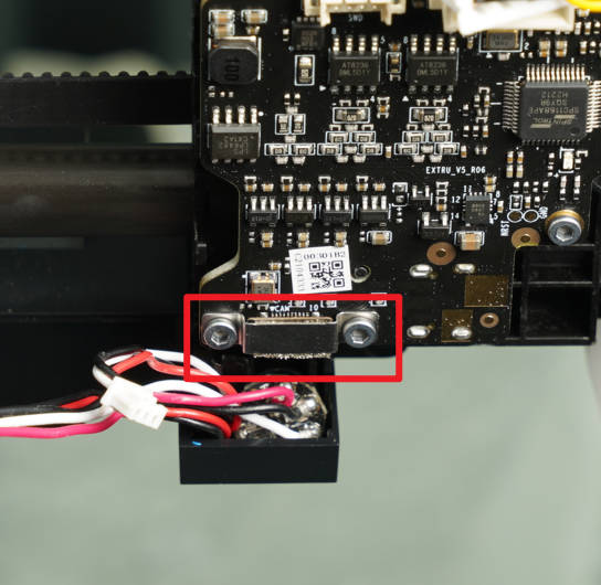
¶ Step 4 - Disconnect the USB cable
Disconnect the USB cable from the extruder main board, and then remove the main board along with the bracket from the tool head.
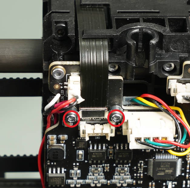
¶ Step 5 - Remove the connecting FPC
Unscrew the screws at both ends of the connecting FPC Cable using the H1.5 hex key, remove the brackets, disconnect the cable, and then remove it from the tool head.
Note: The 4 screws used in this step are smaller in size. Be cautious not to overtighten the screws to avoid breakage, and make sure not to mix them with other screws.
 |
 |
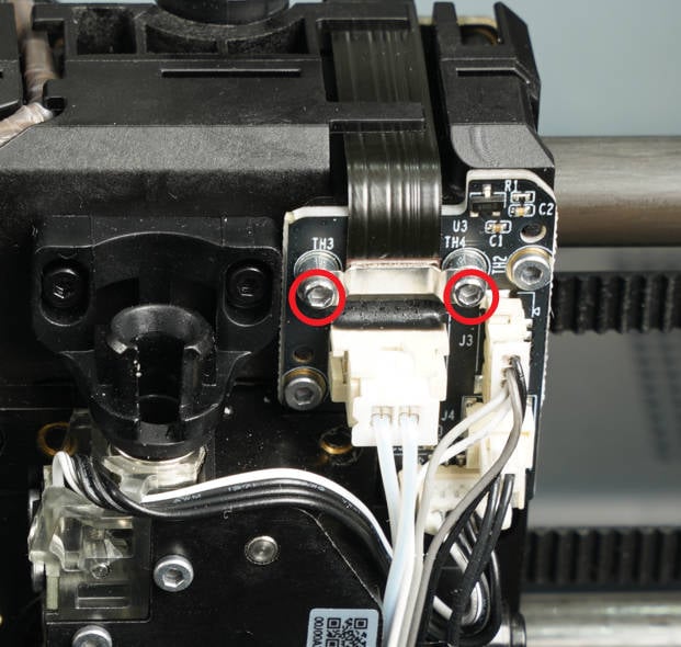
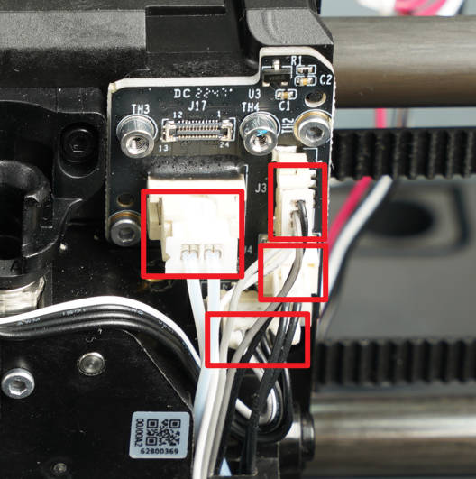
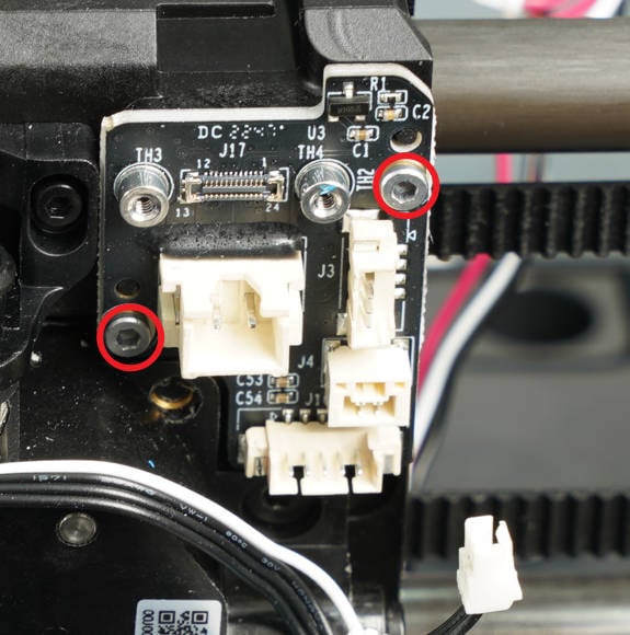
¶ Step 6 - Remove the interface board
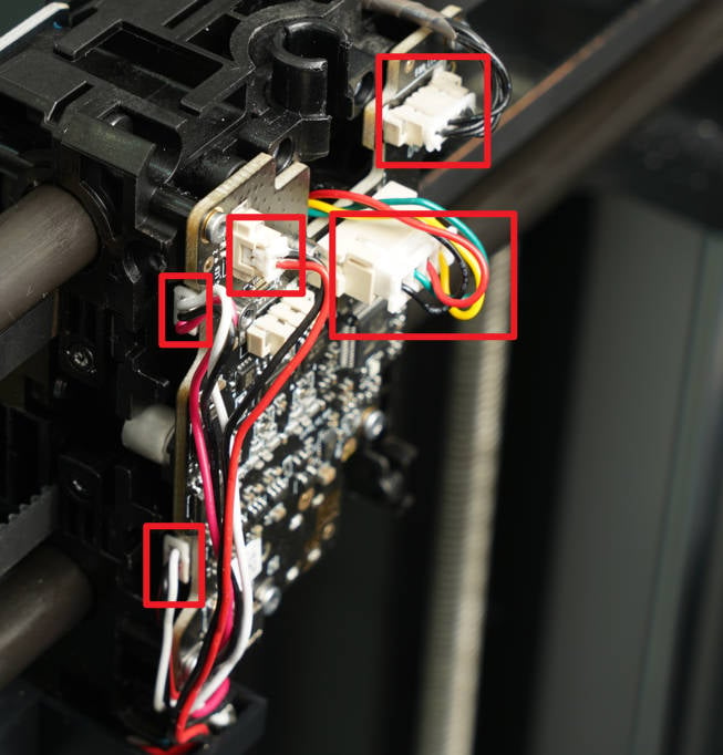
Disconnect the 4 cables that are connected to the interface board. Then, using an H1.5 hex key, remove the two screws securing the interface board. Finally, remove the interface board from its position.
 |
 |
Warnings: The thermistor plug is equipped with a buckle/latch (which differs from the fan and heater plugs). To disconnect it, you need to push the latch to unlatch it instead of pulling on the wires/plug, as this may cause the entire PCB connector to come off.
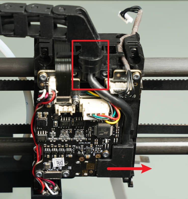
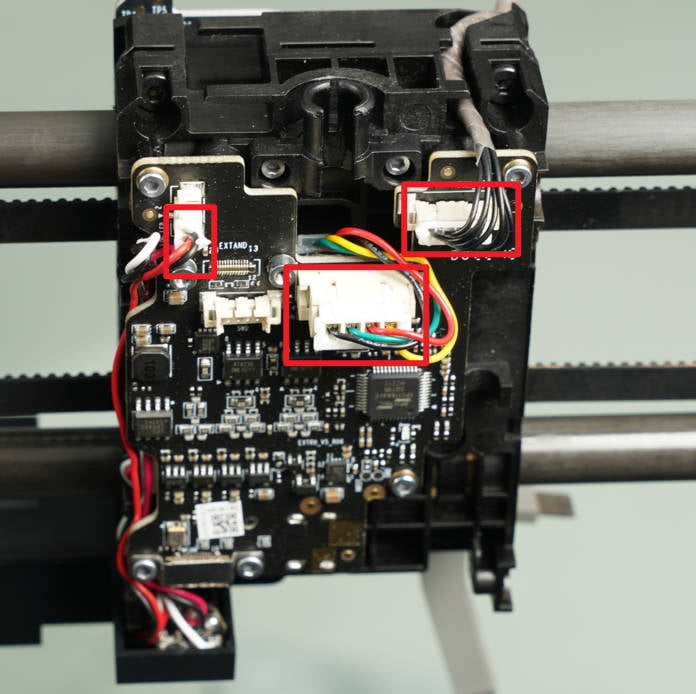
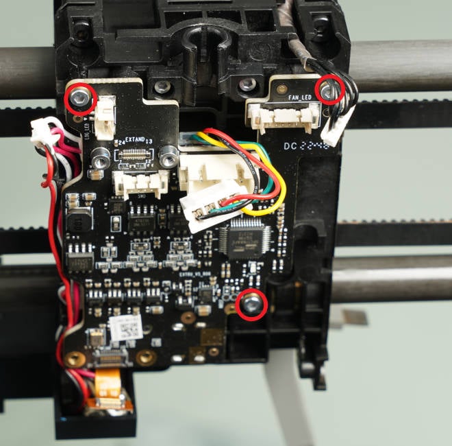
¶ Step 7 - Remove the extruder main board
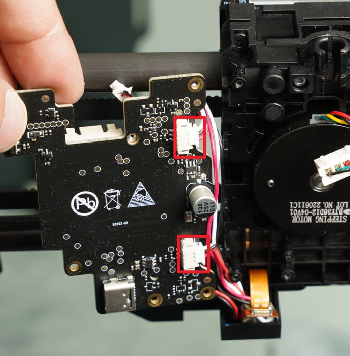
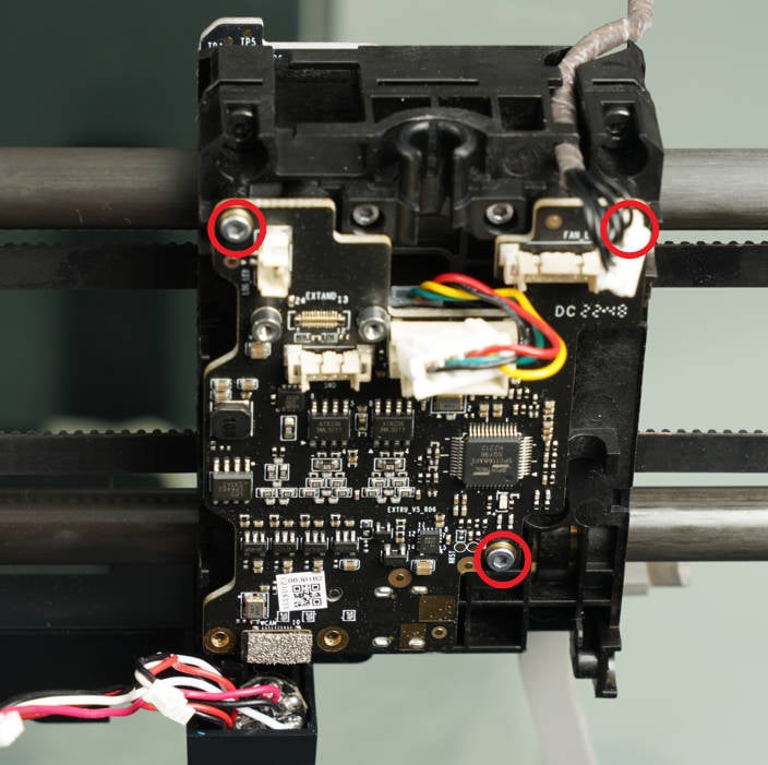
Disconnect the 3 cables that are connected to the extruder main board. Then, using an H1.5 hex key, remove the three screws securing the extruder main board. Turn the extruder main board to the left and disconnect the two laser cables. Finally, remove the extruder main board from its position.
 |
 |
 |
¶ Step 8 - Install the extruder main board
Install the extruder main board onto the tool head and secure it with three screws. Then, connect the camera flexible cable and install the bracket. Finally, use two screws to lock the bracket in place.
 |
 |
¶ Step 9 - Connect the cable (extruder main board)
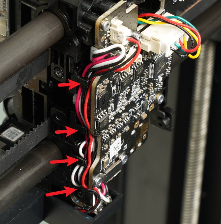
Connect the 5 cables to the extruder main board, ensuring to align the connectors correct. It is recommended to reinforce the connections with silicone, as done before when disconnecting them. Arrange the three lidar cables as shown in the diagram to prevent damage and interference during enclosure installation.
 |
 |
¶ Step 10 - Install the interface board
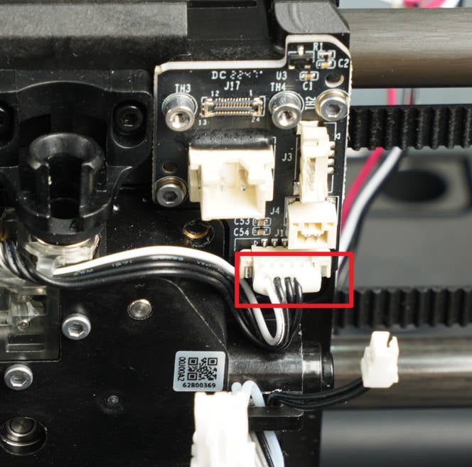
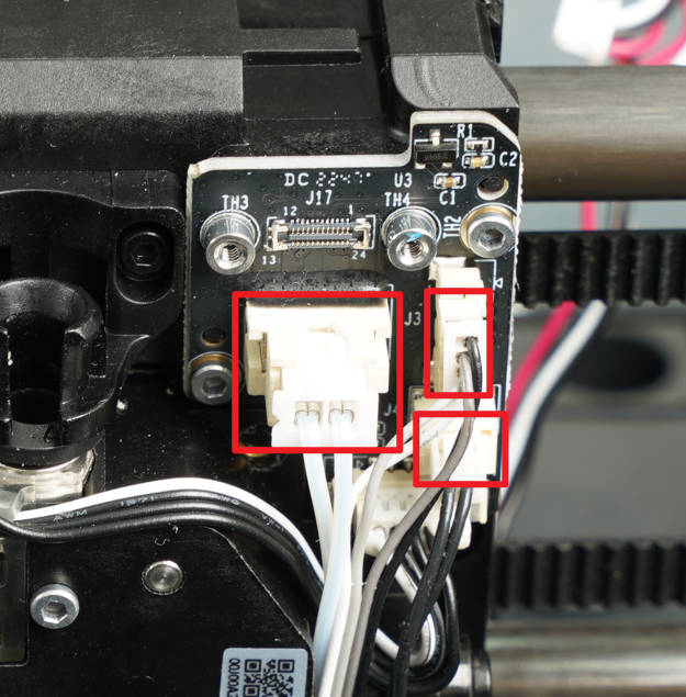
Install the interface board onto the tool head and secure it with two screws. Next, connect the cable of the Hall board (extruder). It is recommended to reinforce the connection with silicone glue. Afterward, connect the 3 hotend cables.
|
 |
 |
¶ Step 11 - Install the connecting FPC
The "male" BTB connector should be connected to the small board(the interface board).
The "female" BTB connector should be connected to the big board(extruder board).
We strongly recommend you carefully check the BTB connectors on the FPC and the board before installation. The female BTB connectors must correspond to the male BTB connectors.
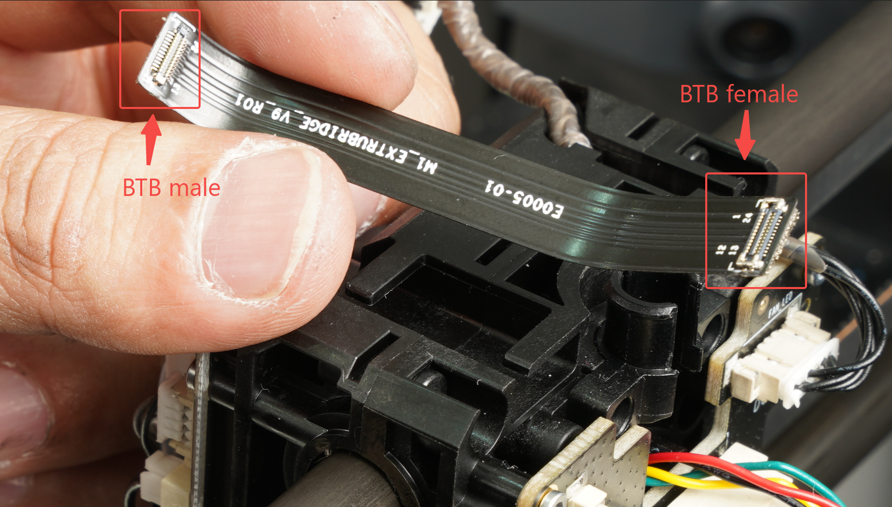
If you find it difficult to distinguish the direction using the BTB connectors, you can also determine it by observing the direction of the text on the FPC cable.
The FPC cable has a row of text, and the direction of reading along the text should be towards the small board(the interface board) along the arrow direction.
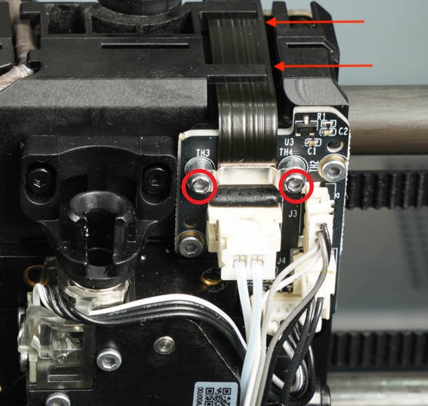
After confirming the direction of connecting the flat cable, install it into the slot above the tool head. Then connect them to the connectors of the interface board and the extruder main board, and reinforce them with crimping brackets and screws.
Note: The 4 screws used here are smaller in size. Avoid tightening the screws vigorously to prevent the screws from breaking and cannot be mixed with other screws.
|
|
¶ Step 12 - Connect the USB cable
Connect the USB cable to the extruder main board, press the USB cable into the cable base, and then mount the cable bracket in place.
¶ Step 13 Verify the TH board assembly, especially if the FPC is installed correctly.
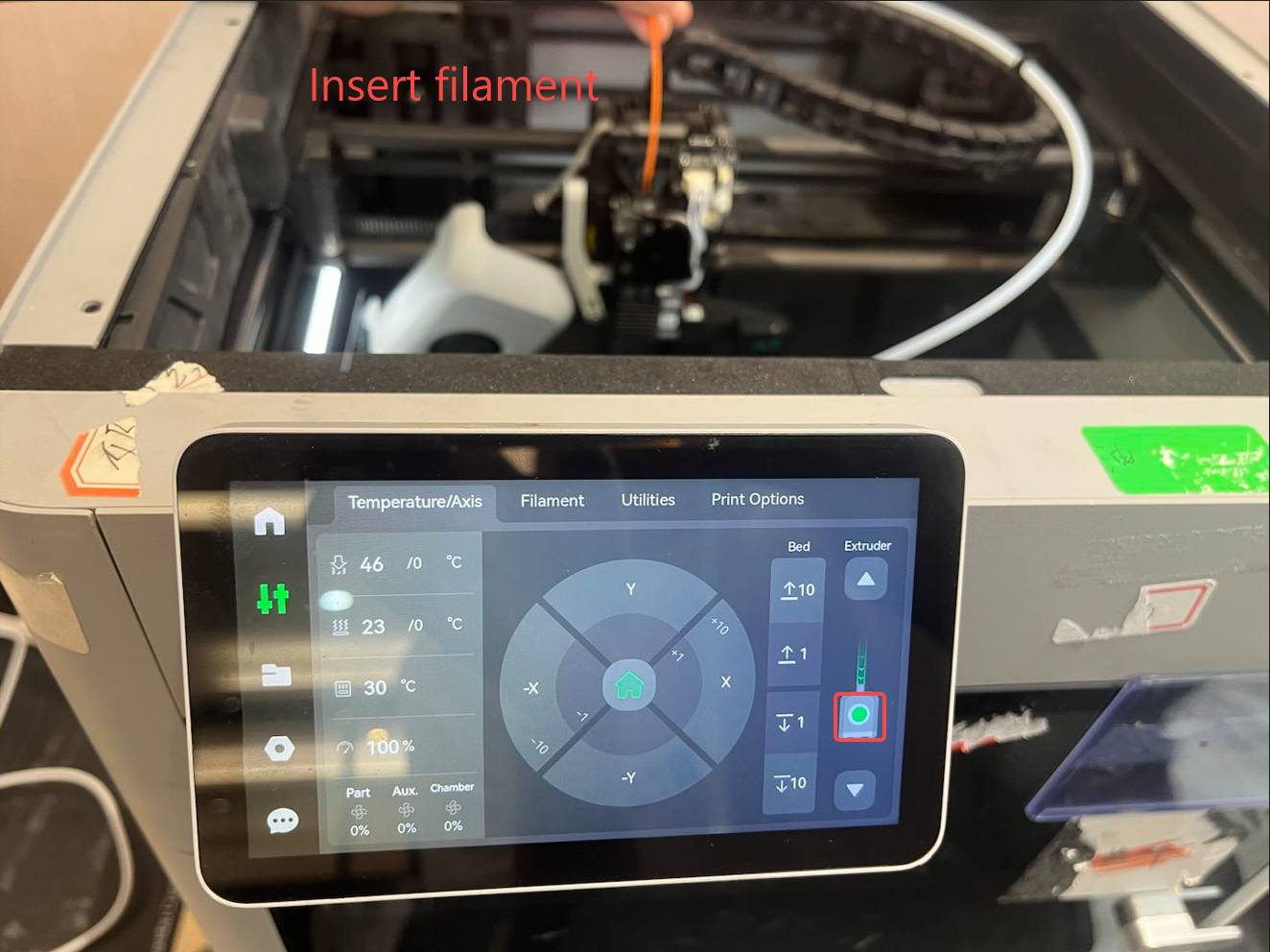
To check if the TH board assembly is installed correctly before installing the tool head housing, you can perform the following 2 tests:
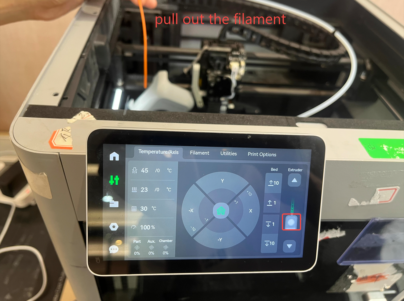
1. Use a short filament to test whether the Hall sensor of the extruder can detect the filament normally. For example, when the filament is inserted, there will be a green mark here, and the green mark will disappear when the filament is pulled out.
 |
 |
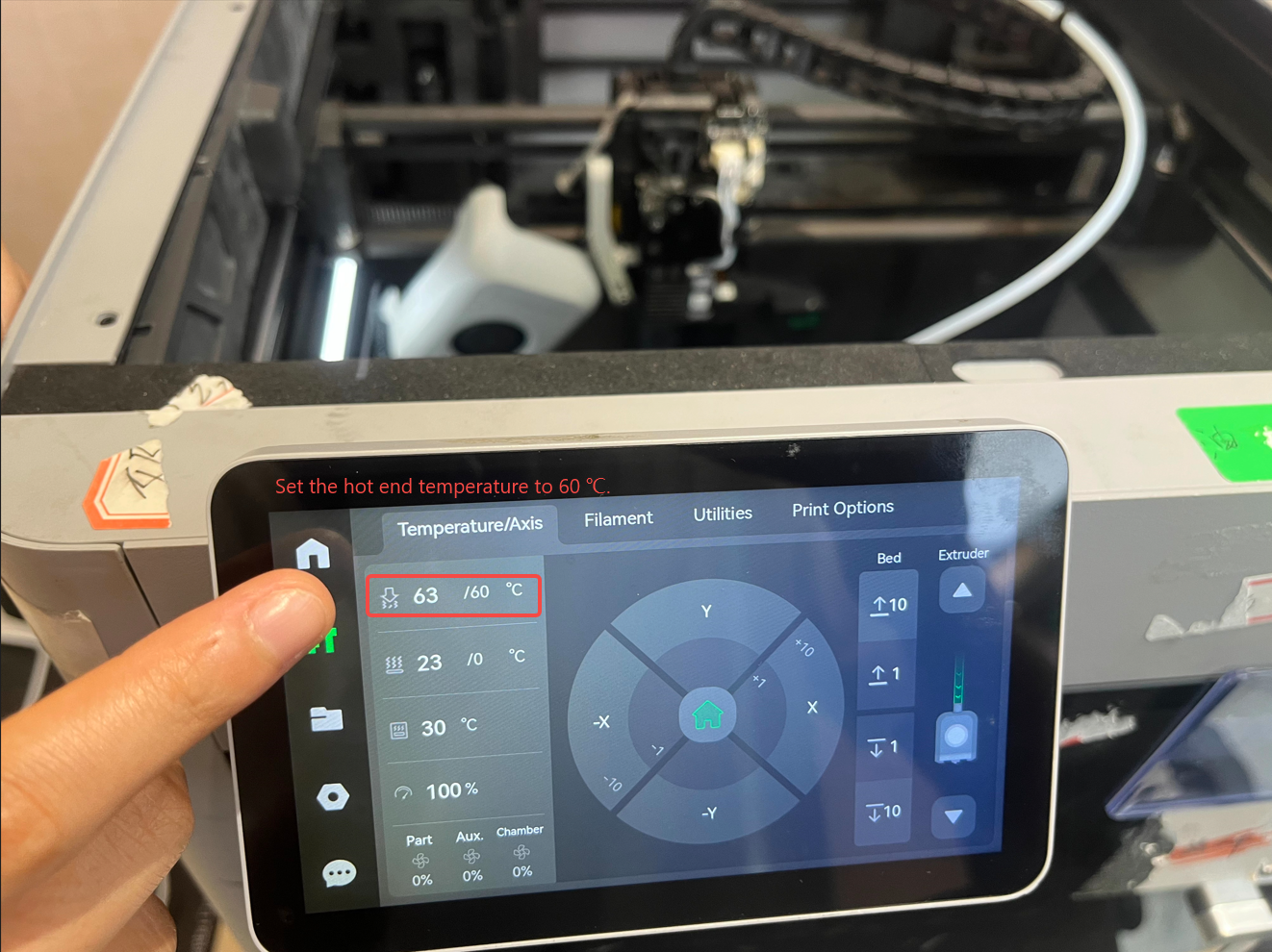
2. Set the hot end temperature to 60 ℃. When the temperature is higher than 50 ℃, the hotend fan will be turned on. Should the printer not be able to pass these two tests after installing the Tool Head board, it is likely that the flexible cable that is connecting both boards is not installed properly. Please reinstall it.
¶ Step 14 - Install the tool head housing
Install the middle frame and rear cover of the tool head, and lock four screws on both sides, respectively.
|
|
¶ Step 15 - Install the cutter lever
Lift the cutter lever by hand, slide the cutter into the extruder along the cutter slot, lock the fixing screw, and connect the PTFE tube.
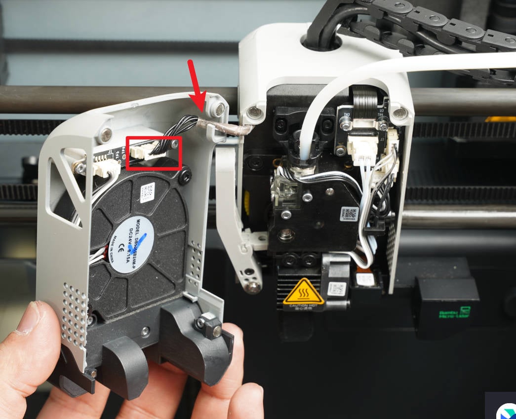
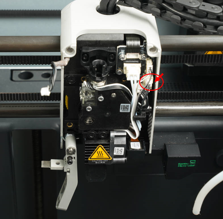
¶ Step 16 - Install the front housing
Connect the front cable as shown in the figure below and then close the front housing.
¶ Operation video(Pending)
Note: Use a hair dryer to heat the silicone glue that applies to the connectors before disconnecting it to prevent damage to the connectors, or use tweezers to remove some glue first.
¶ How to verify completion/success
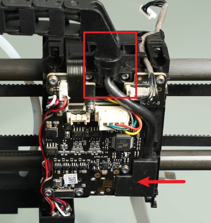
¶ Check the indicator lights on the control board
Normal State: the TH board indicator light is constantly red
Before tightening all screws, you may temporarily install or leave the cover off (be cautious of electrical safety and operate with the power disconnected). Then power on to check whether the indicator lights are functioning normally. If the lights are normal, fasten the screws to avoid rework.
https://public-cdn.bblmw.com/wiki/video/X1-TH.mp4
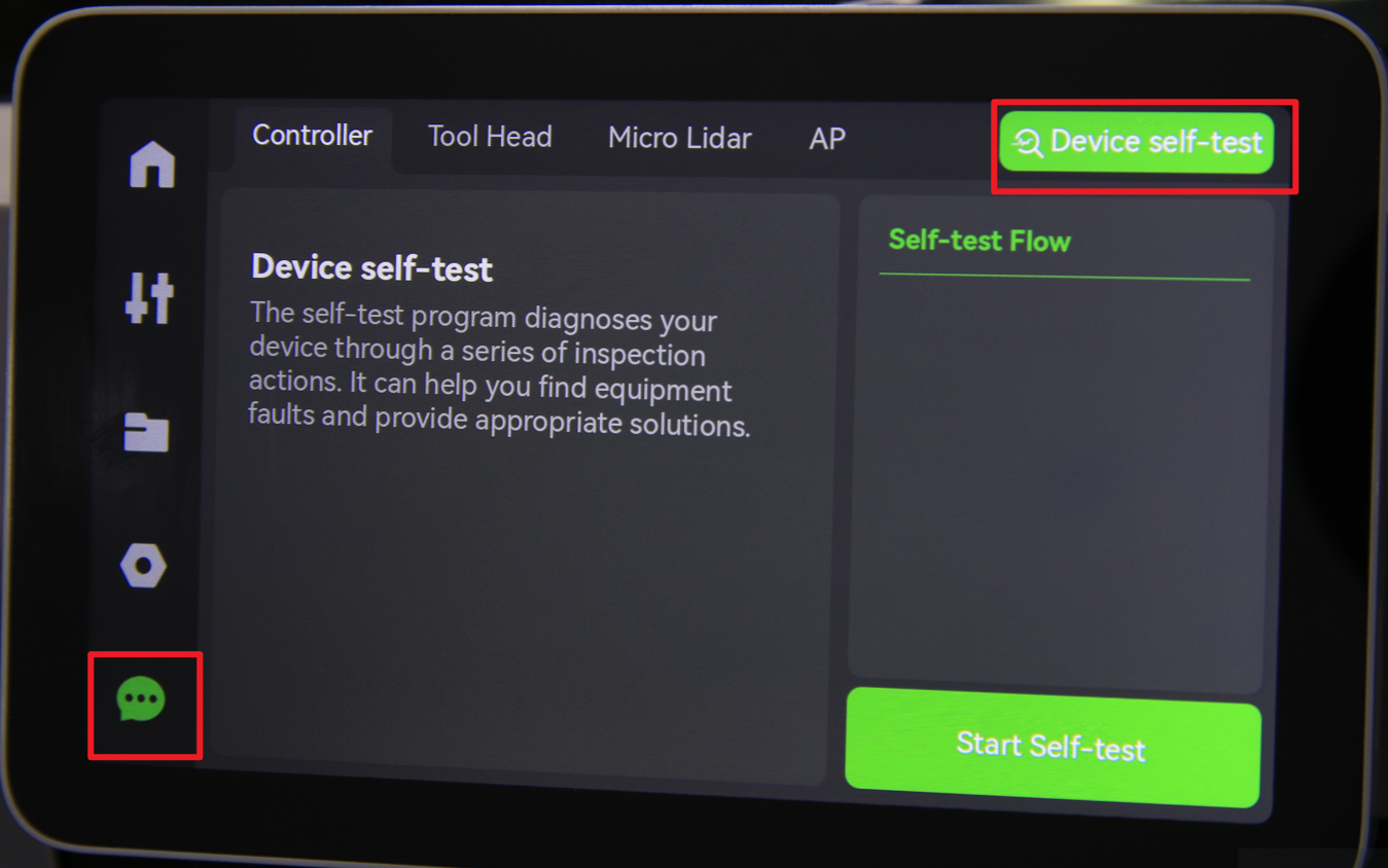
¶ Connect the power cable and turn on the power. Initiate a Device self-test operation and check if there is an error.
- Power ON the printer
- Run a Device self-test operation as shown below and if no errors occur, the replacement was successful.
¶ End Notes
We hope that the detailed guide we shared with you was helpful and informative.
We want to ensure that you can perform it safely and effectively. If you have any concerns or questions regarding the process described in this article, we encourage you to reach out to our friendly customer service team before starting the operation. Our team is always ready to help you and answer any questions you may have.
Click here to open a new ticket in our Support Page.
We will do our best to respond promptly and provide you with the assistance you need.