¶ X-axis carbon rods assembly
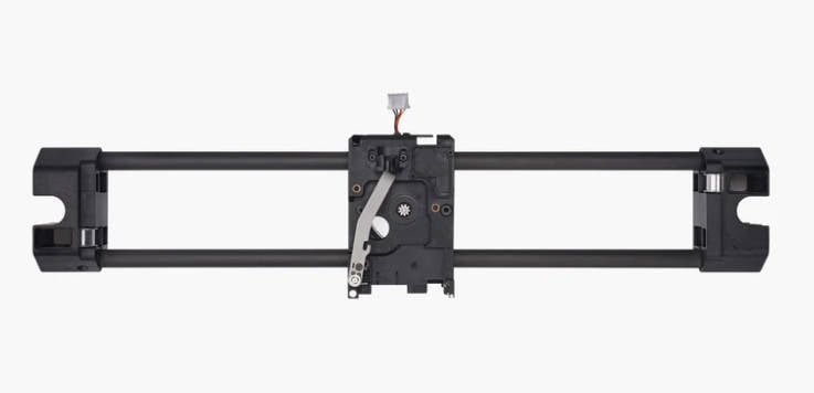
The X carbon rods assembly is mainly composed of two Y sliders, a tool head carriage (including extruder motor, and cutter lever), and two carbon rods.
This assembly is the same for the X-series and P-series printers. After removing the shell, the operation is similar.
Note: Please do not use grease on the carbon rods, as it will cause abnormal resistance and difficulty in cleaning.
¶ When to use this guide?
- Abnormal carbon rod resistance, no improvement after cleaning;
- Abnormal noise from the idlers in X carbon rod assembly.
¶ Tools and materials needed
- H1.5 Allen key
- H2.0 Allen key
- Slotted screwdriver (Or Flat tweezers)
- Needle nose pliers
Screws list
| NO. | Model | Position | Drawing | NO. | Model | Position | Drawing |
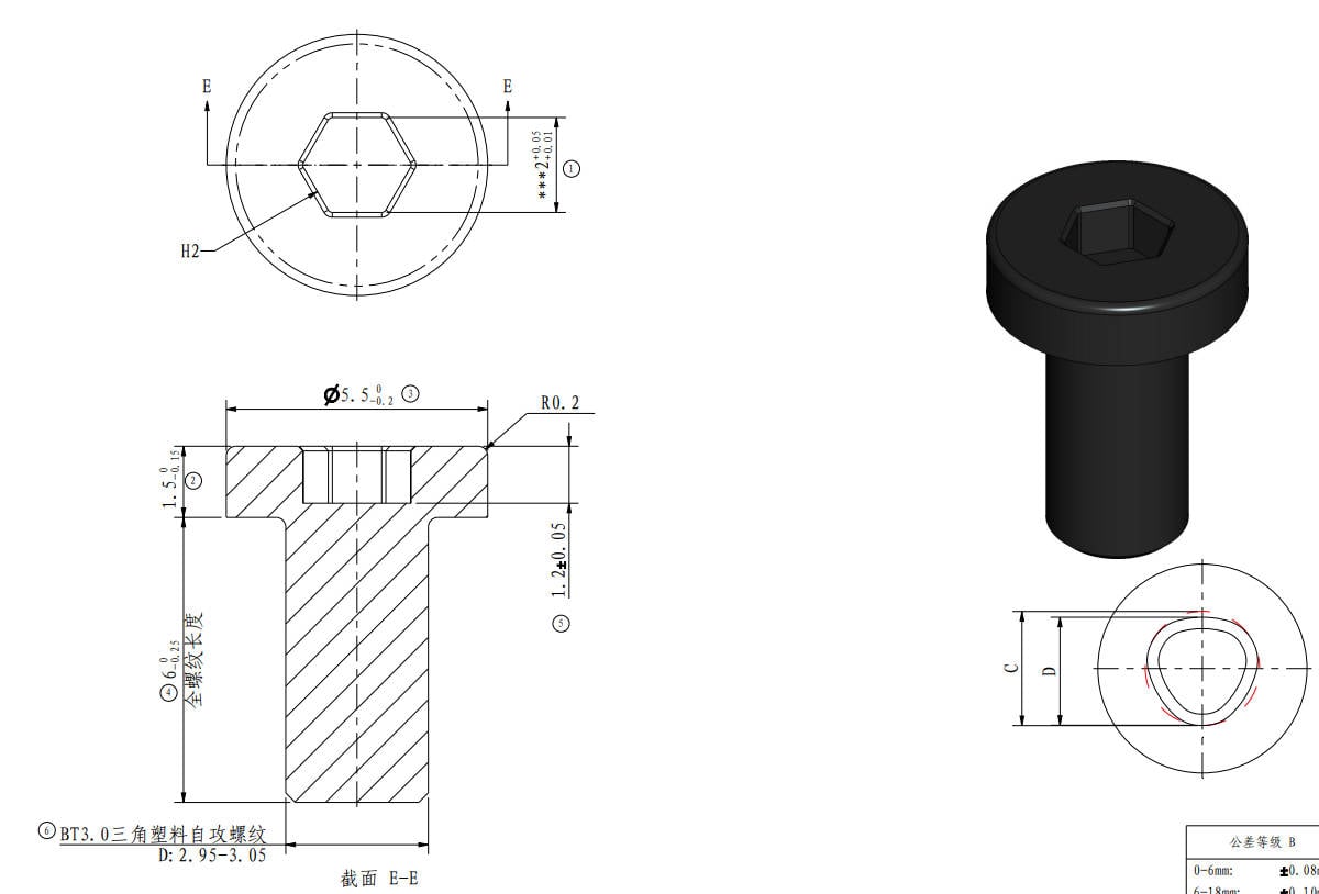
| Screw A | BT3*6 | Metal side panels |
 |
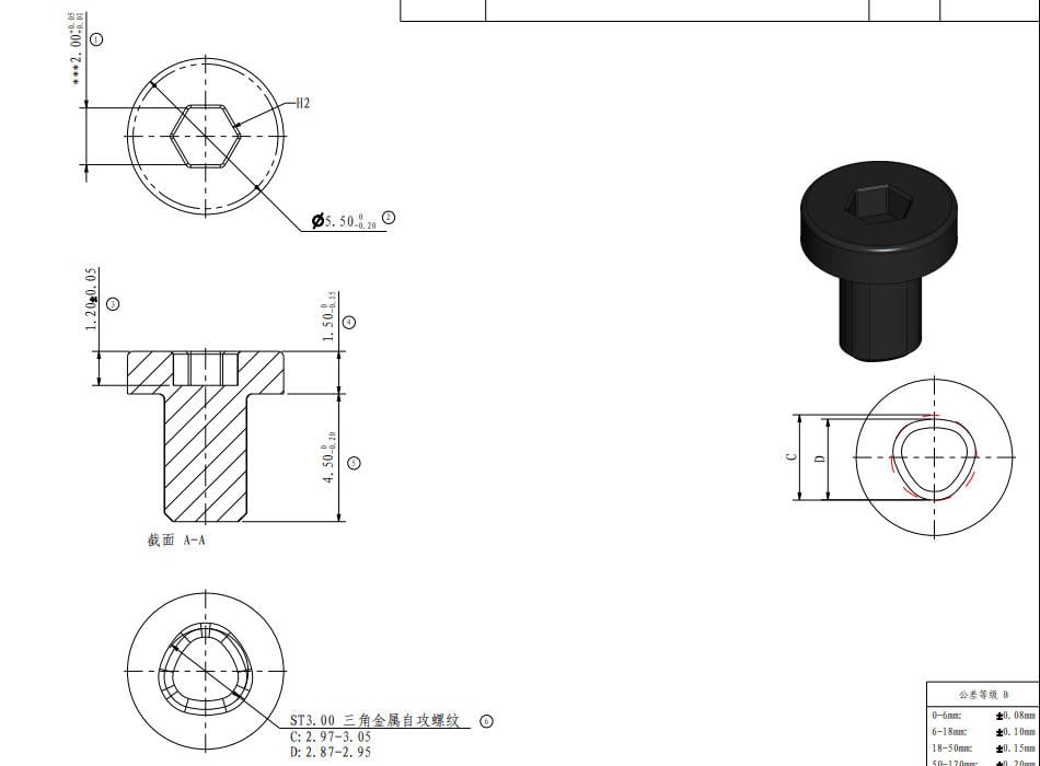
Screw B | ST3*4.5 | Metal side panels, rear panel |
 |
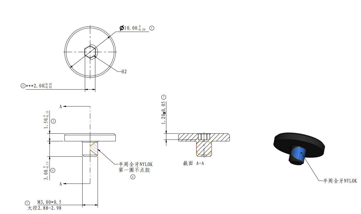
| Screw C | M3*3 | Glass door |
 |
Screw D | BT3*5 | Rear panel |
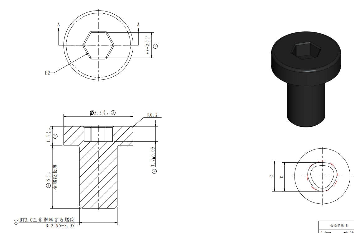 |
| Screw E | MG3*12 |
Aux parts cooling fan |
 |
Screw F | BT3*8 | Tension spring holder |
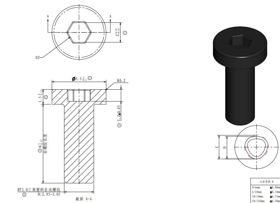 |
| Screw G | M3*6 |
XY tensioner, Extruder |
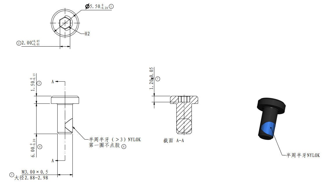 |
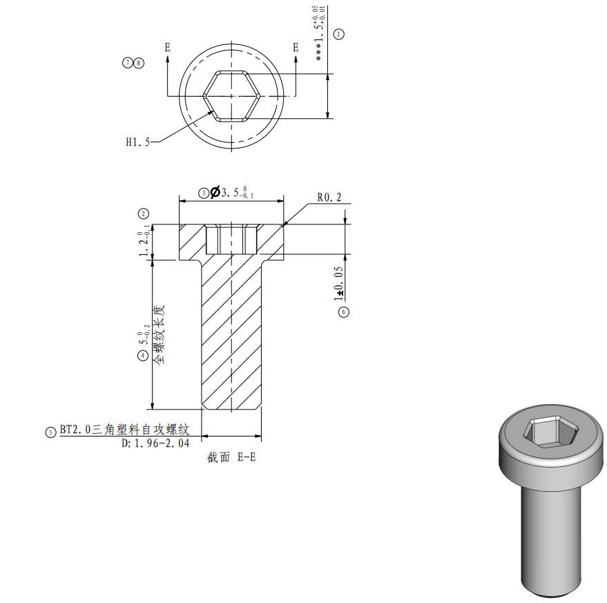
Screw H | BT2*5 | Tool head housing, PCBs |
 |
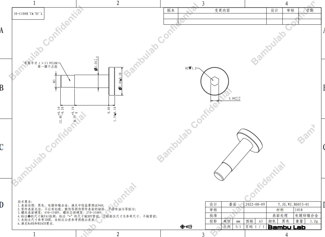
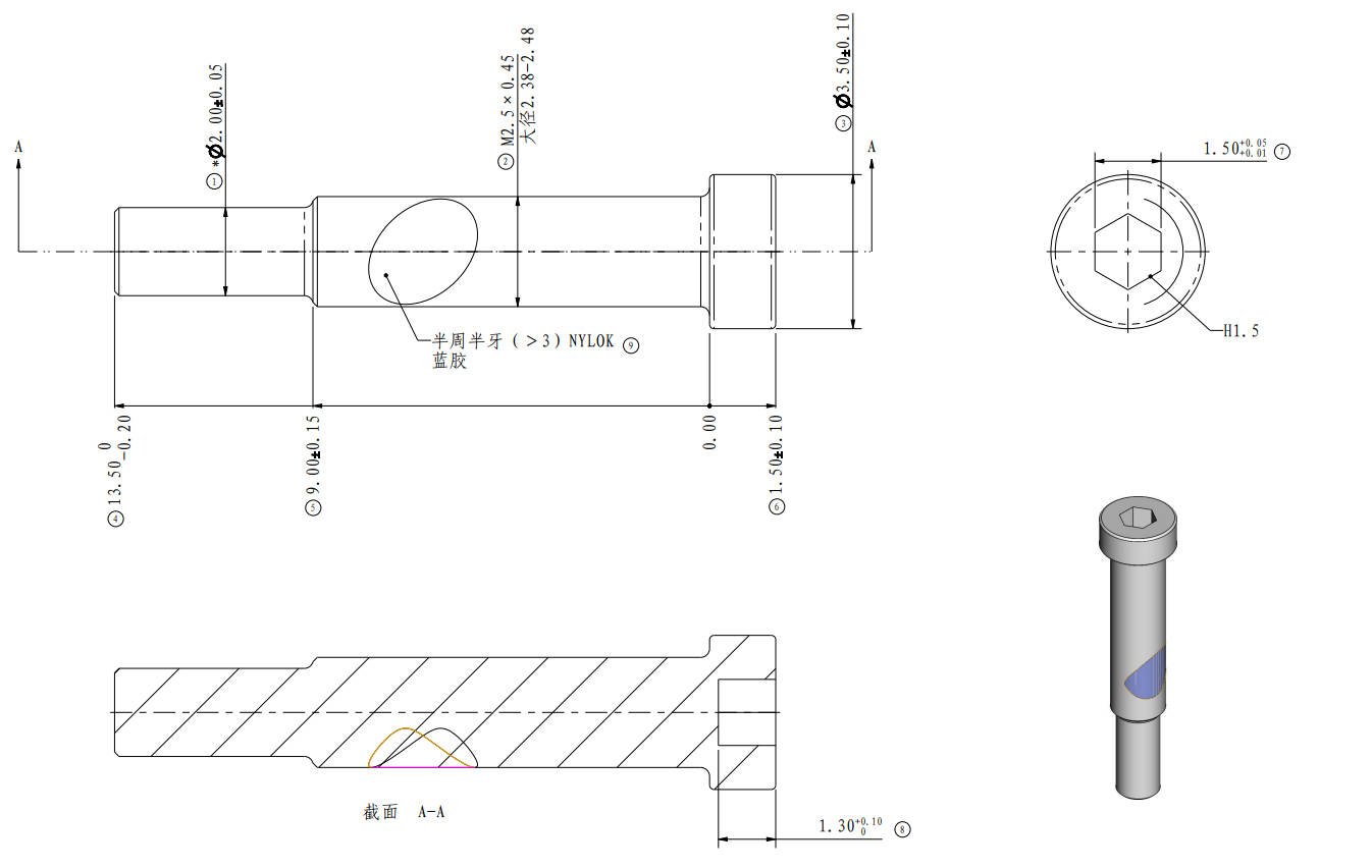
| Screw I | MG2.5*13 | Cutter lever |
 |
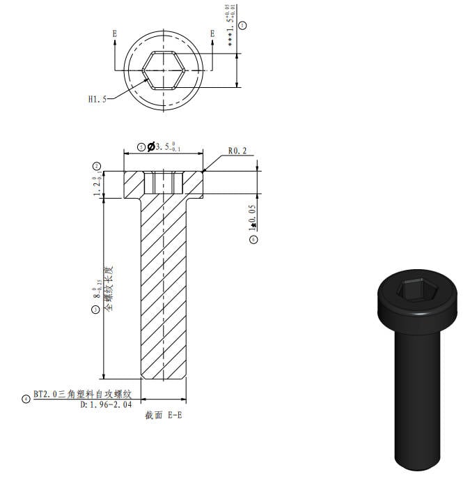
Screw J | BT2*8 | The timing belt, Y slider cover plate. |
 |
¶ Safety Warning
IMPORTANT!
It's crucial to power off the printer before performing any maintenance work on the printer and its electronics, including tool head wires, because leaving the printer on while conducting such tasks can cause a short circuit, which can lead to additional electronic damage and safety hazards.
When you perform maintenane or troubleshooting on the printer, you may be required to disassemble some parts, including the hotend. This process can expose wires and electrical components that could potentially short circuit if they come into contact with each other or with other metal or electronic components while the printer is still on. This can damage the electronics of the printer and cause further damage.
Therefore, it's essential to switch off the printer and disconnect it from the power source before doing any maintenance work. This will prevent any short circuits or damage to the printer's electronics. By doing so, you can avoid potential damage to the printer's electronic components and ensure that the maintenance work is performed safely and effectively.
If you have any concerns or questions about following this guide, open a new ticket in our Support Page and we will do our best to respond promptly and provide you with the assistance you need.
¶ Guide Video
Note:
- For the X1 series, there are different versions of the metal side panels, The video shot here is the new version of the metal side plate. If your printer uses the old version of the metal side plate, there will be more fixing screws. Please refer to the content of the relevant WIKI.
- When replacing the X-axis carbon rods assembly of the P1 series, the front cover needs to be removed. For details, see P1 series front cover installation.
¶ Step 1 - Removing (Assembling) the right panel
If your machine is P1 series, please refer to Replace the Right Plastic Panel - P1 Series.
¶ Step 2 - Removing (Assembling) the glass front door
If your machine is P1 series, please refer to Replace the Front Glass Door.
¶ Step 3 - Removing (Assembling) the left panel
This step includes removing the rear panel and the auxiliary part cooling fan.
If your machine is P1 series, please refer to Replace the Left Plastic Panel - P1 Series.
¶ Step 4 - Removing (Assembling) the XY timing belt
Note: When installing, do not lock the screws at the two tensioning pulleys first, because a calibration for tensioning the belts is required.
¶ Step 5 - Removing (Assembling) the carbon rods
Note: This video is based on the X1 series, but the P1 series will be simpler, so we did not prepare two sets of videos, please pay attention to the differences.
¶ Calibration step after the operation
After replacing the carbon rods, the belts need to be re-tensioned.
- IMPORTANT: Power OFF the printer first.
- Loosen the 4 screws of the belt-tensioner (but DO NOT remove them), then gently move the toolhead back and forth several times, and finally move it to the rear end of the printer. Then, tighten the 4 screws again. The spring system in the belt-tensioner will tighten the belt to the correct tension.
- IMPORTANT: DO NOT overtighten the belt tensioning screws. Doing that can cause damage and will not provide better results. Simply tighten both screws like any other screws and don't over-torque them.
¶ Verify the functionality
- Connect the power and start the printer;
- Run the device self-test process to confirm that the self-test is OK.
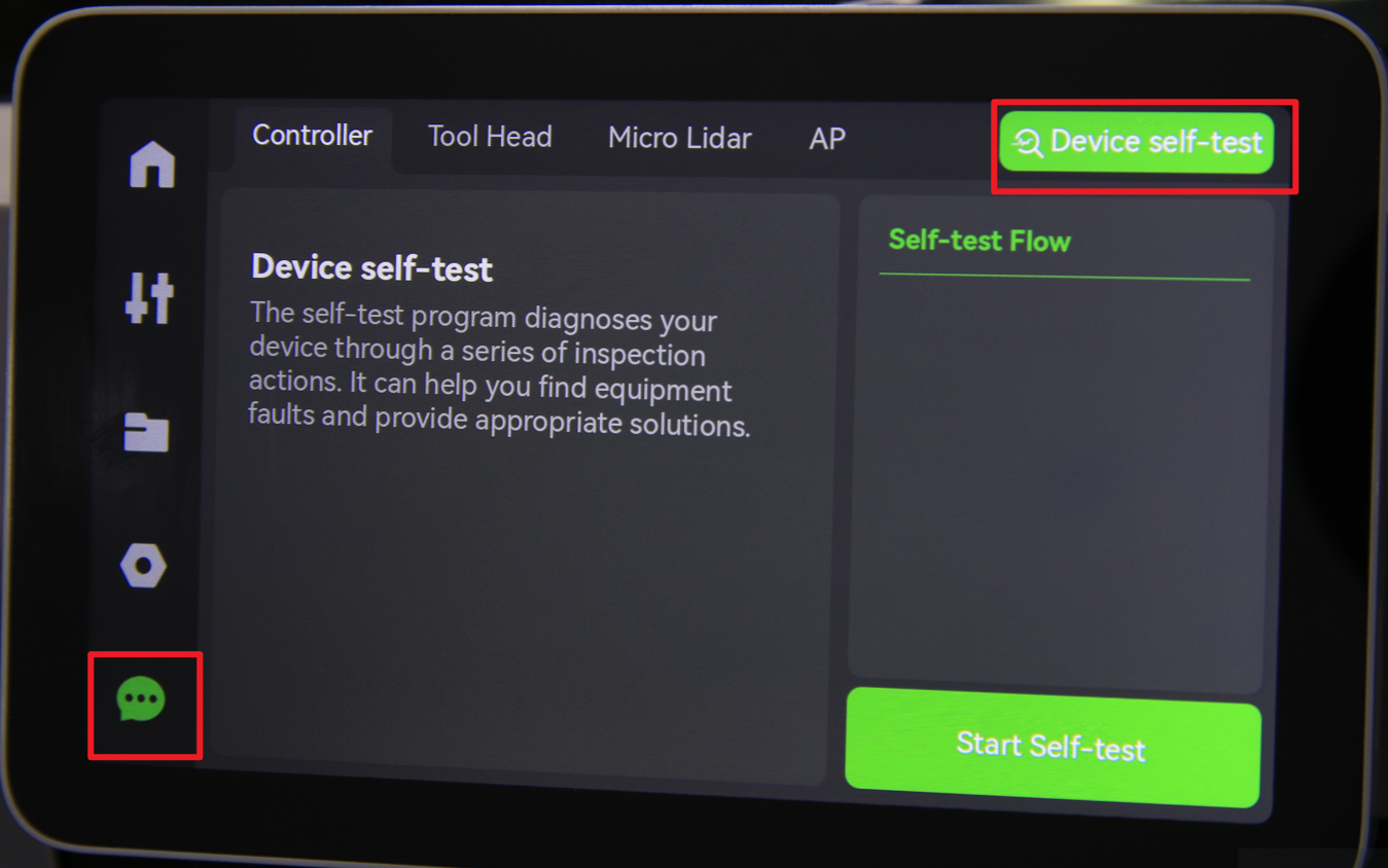
Should you come across any issues, first retrace your steps and check all connections to try again. If problems persist, contact the service team for further assistance.
¶ End Notes
We hope the detailed guide provided has been helpful and informative.
To ensure a safe and effective execution, if you have any concerns or questions about the process described in this article, we recommend submitting a technical ticket regarding your issue.
Please include a picture or video illustrating the problem, as well as any additional information related to your inquiry.