¶ Toolhead Front Carriage
Hereinafter, we will present the detailed steps for replacing the toolhead front carriage.
¶ When to use?
- The fixing nut of the extruder is loose.
- The filament cutter shaft is bent.
- Recommended by Bambu Lab customer support
¶ Tools and materials needed
- Toolhead Front Carriage
- H2.0 hex wrench
- H1.5 hex wrench
- 30 minutes
¶ Safety Warning
It's crucial to power off the printer before conducting any maintenance work, including work on the printer's electronics and tool head wires. Performing tasks with the printer on can result in a short circuit, leading to electronic damage and safety hazards.
During maintenance or troubleshooting, you may need to disassemble parts, including the hotend. This exposes wires and electrical components that could short circuit if they contact each other, other metal, or electronic components while the printer is still on. This can result in damage to the printer's electronics and additional issues.
Therefore, it's crucial to turn off the printer and disconnect it from the power source before conducting any maintenance. This prevents short circuits or damage to the printer's electronics, ensuring safe and effective maintenance. For any concerns or questions about following this guide, open a new ticket in our Support Page and we will do our best to respond promptly and provide the assistance you need.
¶ Remove the old toolhead front carriage
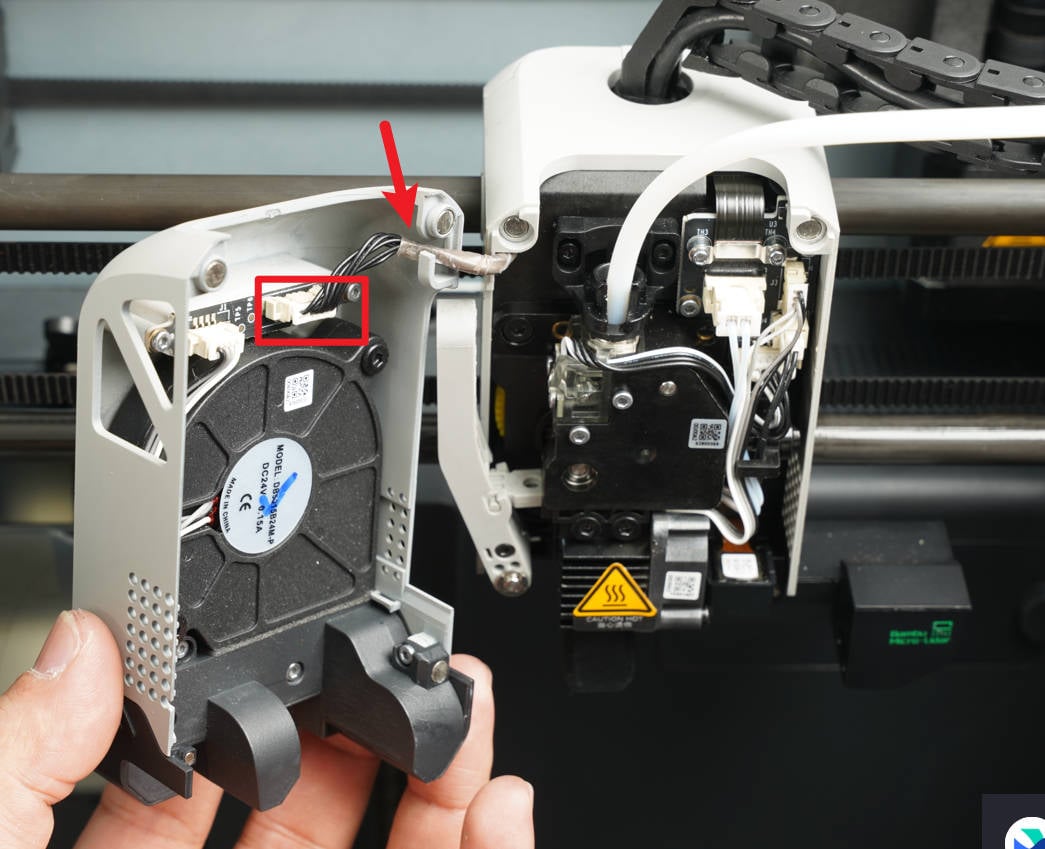
¶ 1.Remove the front housing assembly
Open the front housing assembly by carefully separating the components. Disconnect the connecting cable and proceed to remove the front housing assembly.
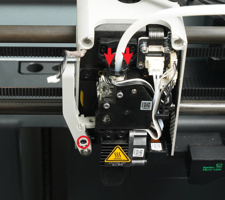
¶ 2.Loosen the cutter lever
Press the joint, then disconnect the PTFE tube of the extruder. Use an H1.5 hex socket wrench to loosen the cutter lever screws and remove the Cutter lever.
 |
 |
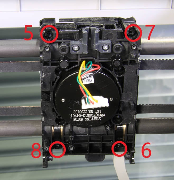
¶ 3.Remove the tool head housing
Remove the 8 screws (BT2-5) fixing the tool head housing with the H1.5 hex wrench on both sides, and remove the tool head rear cover and middle frame.
 |
 |
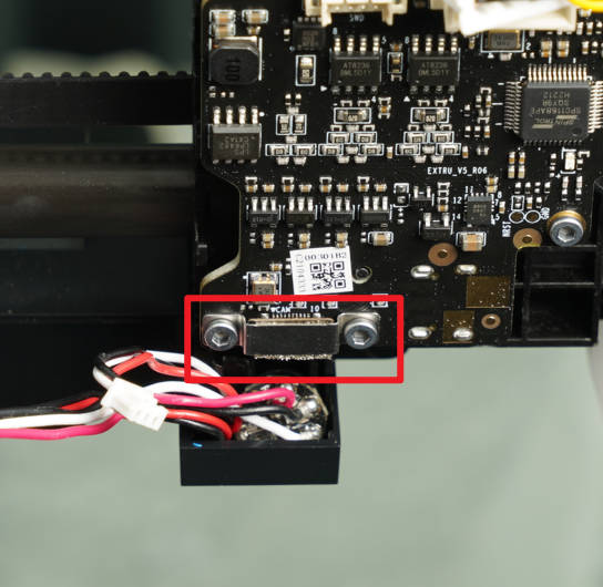
¶ 4.Disconnect the USB cable
Disconnect the USB cable from the extruder main board, and then remove the main board along with the bracket from the tool head.
¶ 5.Remove the connecting FPC
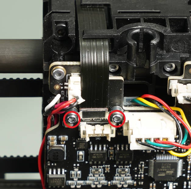
Unscrew the screws at both ends of the connecting FPC Cable using the H1.5 hex key, remove the brackets, disconnect the cable, and then remove it from the tool head.
Note: The 4 screws used in this step are smaller in size. Be cautious not to overtighten the screws to avoid breakage, and make sure not to mix them with other screws.
 |
 |
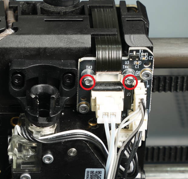
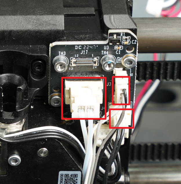
¶ 6.Remove the interface board
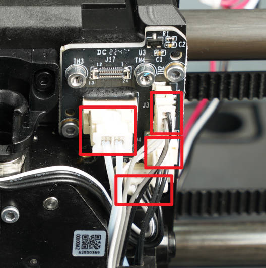
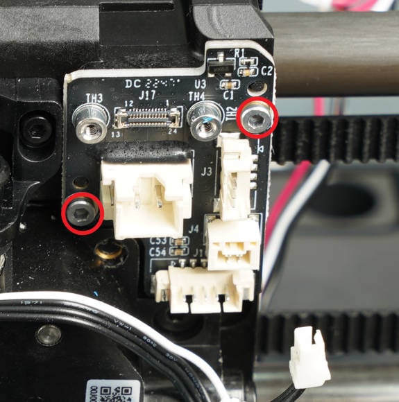
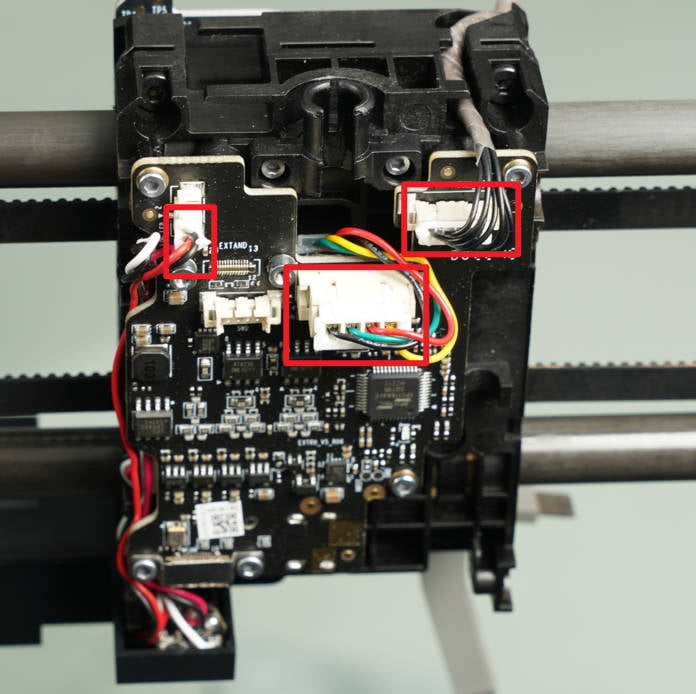
Disconnect the 4 cables that are connected to the interface board. Then, using an H1.5 hex wrench, remove the two screws securing the interface board. Finally, remove the interface board from its position.
 |
 |
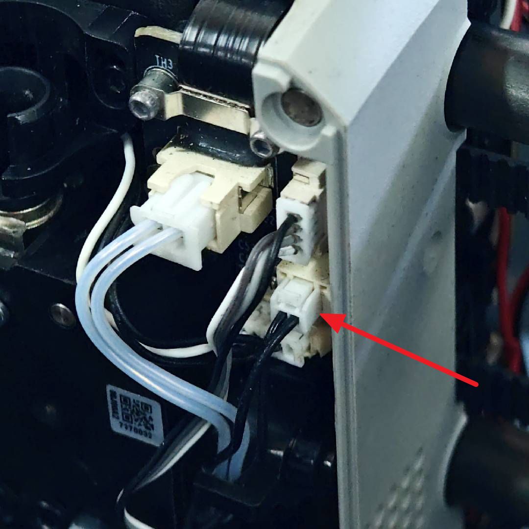
Warnings: The thermistor plug is equipped with a buckle/latch (which differs from the fan and heater plugs). To disconnect it, you need to push the latch to unlatch it instead of pulling on the wires/plug, as this may cause the entire PCB connector to come off.
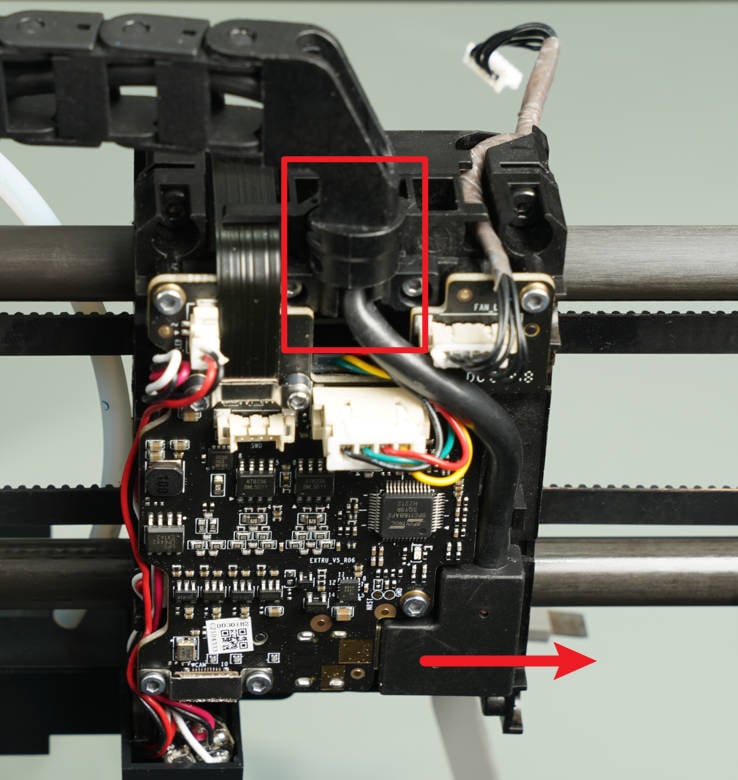
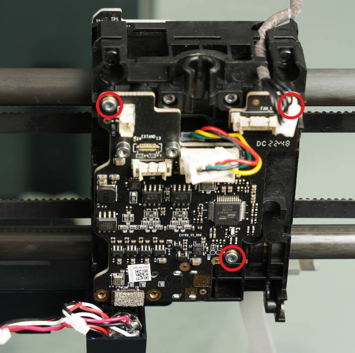
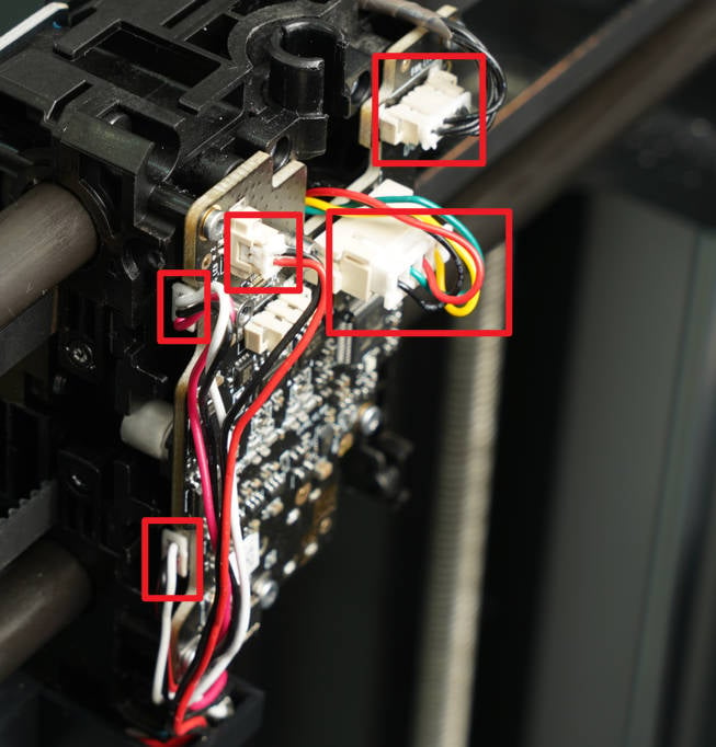
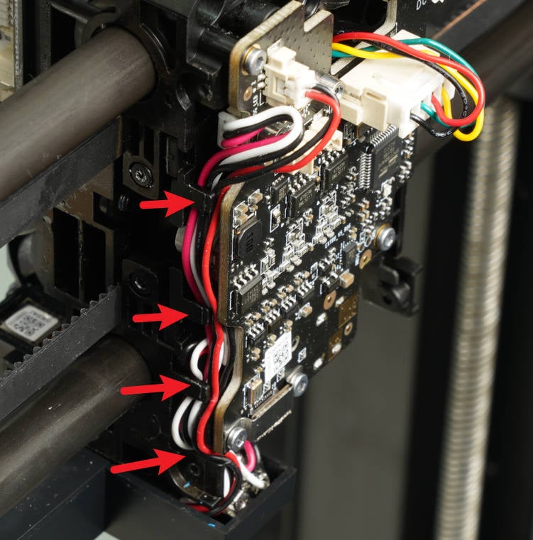
¶ 7.Remove the extruder main board
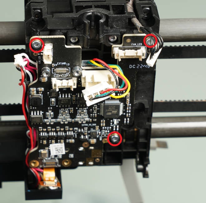
Disconnect the 3 cables that are connected to the extruder main board. Then, using an H1.5 hex key, remove the three screws securing the extruder main board. Turn the extruder main board to the left and disconnect the two laser cables. Finally, remove the extruder main board from its position.
 |
 |
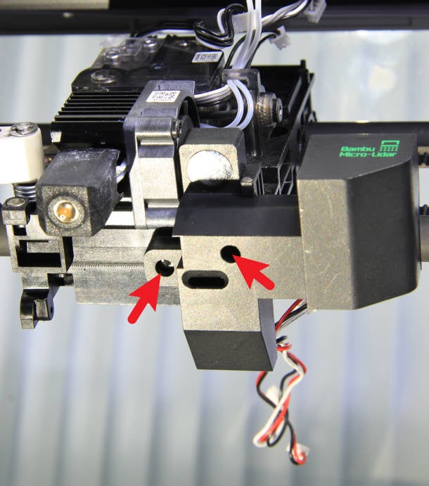
¶ 8.Remove the Bambu micro lidar
Remove 2 screws with an H1.5 hex wrench and remove the micro lidar assembly.
 |
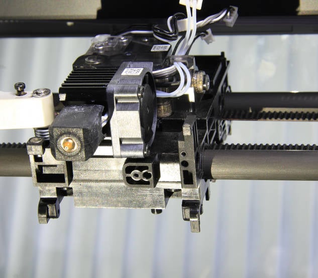 |
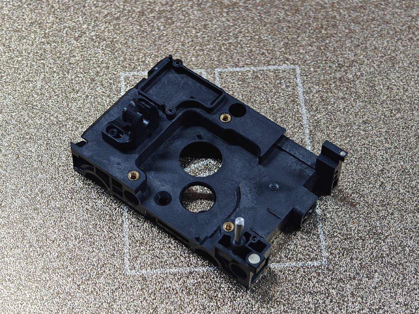
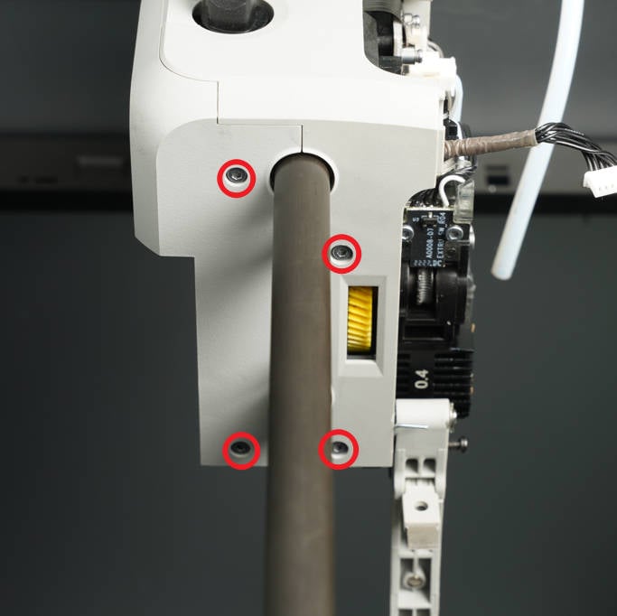
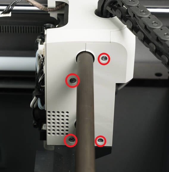
¶ 9.Remove the front cover assembly of the toolhead slider
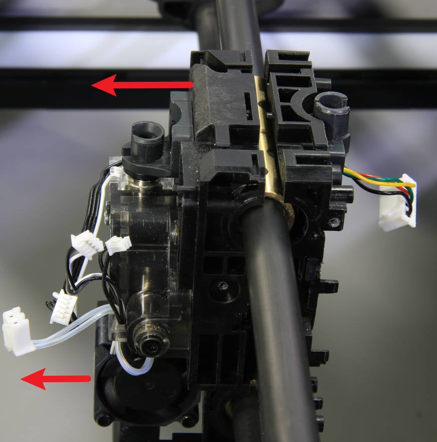
Remove 8 screws (BT3-8) with an H2.0 hex wrench in sequence.
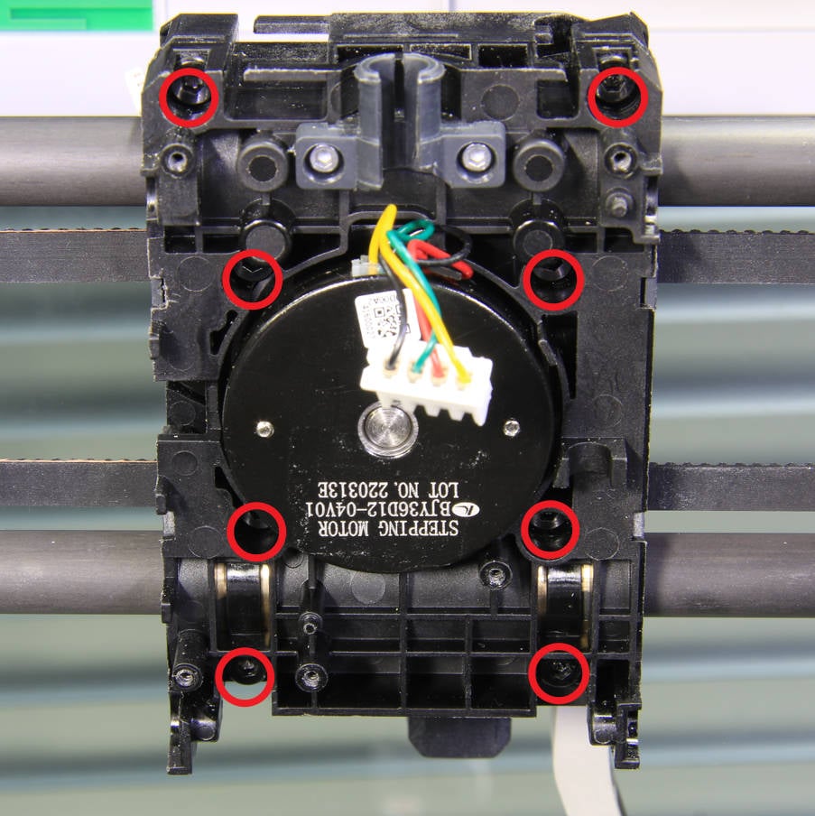
Remove the front cover assembly (with the extruder) of the toolhead.
 |
 |
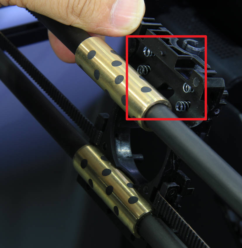
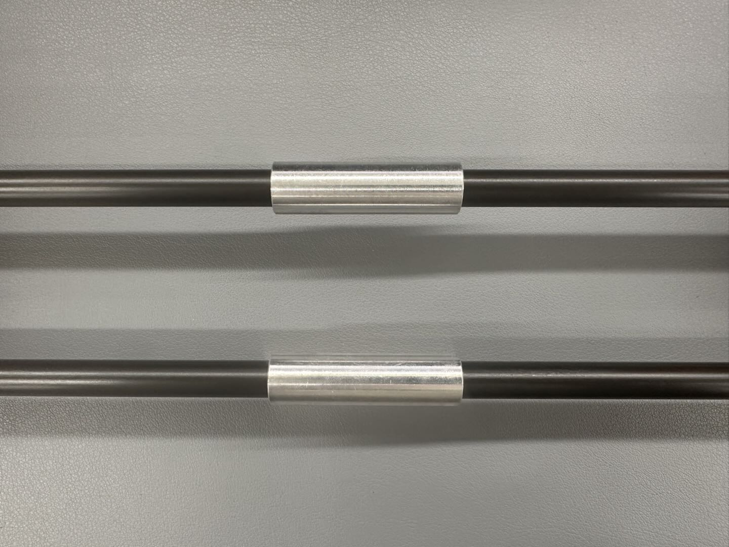
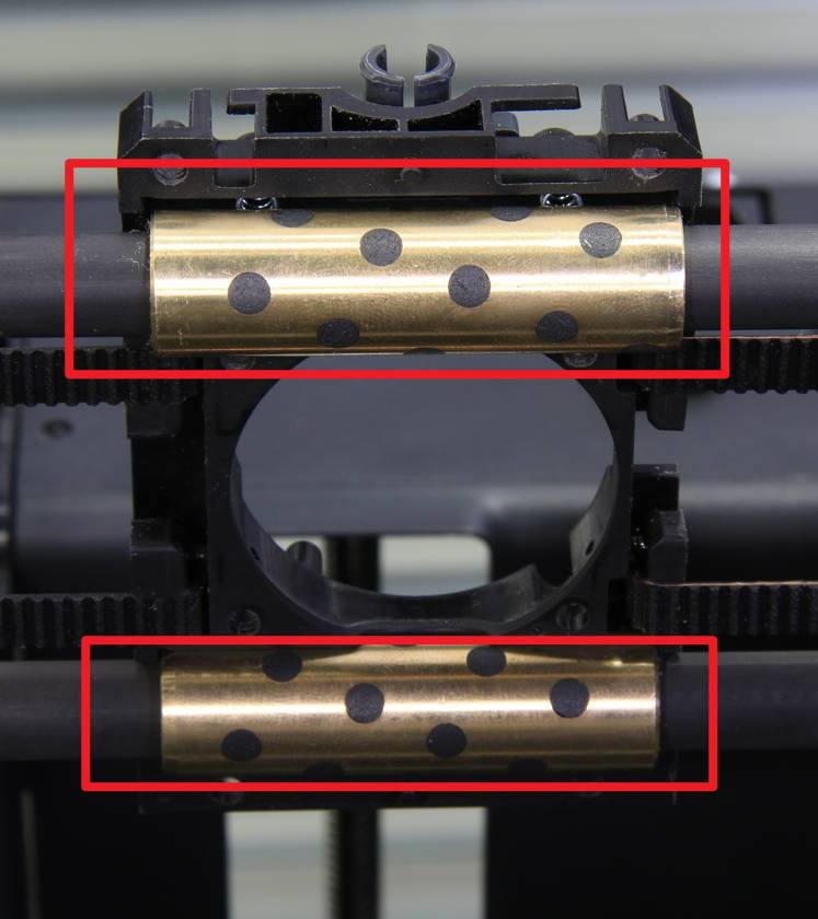
Note: In the new version, aluminum sleeves are used. The rear cover of the toolhead pulley is equipped with 4 springs. To prevent them from falling off or getting lost, take necessary precautions.
 |
 |
¶ 10.Remove the extruder
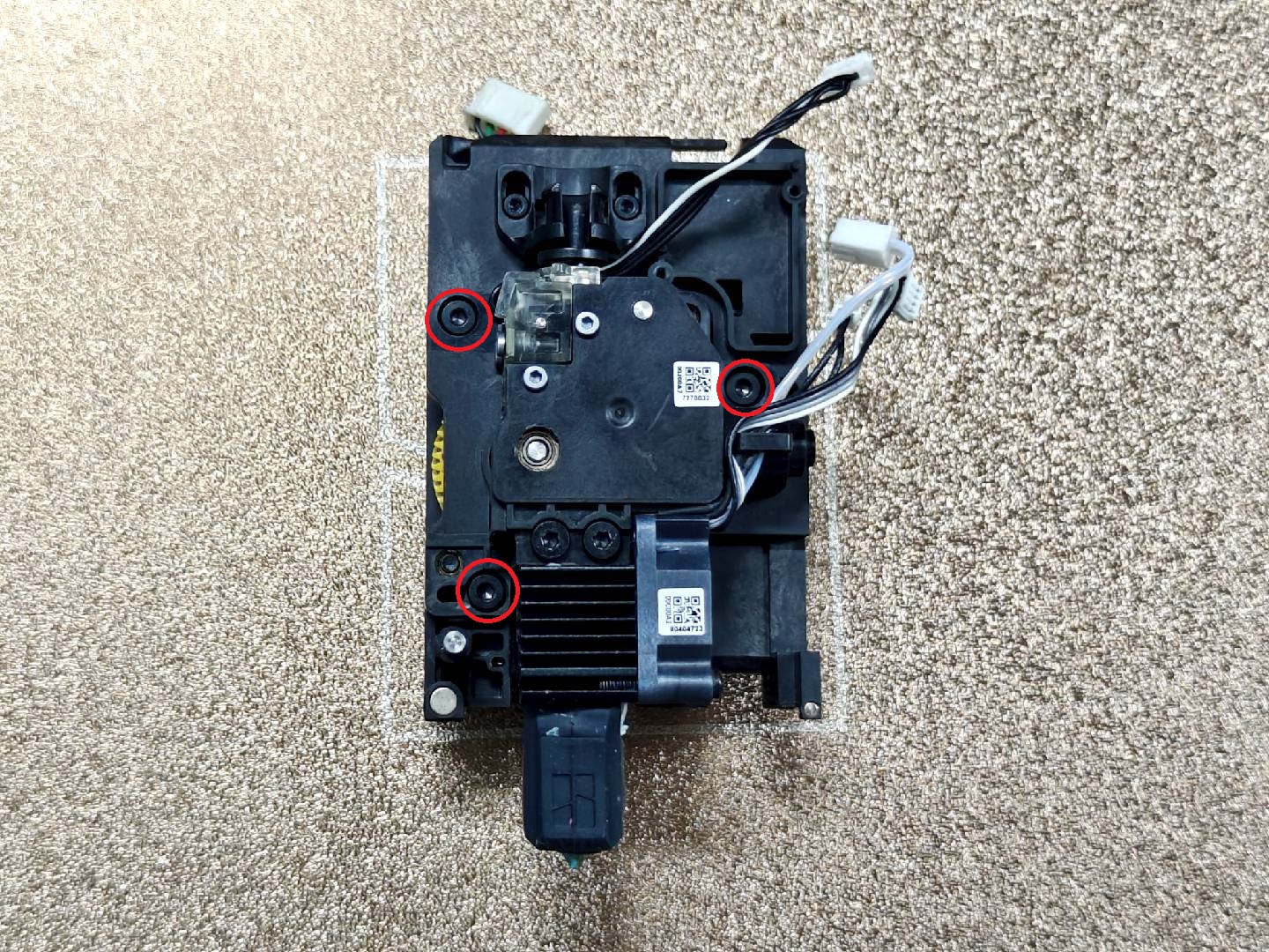
Remove the 3 screws (M3-6) with an H2.0 hex wrench, and remove the extruder and the hot end.
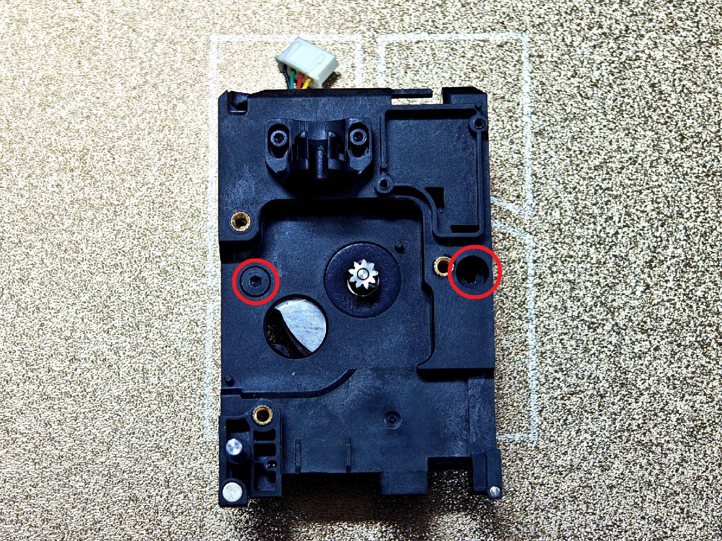
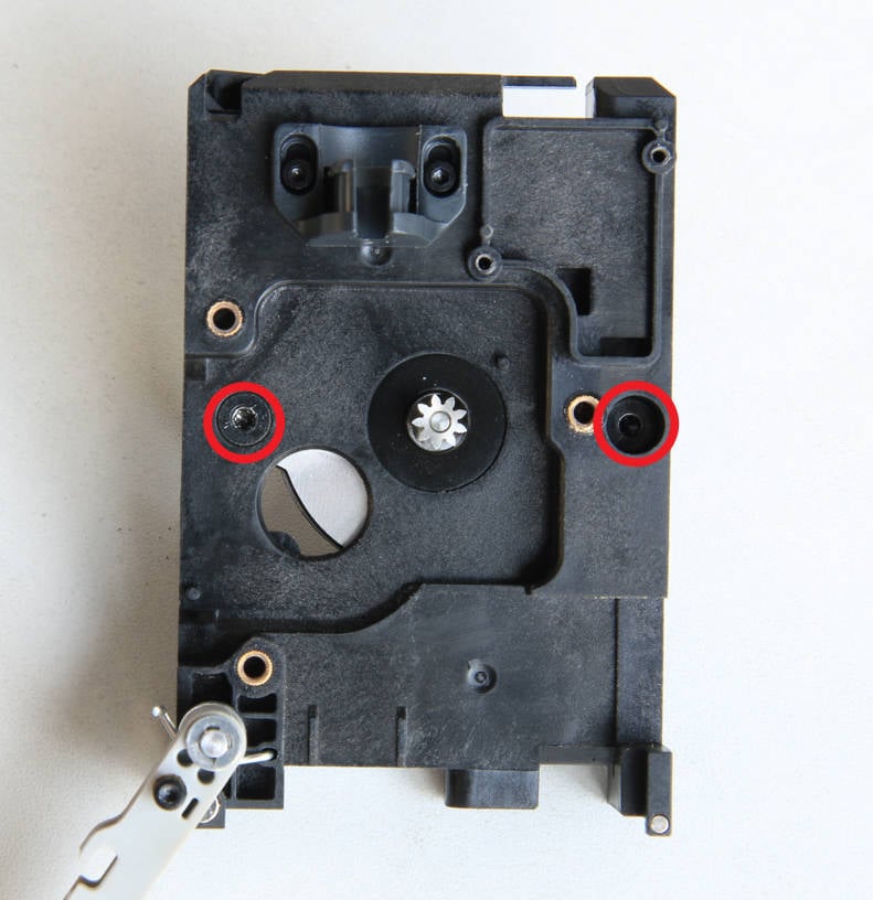
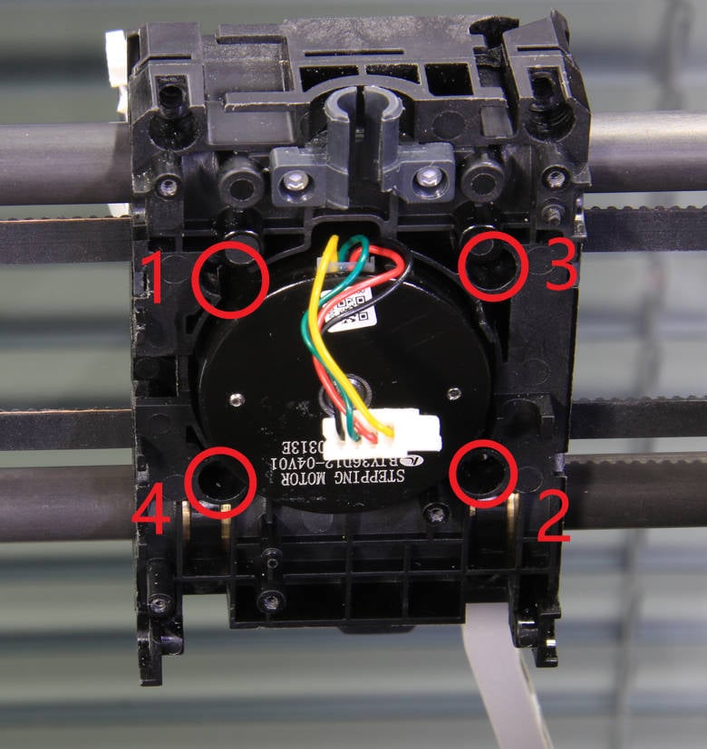
Remove 2 screws with an H2.0 hex wrench and remove the extruder motor.
¶ Install the new toolhead front carriage
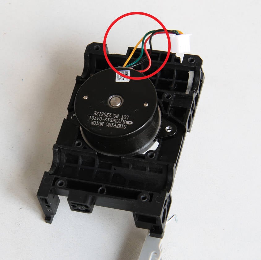
¶ 1.Install the extruder motor
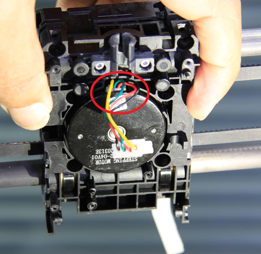
Install the extrusion motor onto the front cover of the new toolhead front carriage. Keep the cable on top. Then lock in two screws to fix the motor. At the same time, you can install the filament cutter lever.
 |
 |
¶ 2.Install the extruder
Install the extruder and the hot end together on the front cover of the slider, and then secure it with 3 screws (M3-6).
¶ 3.Install the front cover assembly of the toolhead
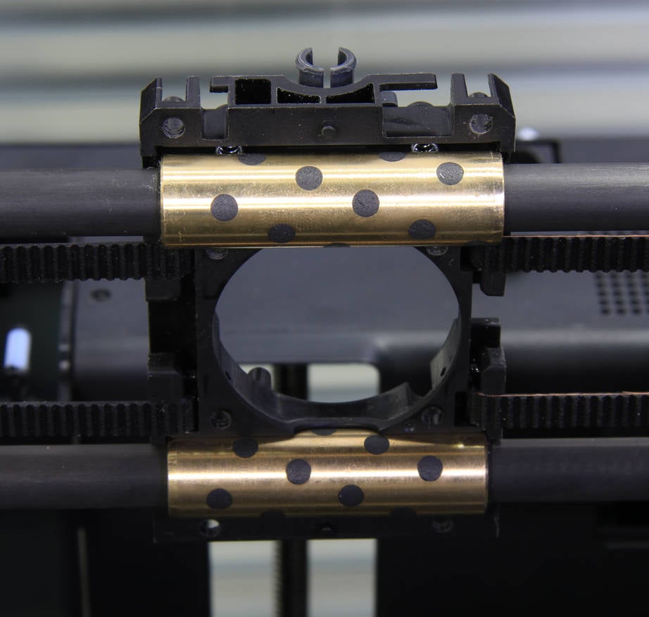
Before installation, ensure that the springs are correctly positioned and that both copper sleeves are inserted into the corresponding grooves on the back cover of the slider. Then, carefully install the front cover assembly of the slider, being cautious not to press against the motor cable.
 |
 |
 |
 |
¶ 4.Install the Bambu micro lidar
Install the Bambu micro lidar under the toolhead and secure it with 2 screws (BT2-5).
|
|
¶ 5.Install the extruder main board
Install the tool head system LED light cable.
 |
 |
Install the extruder main board onto the tool head and secure it with three screws (BT2-5). Then, connect the camera flexible cable and install the bracket. Finally, use two screws to lock the bracket in place.
 |
 |
Connect the cable (extruder main board).
 |
 |
¶ 6.Install the interface board
Install the interface board onto the tool head and secure it with two screws. Next, connect the cable of the Hall board (extruder). It is recommended to reinforce the connection with silicone glue. Afterward, connect the 3 hotend cables.
|
 |
Install the connecting FPC;We strongly recommend you carefully check the BTB connectors on the FPC and the board before installation. The female BTB connectors must correspond to the male BTB connectors.
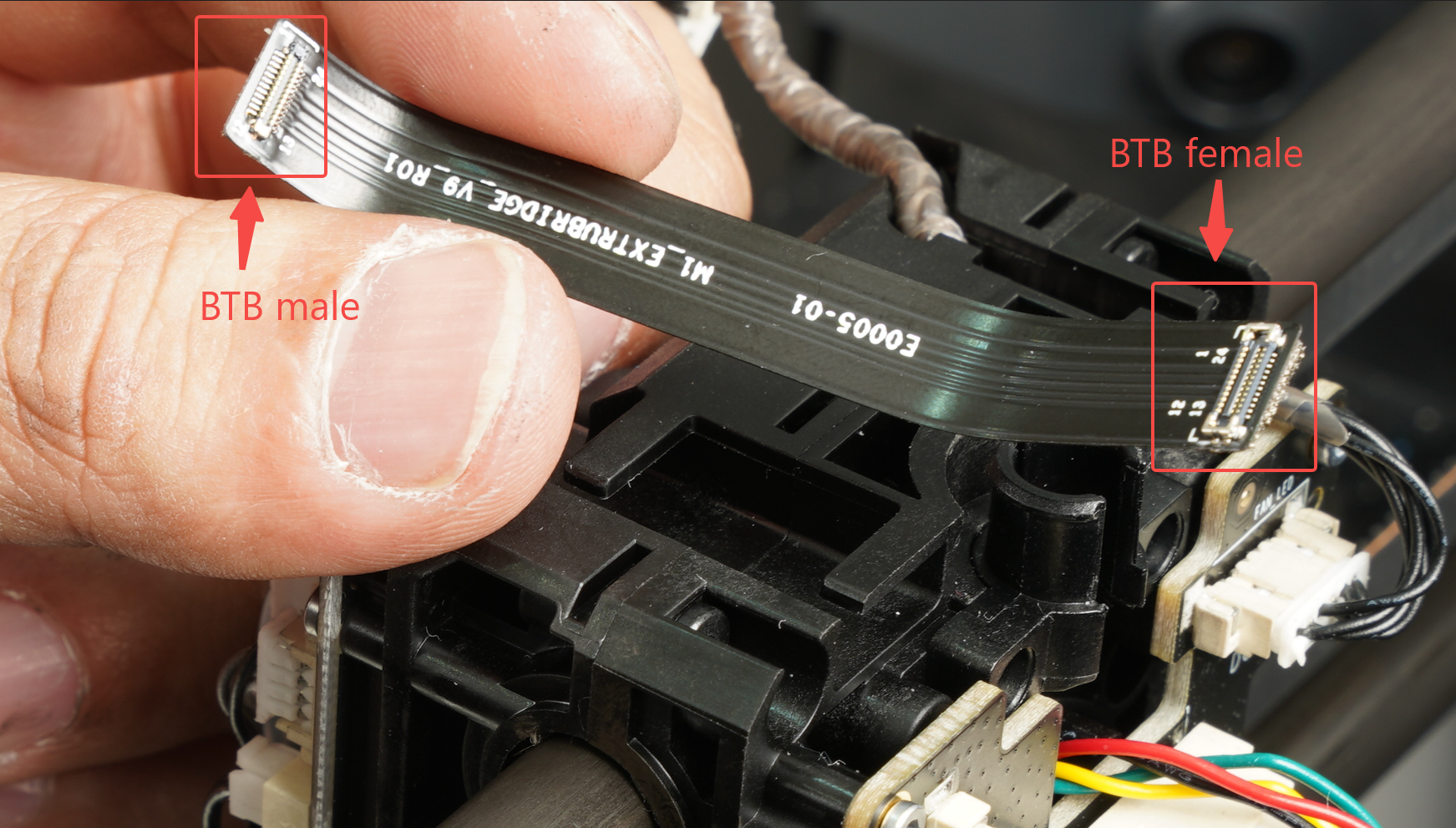
After confirming the direction of connecting the flat cable, install it into the slot above the tool head. Then connect them to the connectors of the interface board and the extruder main board, and reinforce them with crimping brackets and screws.
|
|
Note: The 4 screws used here are smaller in size. Avoid tightening the screws vigorously to prevent the screws from breaking and cannot be mixed with other screws.
¶ 7.Connect the USB cable
Connect the USB cable to the extruder main board, press the USB cable into the cable base, and then mount the cable bracket in place.
¶ 8.Install the tool head housing
Install the middle frame and rear cover of the tool head, and lock four screws (BT2-5) on both sides, respectively.
|
|
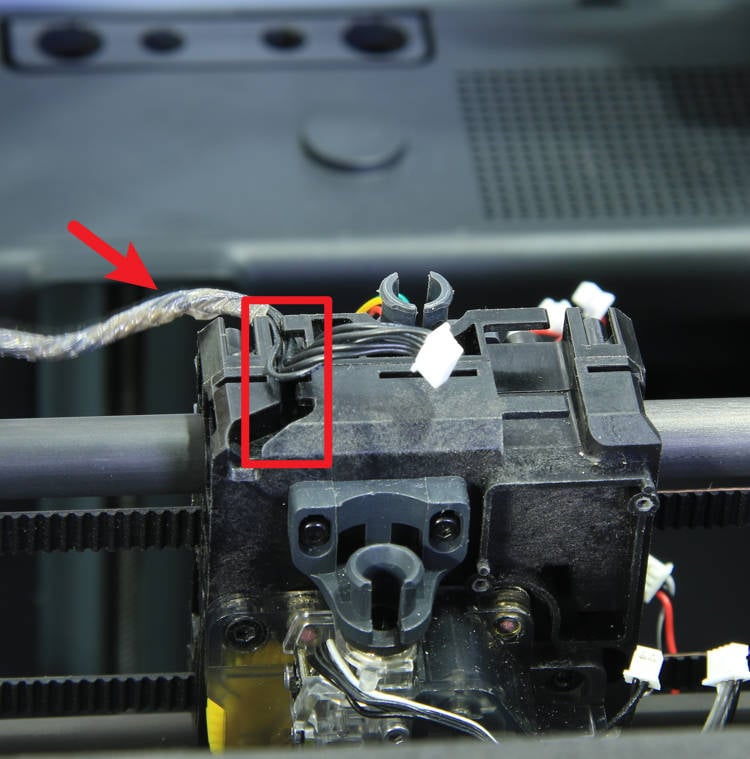
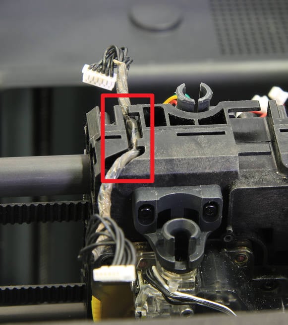
¶ 9.Install the cutter lever and the front cover
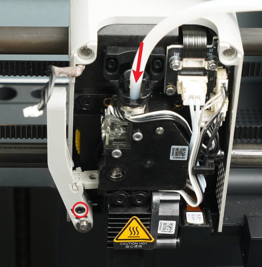
Lift the cutter lever by hand, slide the cutter into the extruder along the cutter slot, lock the fixing screw, and connect the PTFE tube.
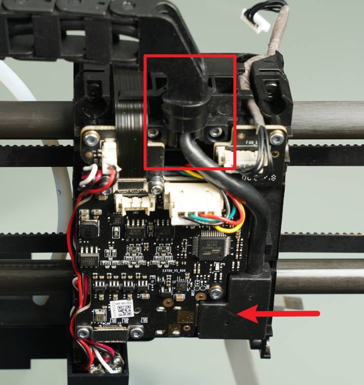
Connect the front cable as shown in the figure below and then close the front housing.
 |
|
¶ How to verify completion/success
Connect the printer to the power supply. First, try increasing the hotend temperature and turning on the part cooling fan, then observe whether the temperature rises and the fan spins normally.
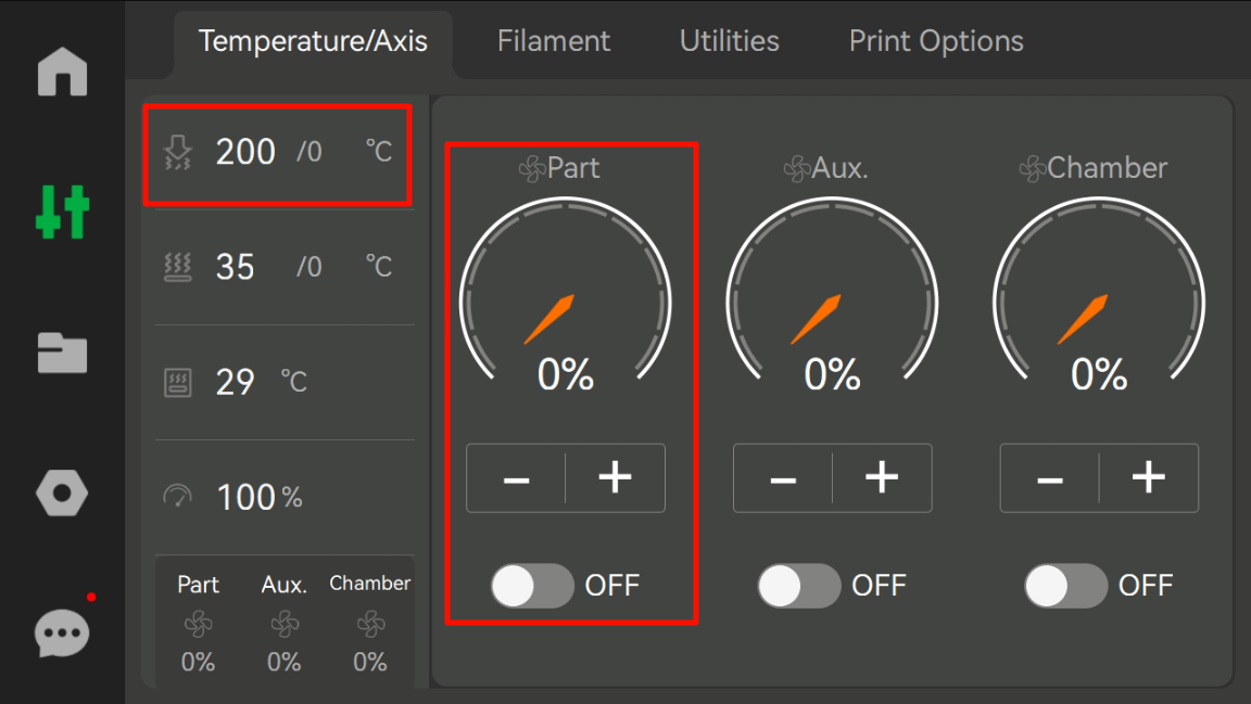
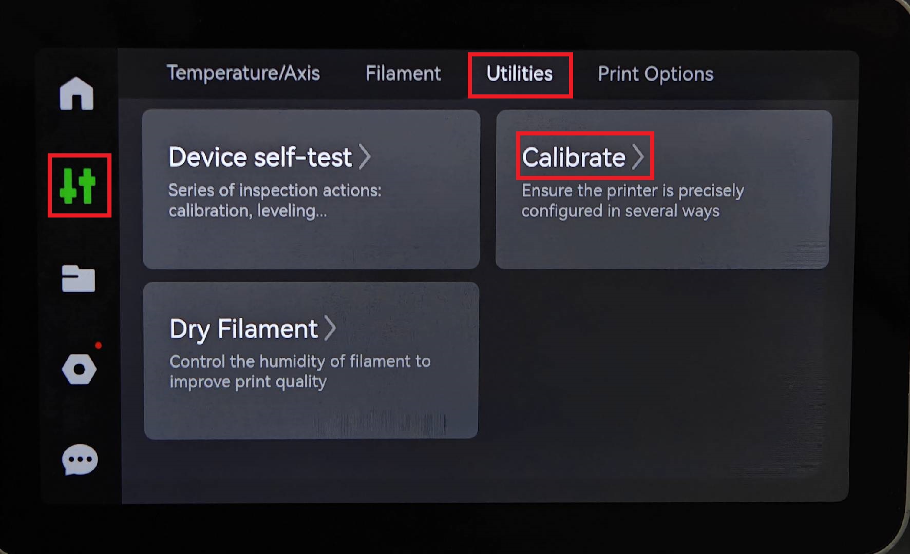
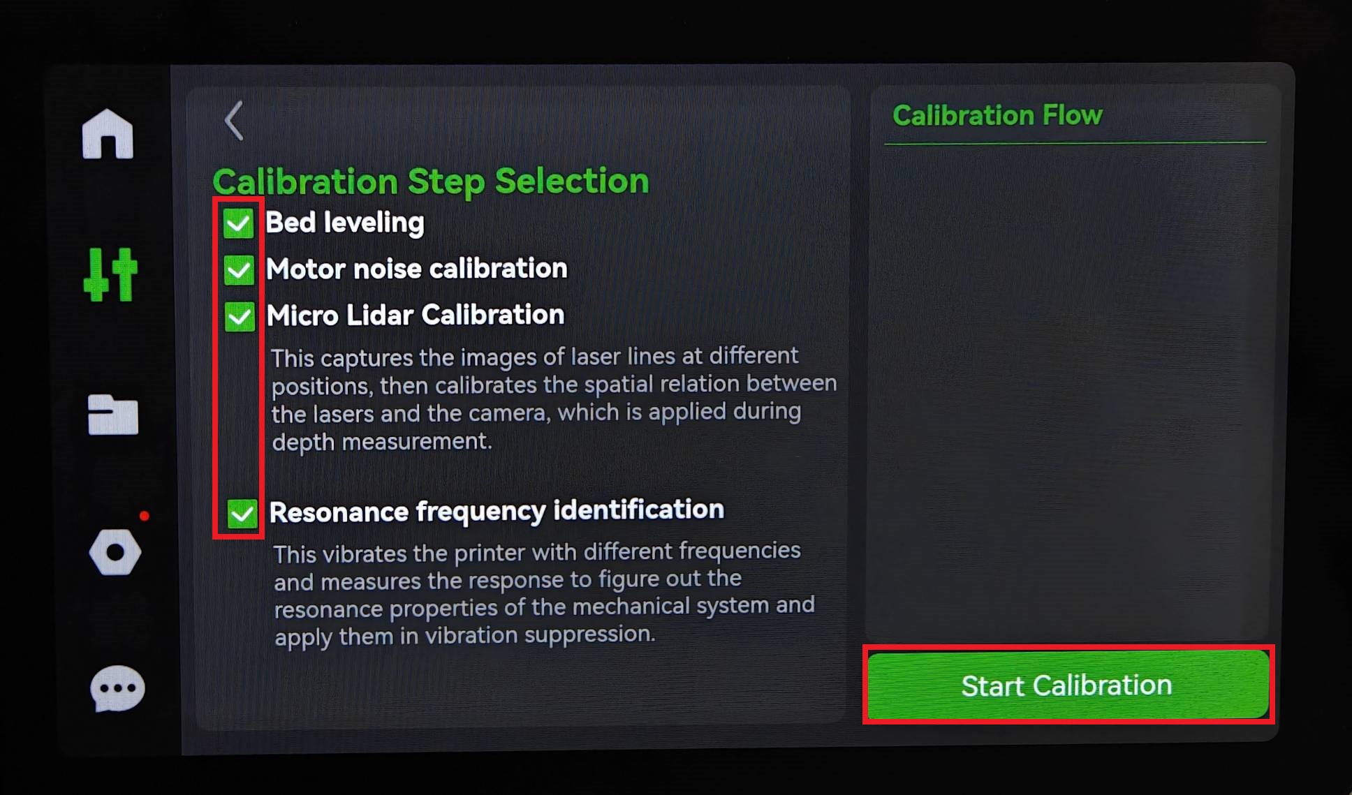
After that, you can proceed to calibrate the printer.
Calibration is considered successful if there are no abnormalities. Then, initiate the print test.
 |
 |
¶ End Notes
We hope the detailed guide provided has been helpful and informative.
If this guide does not solve your problem, please submit a technical ticket, we will answer your questions and provide assistance.
If you have any suggestions or feedback on this Wiki, please leave a message in the comment area. Thank you for your support and attention!