¶ Overview of the Issue
Sometimes, obvious horizontal lines appear on the printed model surface, commonly called “layer lines”. These lines usually occur in the following scenarios:
- Cross-sectional transition areas (like the bottom of a box or places where the section changes)
- Flow rate change zones (like outer walls right after bridging)
- Toolhead or color switches (in multi-color prints with uneven cooling)
This article will analyze causes for each case and provide solutions to reduce them.
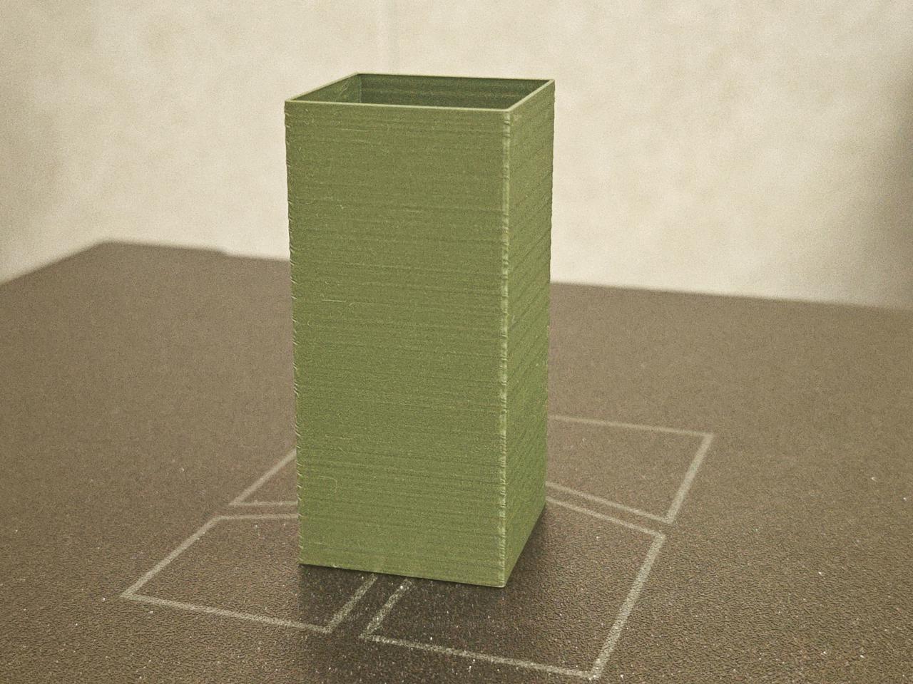
¶ 1. Cross-Section Layer Lines (e.g. Boxes, 3D Benchy)
¶ Cause Analysis
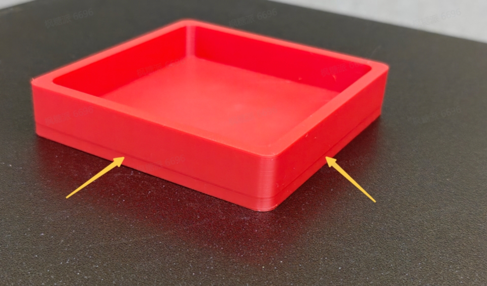
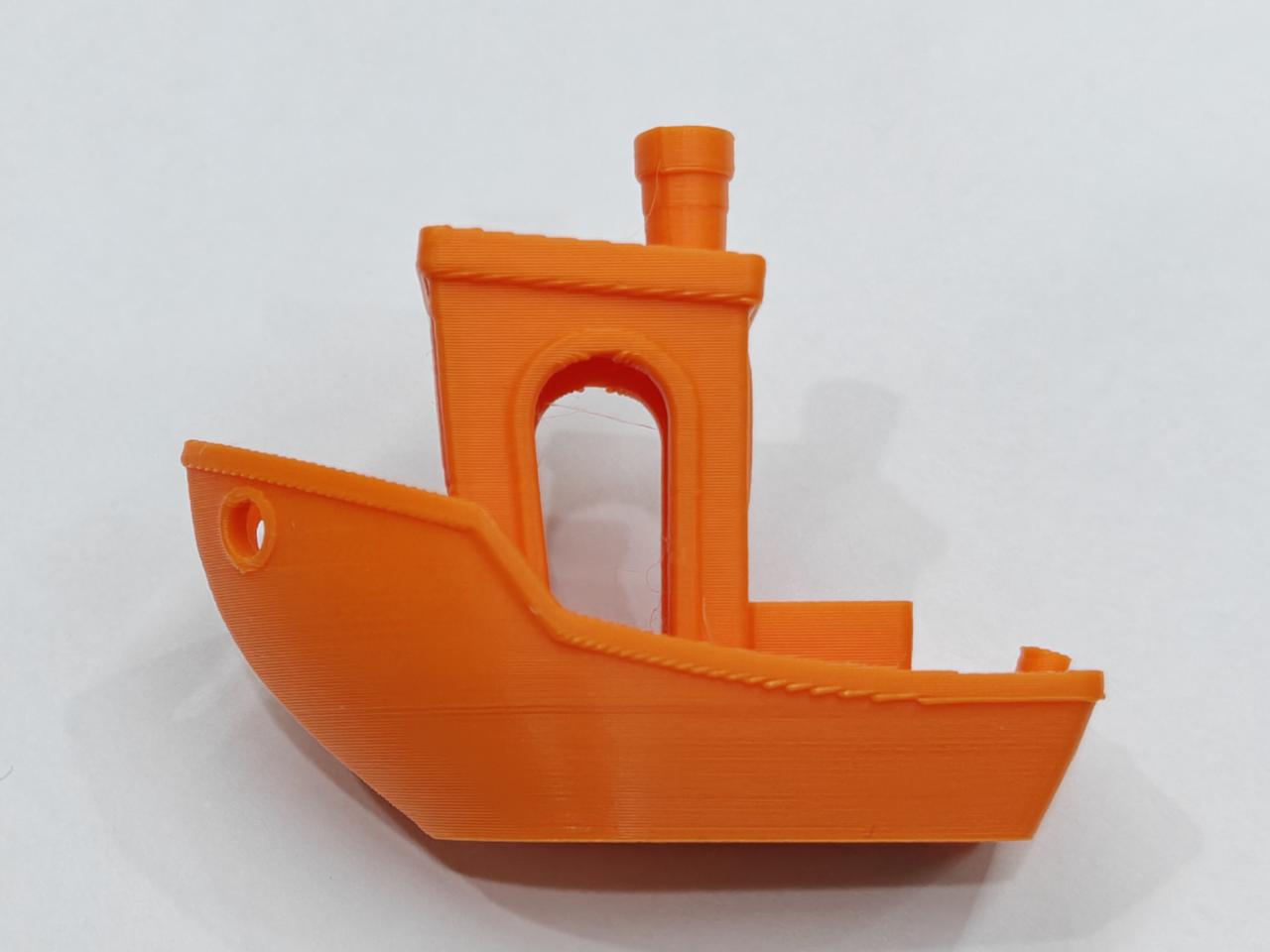
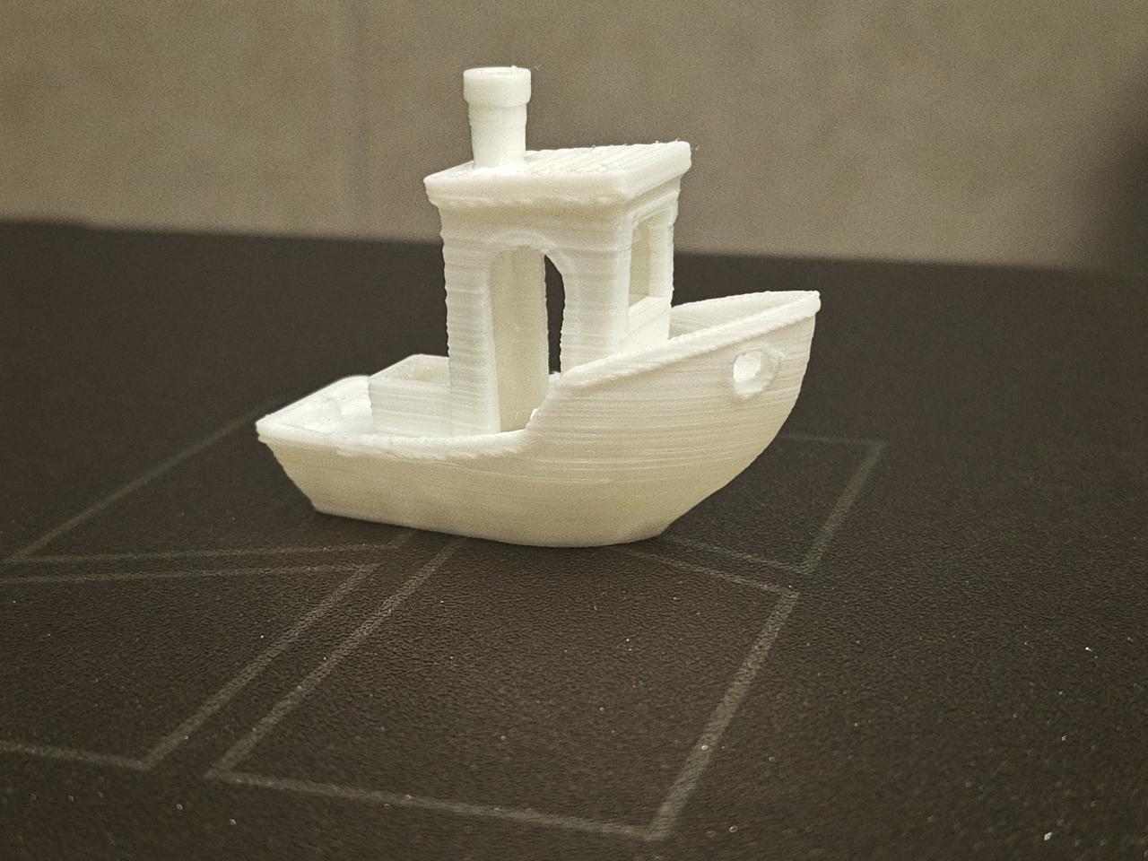
On box-type models, at the junction between the large bottom surface and thin walls, or in the waist area of boat models, abnormal ring-shaped ridges may appear on the outer wall surface. This phenomenon is commonly referred to as variable cross-section layer lines.
Case Study (Box Type):
 |
 |
- Close-up observation: The raised ridges are concentrated in the last few top layers, while the earlier layers show obvious signs of material shrinkage.
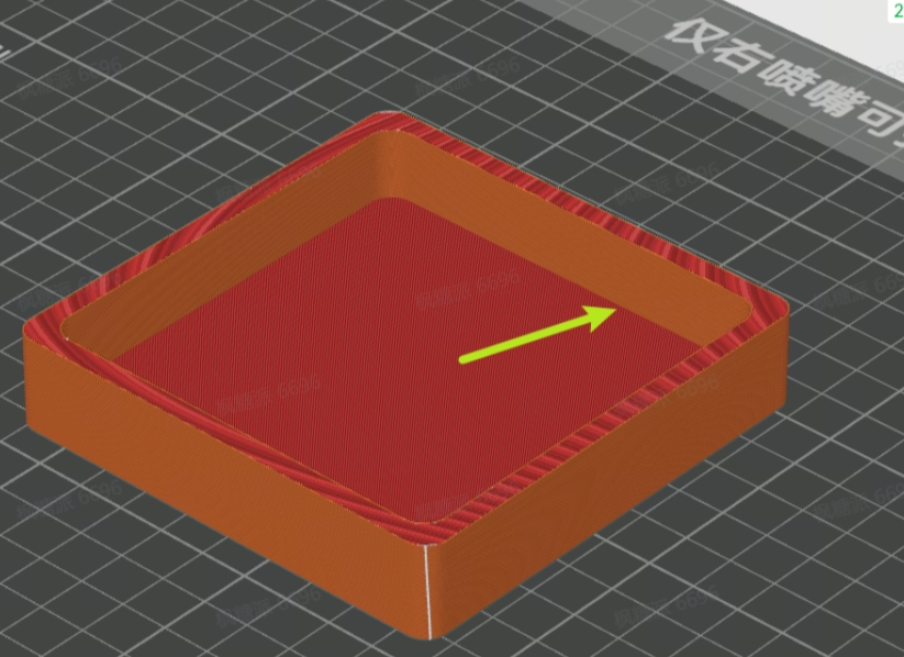
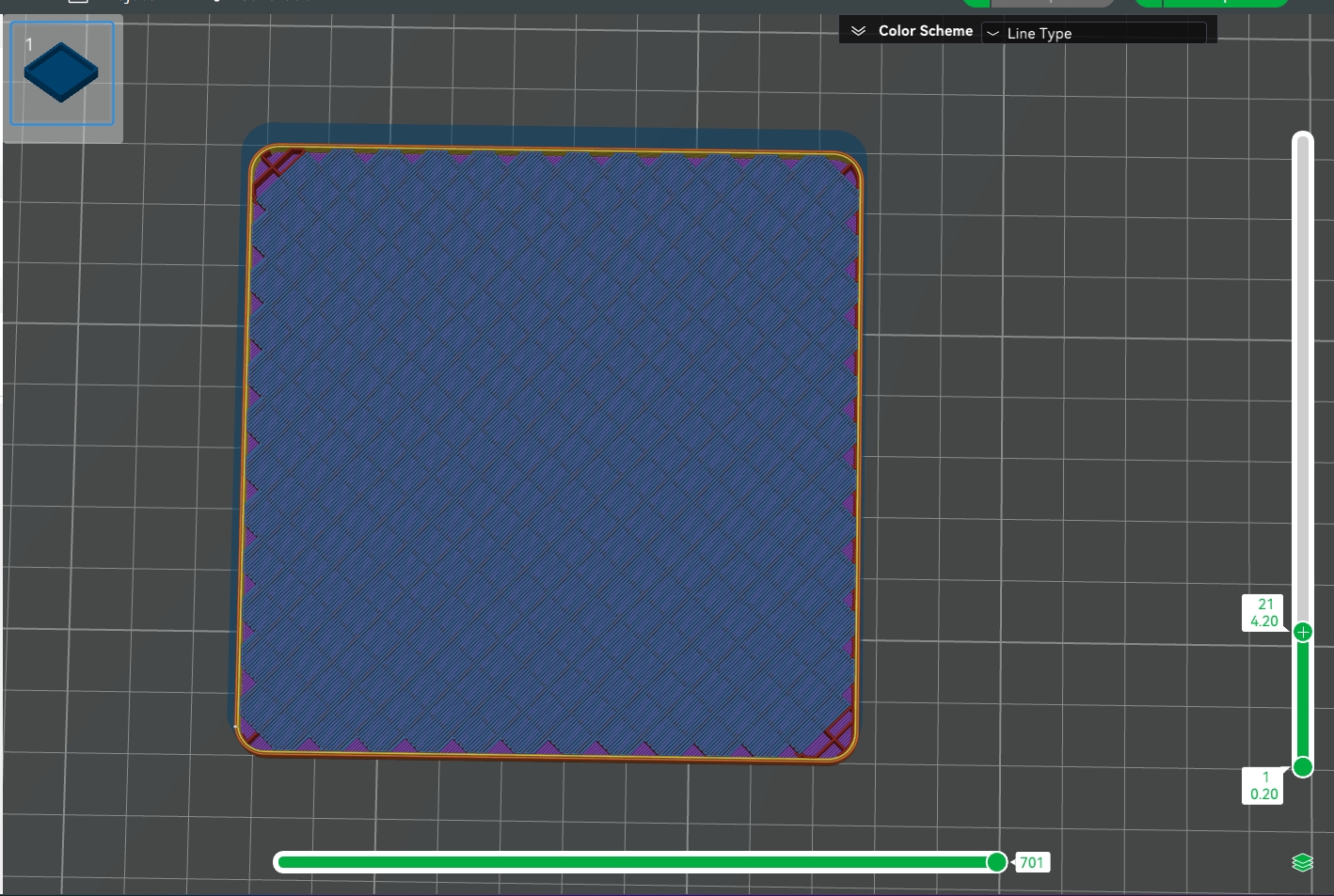
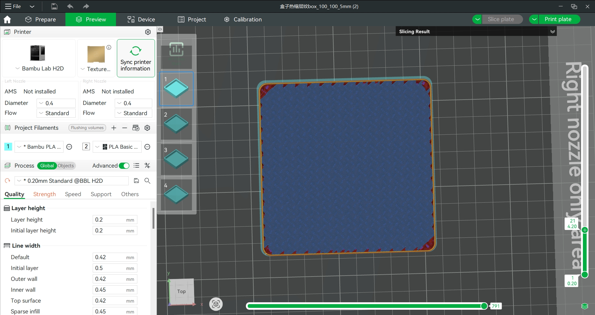
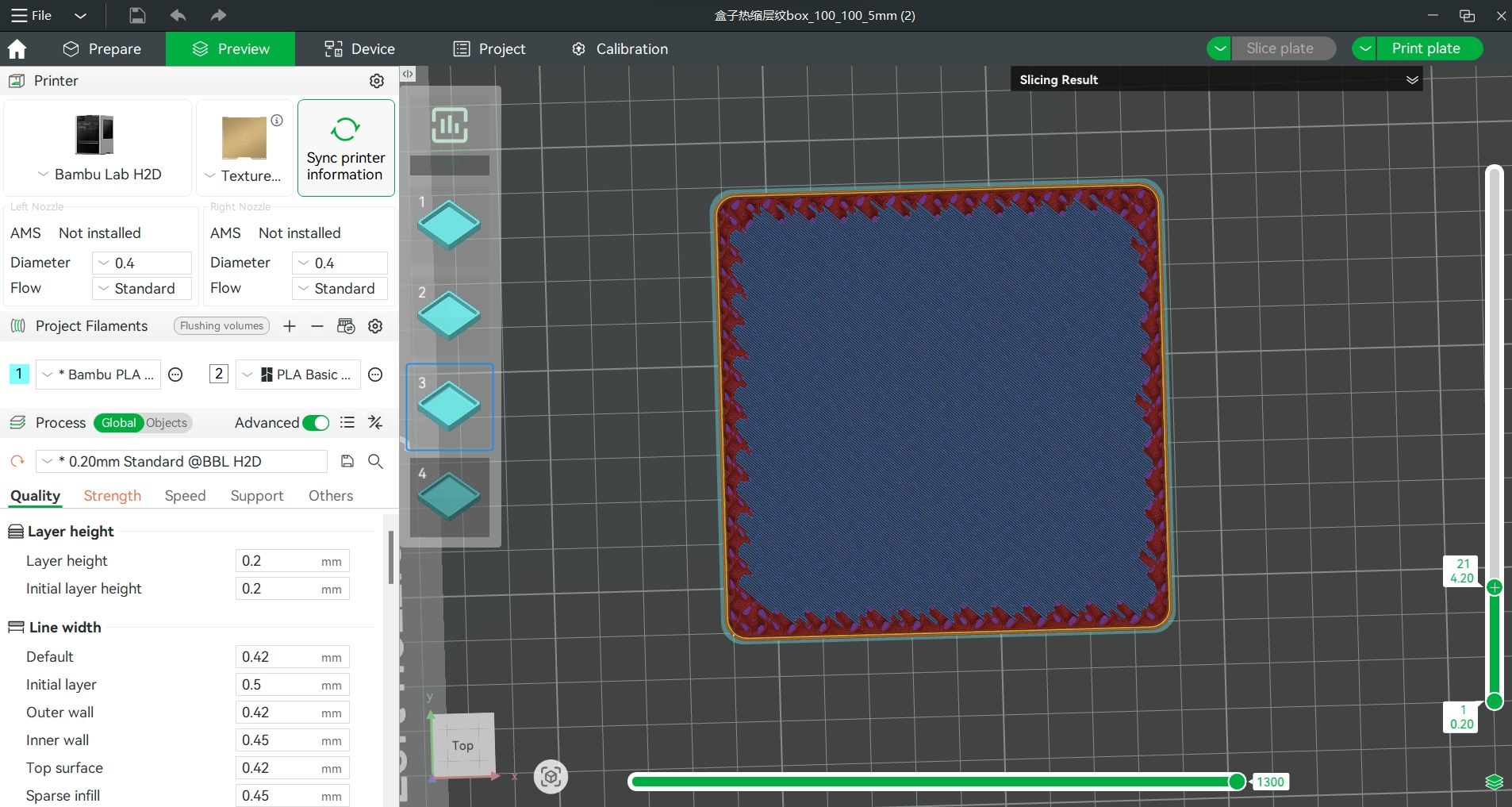
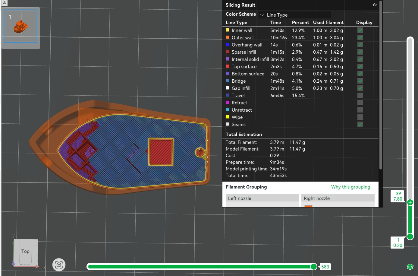
- Slicer view: The bridging layer (e.g., Layer 21 below) connects largely with the outer wall, causing increased local shrinkage stress.
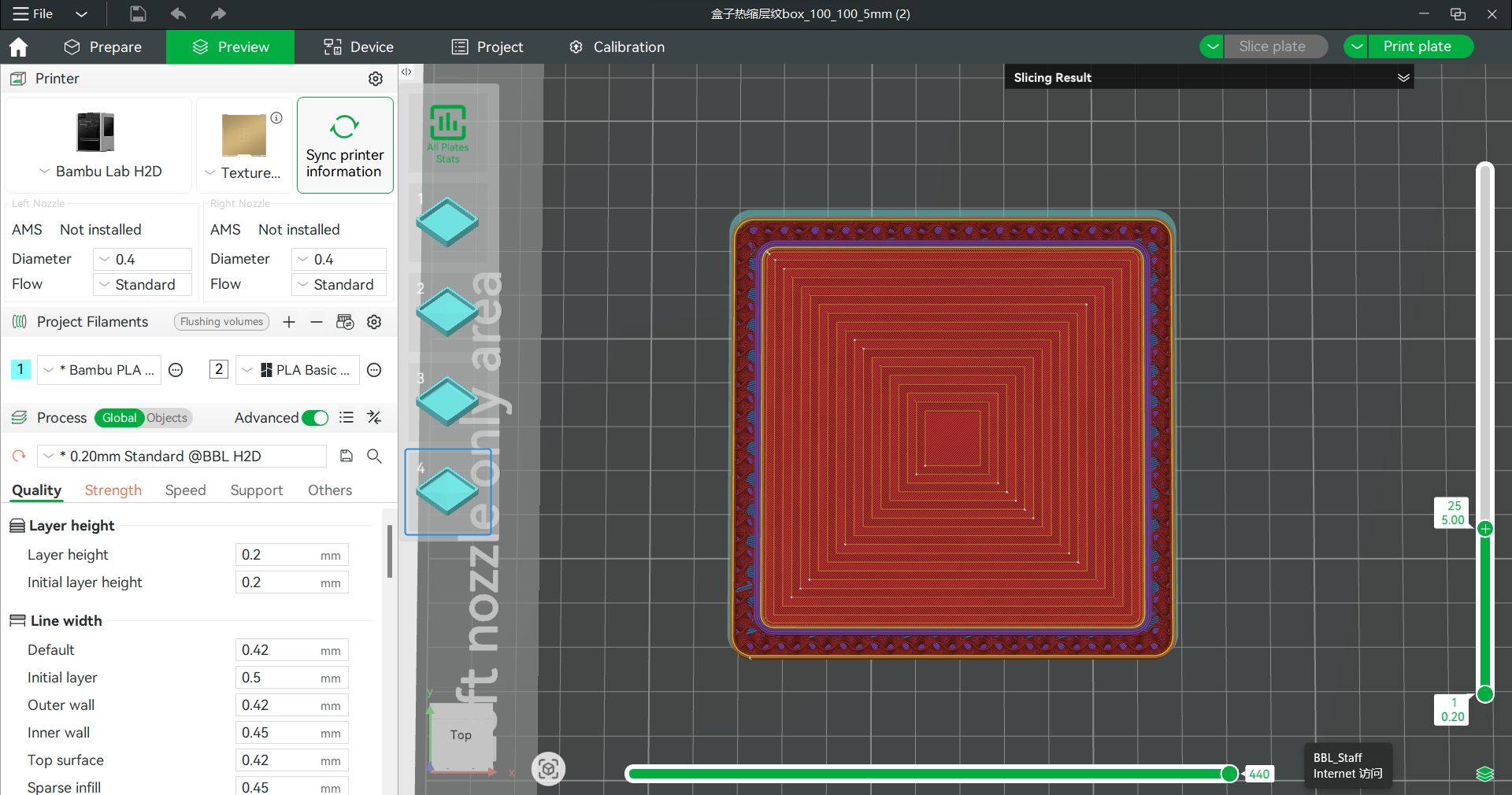
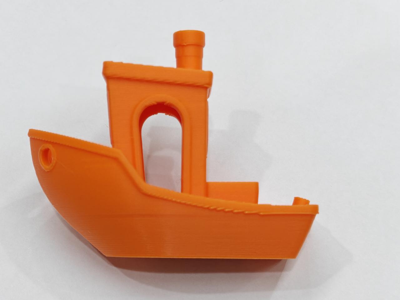
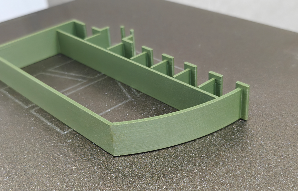
Improvement test: By modifying the model to add inner fillets or chamfers (so the bridging doesn’t touch the outer wall), the printed surface becomes much smoother, confirming bridging shrinkage stress as the main cause.
Original sliced model: bridging clearly contacts the inner wall.
- Added inner fillet: bridging no longer contacts the inner wall.
- Added inner chamfer: bridging barely touches the inner wall.
Actual print comparison:
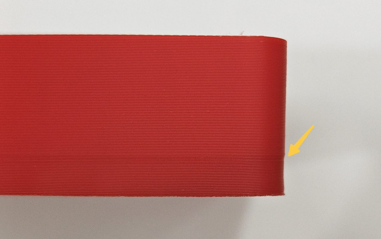 Before improvement, the outer wall showed obvious shrinkage. |
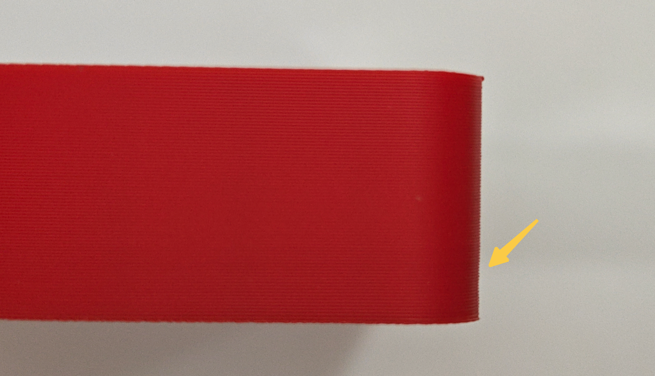 After the fix, the outer wall no longer shows obvious shrinkage. |
Case Study (3D Benchy):
- Feature: Lines appear symmetrically on both sides, only in areas contacting bridging structures.
 )
)
Slicer view: Lines appear on walls printed right after a low-speed bridge, proving shrinkage is the main cause.
 |
 |
Improvement attempts:
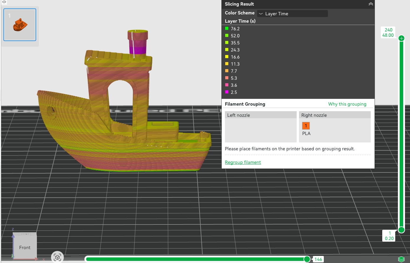
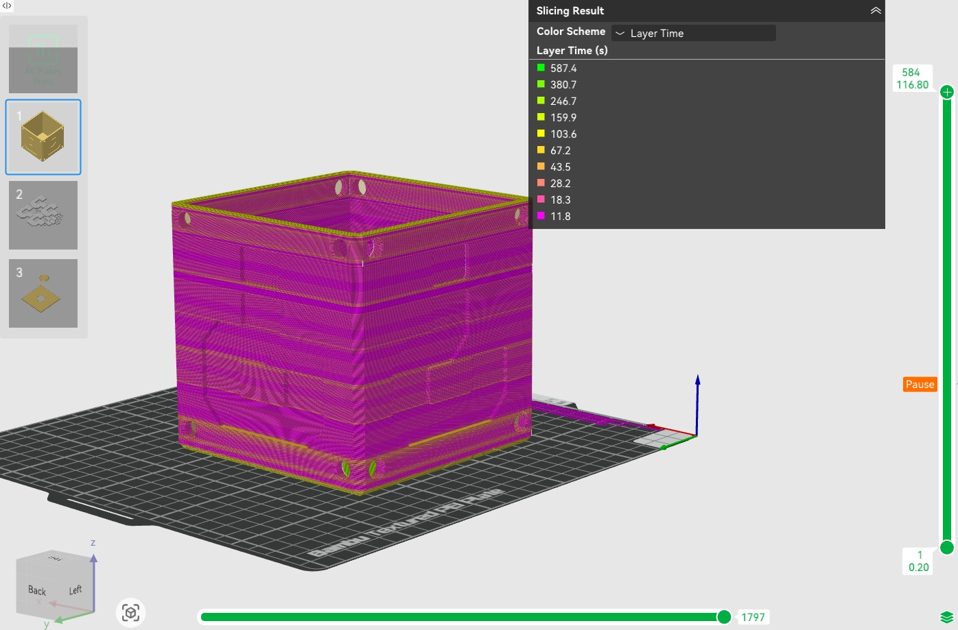
- To address the issue, we suggest adding extra parts to extend the layer time, thereby significantly increasing cooling time.
- Further improvements can be achieved by adjusting the infill pattern or reducing the fan speed to minimize shrinkage stress.
While these methods helped reduce the appearance of surface lines, they were not completely eliminated.
¶ Solutions
Based on these examples, try the following to reduce cross-section layer lines:
Model modifications (recommended first):
- Add inner fillets to stop bridging from sticking to outer walls (see box example).
Process adjustments:
- In filament settings, lower the Fan speed for overhangs to reduce bridging shrinkage.
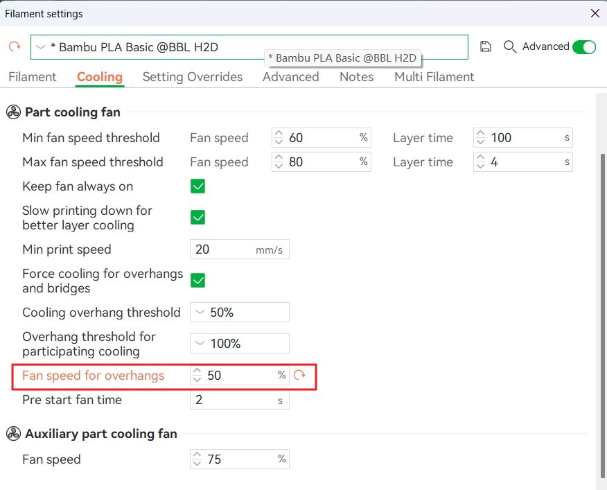
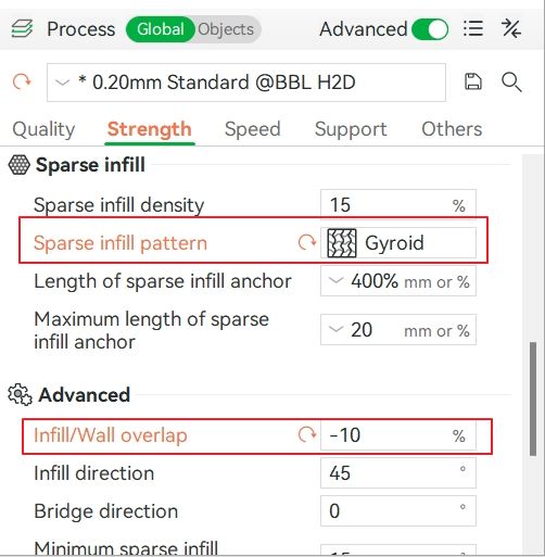
- Change Sparse infill pattern to Gyroid/Concentric and reduce Infill/Wall overlap (e.g., adjust from 15% to -10%).
- Layer time optimization:
Print multiple parts at once to increase layer time and improve cooling uniformity.
Note:
Cross-section layer lines are influenced by temperature, fan speed, geometry and more. These solutions help a lot but may not fully remove them. Combine and adjust as needed.
¶ 2. Local Warping Causing Surface Bulges
¶ Cause Analysis
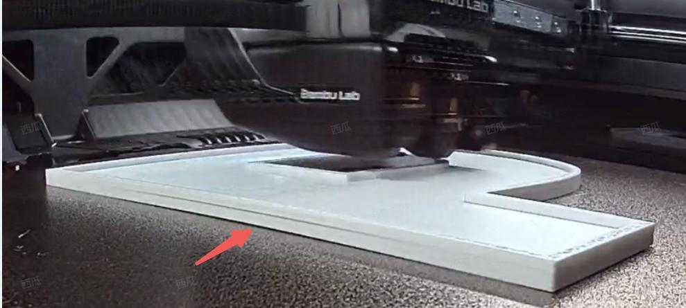
If the model base does not stick well to the build plate, local warping can happen. When a corner lifts, the nozzle-to-part gap shrinks, causing extra filament to squeeze out sideways, creating continuous bulges.
¶ Solutions
Clean the build plate: Make sure the surface is oil-free. See the Textured PEI Plate Cleaning Guide.
Add adhesion structures: Enable Brim or Brim Ears to boost bed adhesion.
Temperature control:
- Increase plate temperature slightly.
- Keep the printer front door and top cover closed (for enclosed printers) to stabilize chamber temp.
- For warp-prone materials (like ABS), use a printer with active chamber heating (e.g., H2D) and enable chamber heating to reduce shrinkage warping.
¶ 3. Flow Rate Change Layer Lines
¶ Cause Analysis
When the outer wall printing switches from a low flow rate to a high flow rate (for example, when the flow rate decreases for bridging over gaps and then increases after the bridging is completed), abnormal bulges or under-extrusion dents may occur.
Root cause: Rapid changes in flow rate can cause differences in the molten state of the material (for example, at low flow rates, material swelling may occur), leading to abnormal conditions such as material expansion.
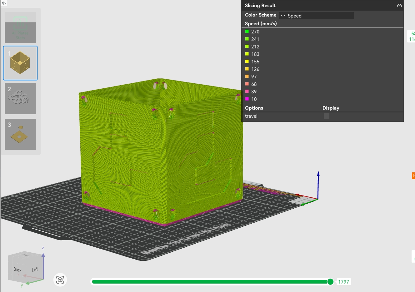
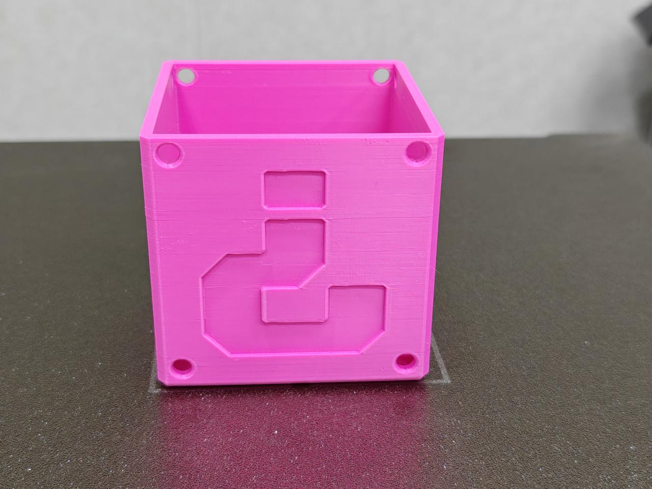
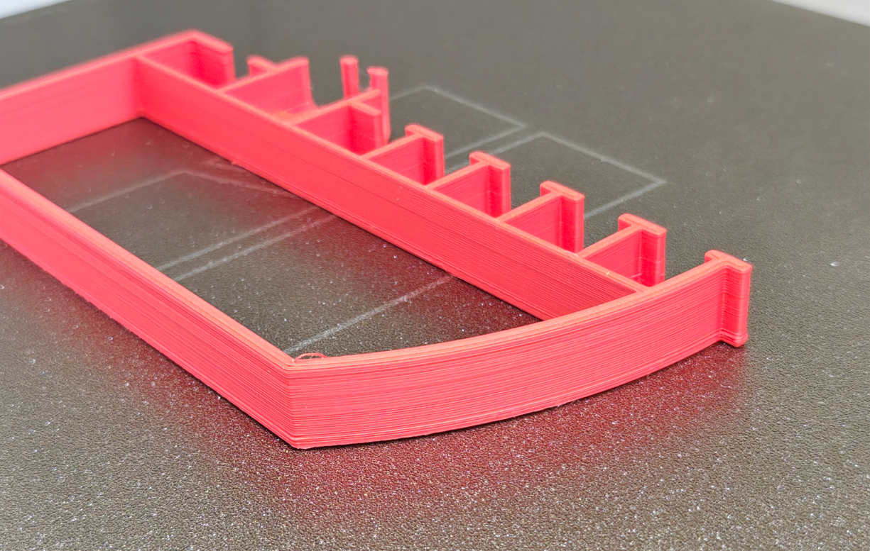
Case Study (Mario Block Box):
Models with significant layer time differences in different areas, combined with toolpaths that frequently transition between outer walls and bridging, tend to have noticeable speed (flow rate) changes. This can result in visible layer lines on the final print surface.
 |
 |
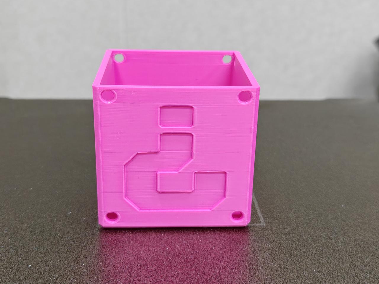
Layer lines are clearly visible:
¶ Solutions
-
Enable Flow Dynamics Calibration: Run Flow Dynamics Calibration to help the extruder adapt better to flow changes.
-
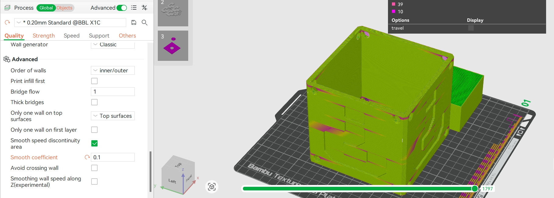
Smooth speed transitions: Lower outer wall speed and acceleration. In Bambu Studio, go to Process → Quality, enable Smooth Speed for Discontinuity Area, and reduce the smooth coefficient (e.g., 0.1 makes the transition longer and smoother). See Quality Advanced Settings.
- Conservative approach: To minimize layer lines, lower the outer wall speed to match the bridging speed. This increases print time but keeps the flow transition smooth.
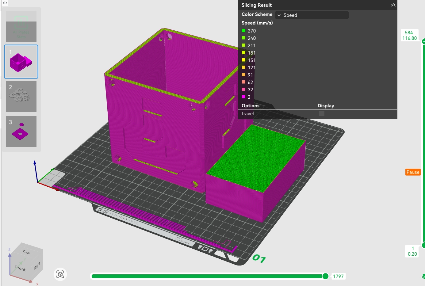
Improved result:
¶ 4. Random Irregular Layer Lines
If your surface shows random, irregular lines that don’t match the above cases (no obvious layer time or flow changes), check these possible causes:
¶ 4.1 Loose Hotend
A loose nozzle often causes random layer lines. Here's a recommendation approach to check for A1, H2D, or X/P series printers:
¶ H2 & A1 Series
Layer lines are a common quality issue in 3D printing, usually caused by a loose or improperly installed nozzle assembly. Detailed troubleshooting steps are listed below:
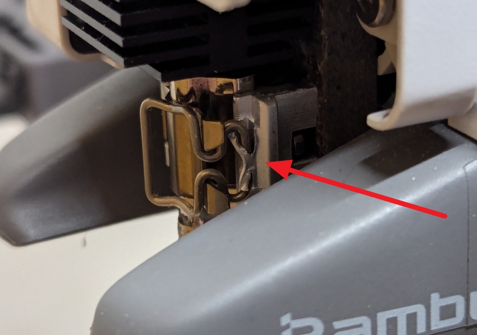
- Check the installation of the hotend clip
Remove the silicone sock from the nozzle assembly and carefully check whether the hotend clip is properly fastened.
Note: If the clip is not installed correctly, the nozzle may shift slightly during printing, which can cause layer lines.
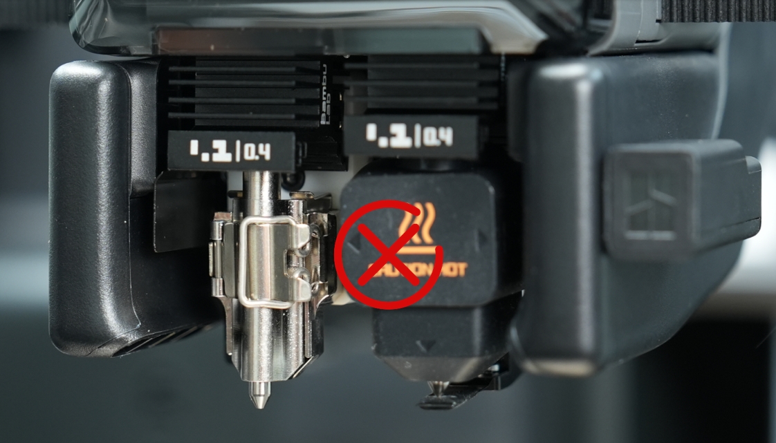 Incorrect clip |
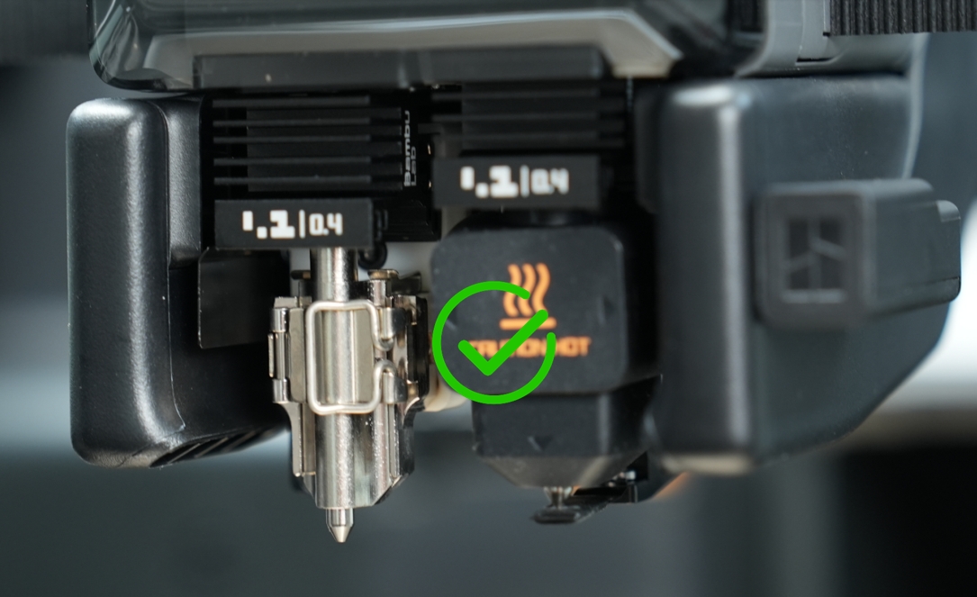 Correct clip |
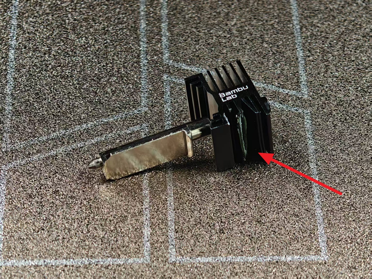
Check clip condition
Inspect the clip for bending, cracks, or wear. A bent clip may not hold securely.
Check magnet
Make sure the magnet is intact and secure. The magnet falling off can cause the nozzle assembly to not fit tightly onto the toolhead.
Check Nozzle Assembly Stability
After completing the above inspections, gently wiggle the nozzle assembly by hand to check for any noticeable movement.
Criteria: If the nozzle wobbles noticeably, it indicates that the hotend is not fully latched and the clip needs to be reinstalled.
¶ X/P Series
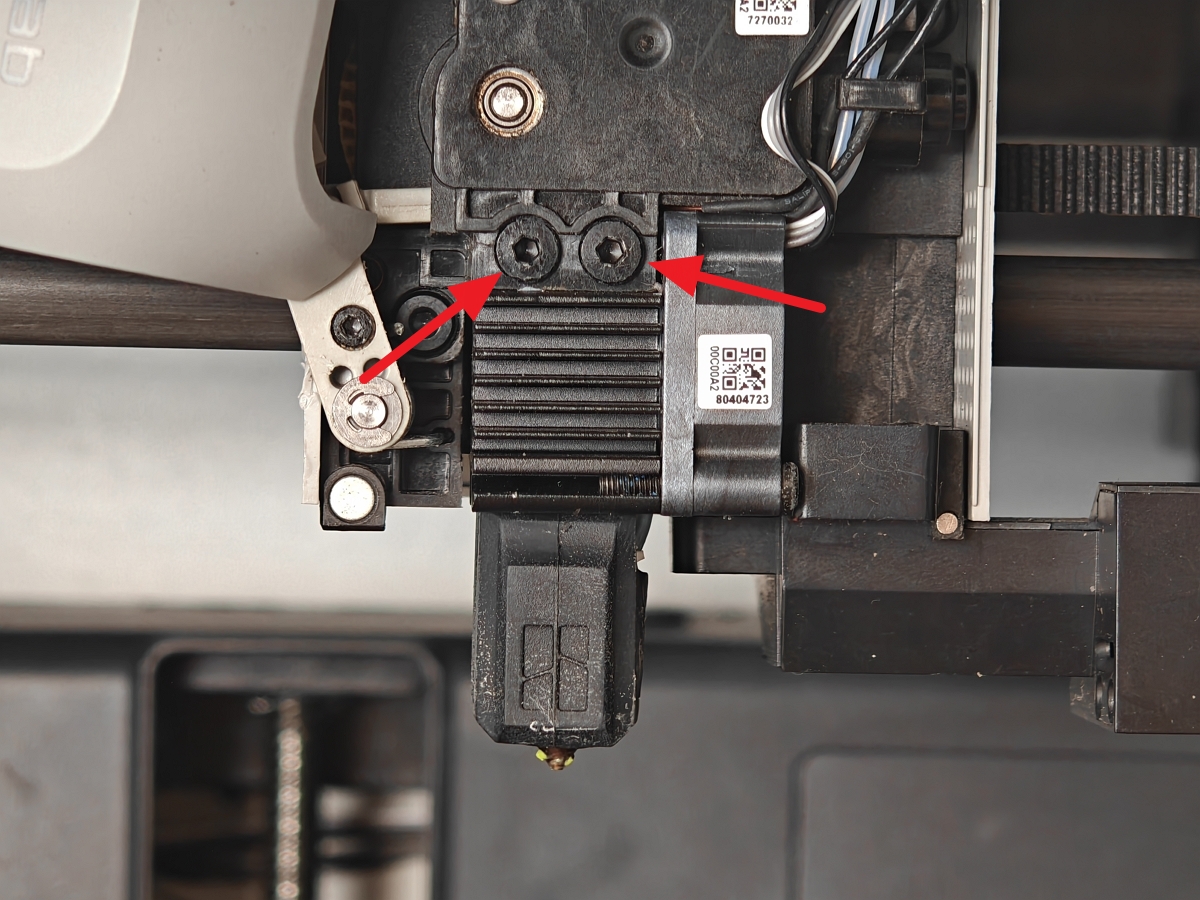
For the X/P series printers, hotend loosening issues are usually related to loosened nozzle fastening screws.
Check screws tightness:
Use an H2.0 screwdriver to verify that the fastening screws on the nozzle assembly are fully tightened.
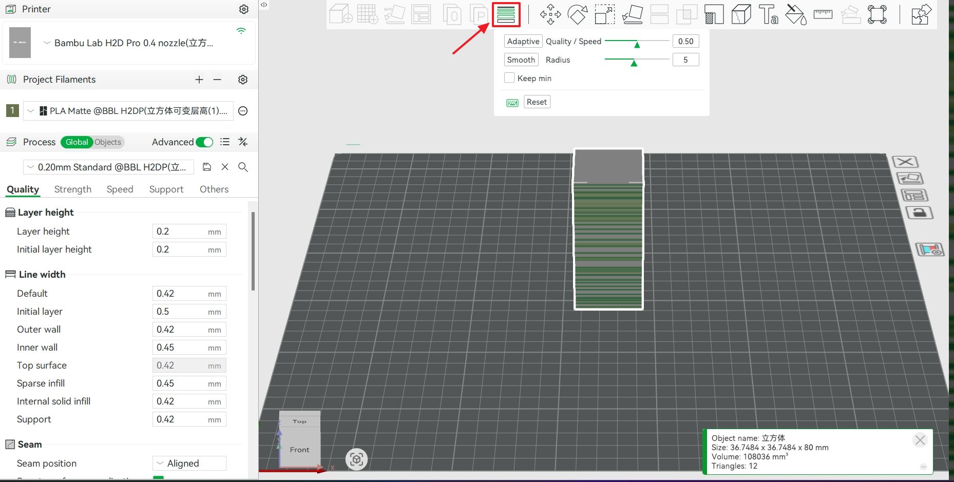
¶ 4.2 Unsmooth transition in variable layer height
¶ Symptoms:
The model uses variable layer height, and the distribution of layer lines corresponds exactly to the layer height changes in the slicing (as shown in the image below). Significant differences in layer heights between layers result in an uneven surface.
 |
 |
¶ Solution:
We recommend enabling the Smooth Mode when setting variable layer height in Bambu Studio to ensure a gradual transition between different layer heights. For more details about the variable layer height feature, please refer to the wiki. See Adaptive Layer Height.
¶ 4.3 Filament Quality
¶ Symptoms
- Random lines with uneven extrusion (local over/under extrusion)
- Extruder overload or Air printing detection
 Normal filament |
 Problem filament |
¶ Solution
- Try a different filament with consistent diameter (official Bambu filament recommended).
- Check filament diameter tolerance (should be 1.75 ± 0.02 mm).
Note:
If the above methods are ineffective, we recommend performing hardware inspection and cleaning (e.g., idler pulley cleaning, Z lead screw cleaning, extruder gear check).For complex models, it is advisable to use a fixed layer height print first to minimize variability.
¶ End Notes
We hope the detailed guide provided has been helpful and informative.
If this guide does not solve your problem, please submit a support ticket. We will answer your questions and provide assistance.
If you have any suggestions or feedback on this Wiki, please leave a message in the comment area.
Thank you for your attention!