¶ Inner Lining Assembly - Right
The spare parts for the Inner Lining Upper Cover-Right include the following:
-
Inner Lining Upper Cover-Right - Pre-installed two servos and wind blocker * 1
-
BT3x8 screws * 9
-
Used to fix the Inner Lining Upper Cover-Right and Chamber Heater Unit(Inner Lining Base-Right) * 7
-
Used to fix the Inner Lining Assembly - Right and the printer * 2
-
-
ST3x8 screws - Used to fix the Inner Lining Assembly - Right and the printer * 1
-
Nano glue - Used to attach Inner Lining Upper Cover-Right and Chamber Heater Unit(Inner Lining Base-Right) * 2
The spare parts for the Chamber Heater Unit include the following:
-
Chamber Heater Unit - The heating block is pre-installed on the Inner Lining Base-Right * 1
-
BT3x8 screw - Used to fix the Inner Lining Upper Cover-Right and Chamber Heater Unit(Inner Lining Base-Right) * 7
-
Nano glue - Used to attach Inner Lining Upper Cover-Right and Chamber Heater Unit(Inner Lining Base-Right) * 2
The spare parts for the Chamber Heat Circulation Fan include the following:
-
Chamber Heat Circulation Fan * 1
-
BT4x32 screws - Used to fix the Chamber Heat Circulation Fan * 4
-
Nano glue - Used to attach Inner Lining Upper Cover-Right and Chamber Heater Unit(Inner Lining Base-Right) * 2
¶ When to Use
-
The right inner lining upper cover or base is damaged
-
The chamber heat circulation fan is damaged or abnormal noise from the fan
-
The chamber heating function is abnormal
¶ Tools and Materials Needed
-
New spare parts(Select spare parts as required)
-
H2.0 Allen Key
-
Cross screwdriver
¶ Safety Warning
IMPORTANT!
It's crucial to power off the printer before conducting any maintenance work, including work on the printer's electronics and tool head wires. Performing tasks with the printer on can result in a short circuit, leading to electronic damage and safety hazards.
During maintenance or troubleshooting, you may need to disassemble parts, including the hotend. This exposes wires and electrical components that could short circuit if they contact each other, other metal, or electronic components while the printer is still on. This can result in damage to the printer's electronics and additional issues.
Therefore, it's crucial to turn off the printer and disconnect it from the power source before conducting any maintenance. This prevents short circuits or damage to the printer's electronics, ensuring safe and effective maintenance. For any concerns or questions about following this guide, we recommend submitting a technical ticket regarding your issue and we will do our best to respond promptly and provide the assistance you need.
¶ Remove the Inner Lining Upper Cover-Right/Chamber Heater Unit/Chamber Heat Circulation Fan
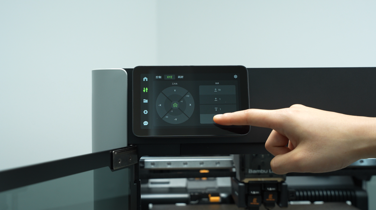
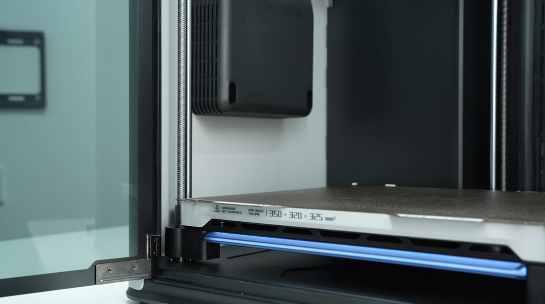
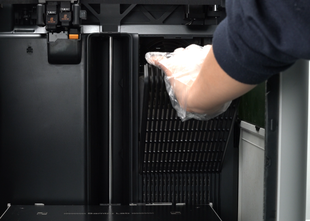
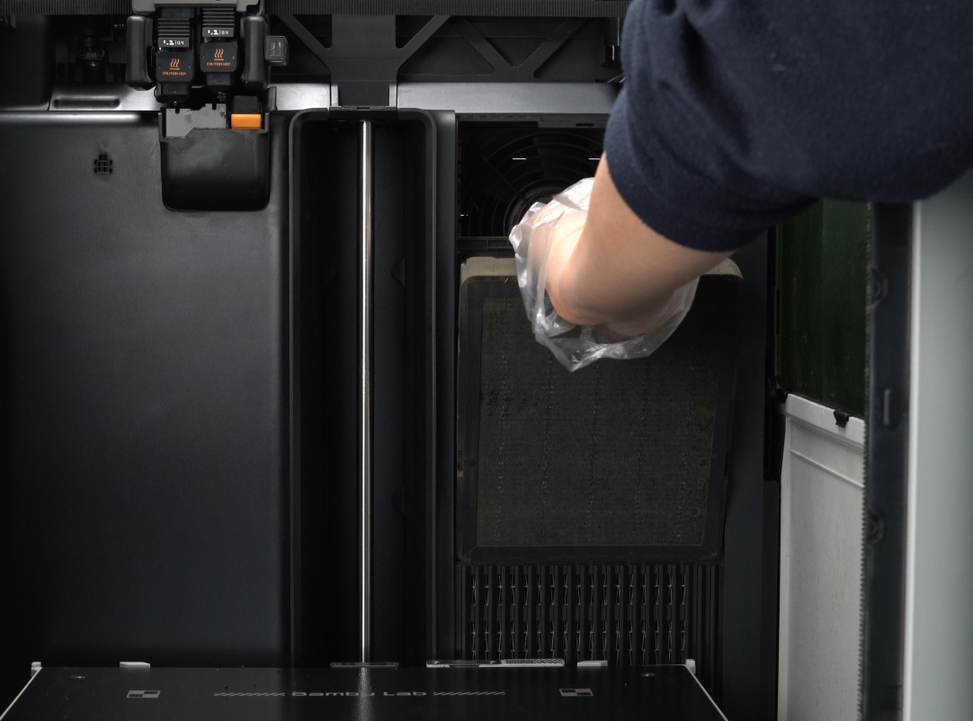
¶ Step 1:Lower heatbed and remove the activated carbon air filter
The heatbed is controlled through the screen and lowered to the bottom of the printer.
 |
 |
 |
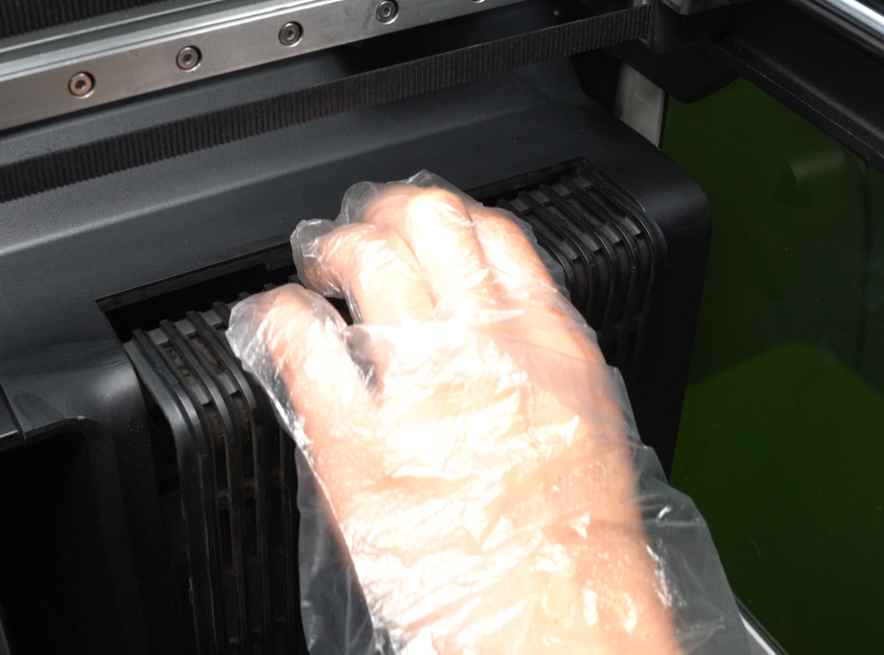
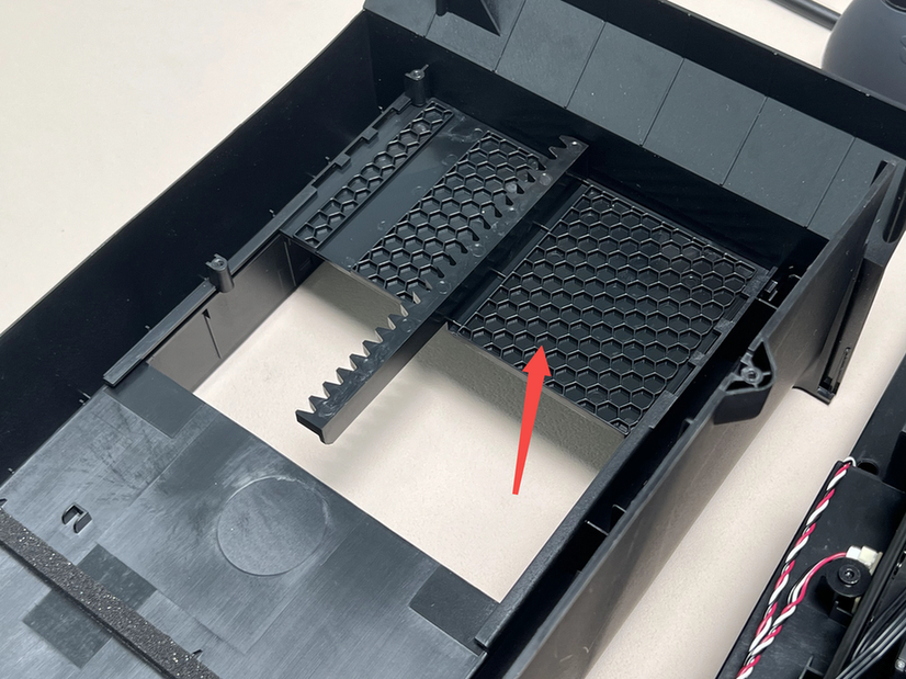
Activated carbon air filter cover and right inner lining are fastened by a buckle.You can hold the top of the activated carbon air filter cover by hand, pull it outward to unlock the top buckle, then tilt it and lift up to remove the activated carbon filter cover, and finally pull out the activated carbon filter.
If the activated carbon air filter is dirty, you can wear gloves to operate.
 |
 |
 |
¶ Step 2:Remove the Rear Panel\Purge Chute\AC Board Cover
You can refer to this Wiki to remove them in turn
-
Rear panel
-
Purge chute
-
AC Board cover
Since replacing the power switch socket does not involve the disassembly of the AC board, you can ignore the steps to replace the AC board:
Replace H2D AC Board/AC board Cover
¶ Step 3:Remove the power supply
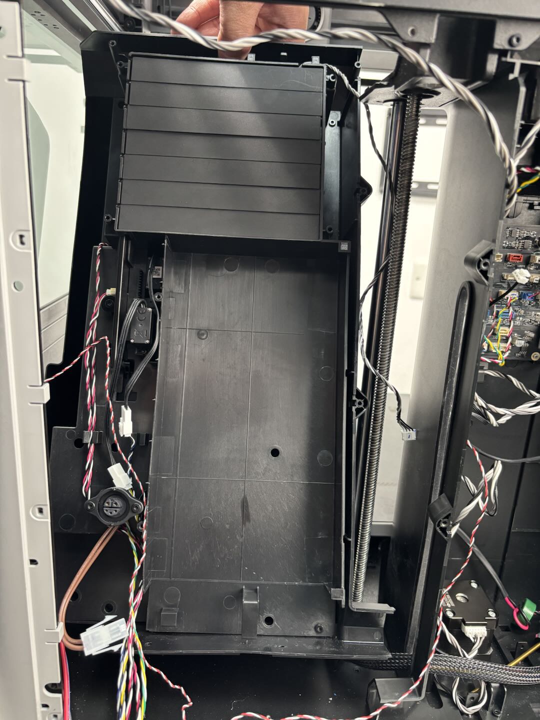
To facilitate subsequent removal of the power switch and the fixing screws on the bottom of the right inner lining, you can remove the power supply first.
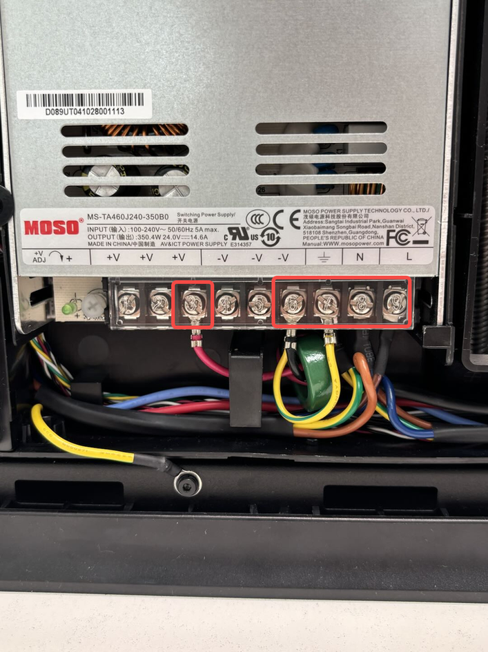
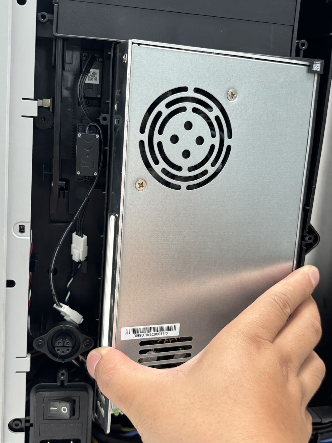
After opening the transparent protective cover upward, use a cross screwdriver to loosen the screws fixing the cables on the power supply (you do not need to completely remove them), and then take out the cables downward. Then use the H2.0 Allen Key to remove the two fixing screws (BTW3x6), then open up the printer power supply from the left side (the side where the screws are removed) and remove.
The power supply needs to be removed with a little force, and the power supply can be completely removed after the left side is removed first.
 |
 |
 |
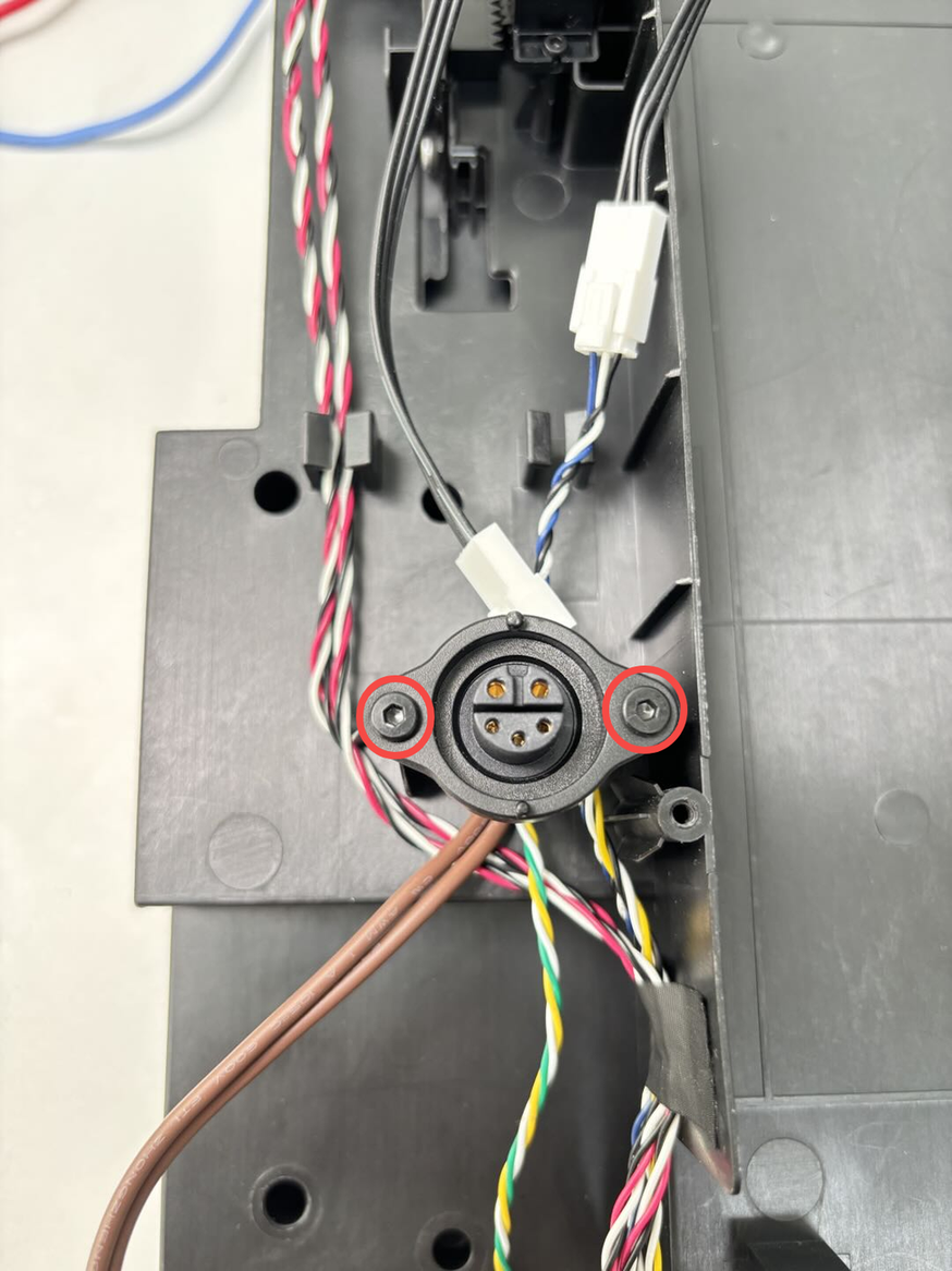
¶ Step 4:Remove the Power Socket
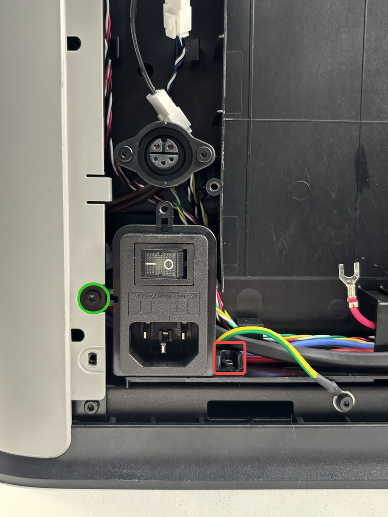
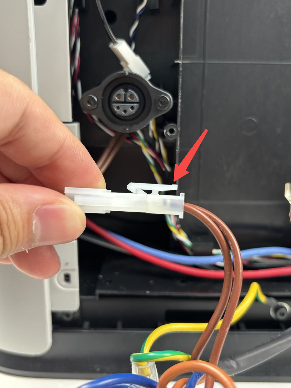
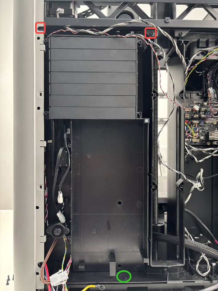
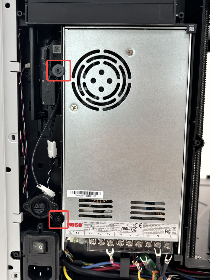
Use an H2.0 Allen key to remove the two screws (red box: ST3x8; green circle: BT3x8), pull the power switch diagonally out of the inner lining, and then press the buckle to disconnect from the power safety key base;
 |
|
¶ Step 5:Remove the cable
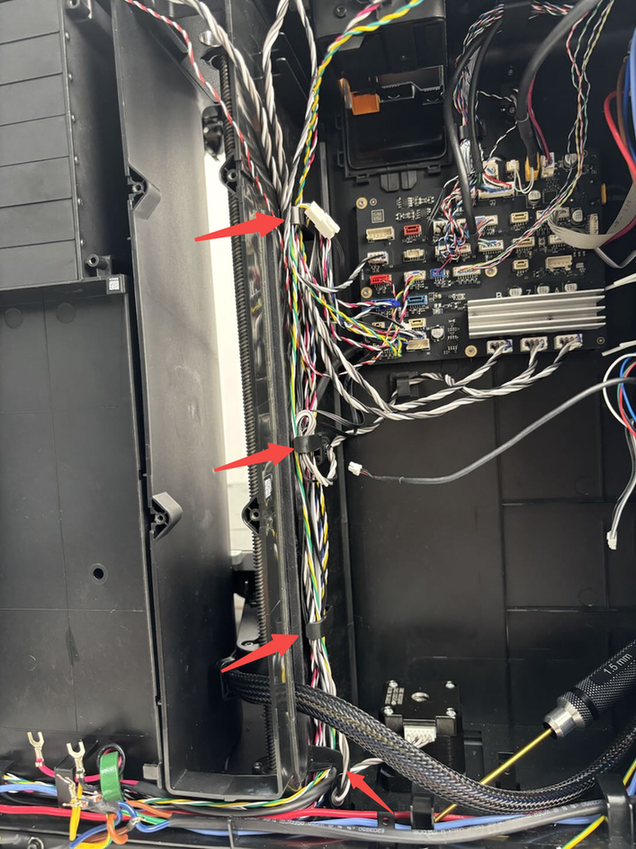
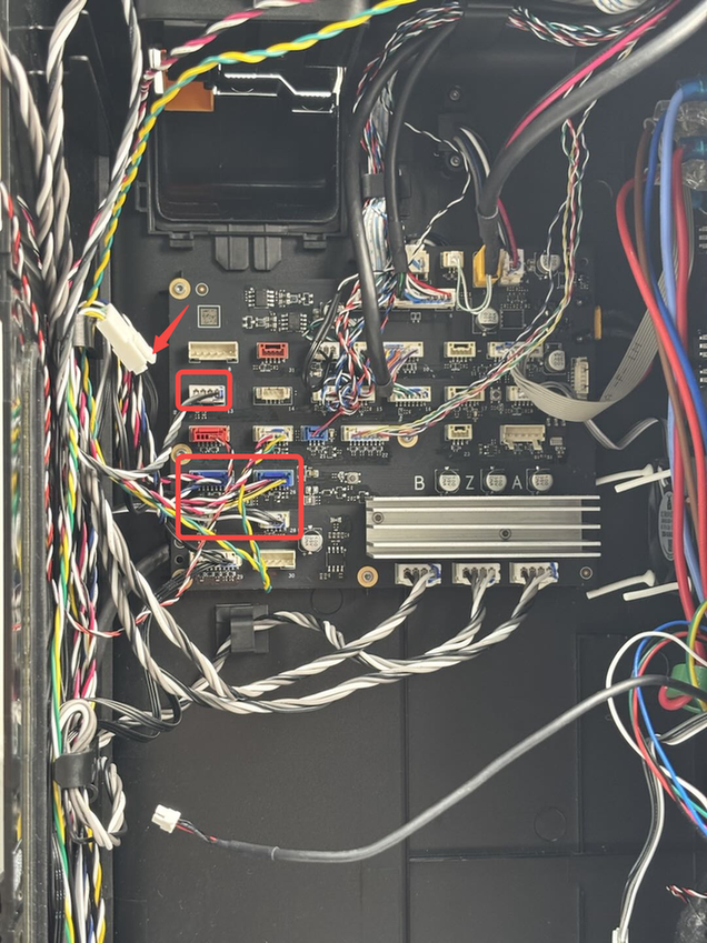
- Disconnect cables from the MC board and take them out of the cable tie on the left inner lining.
 |
|
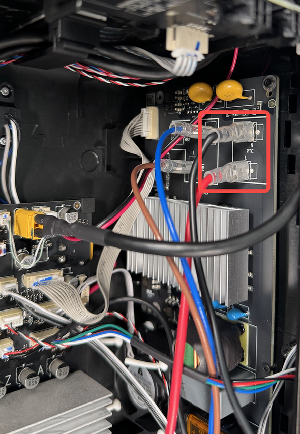
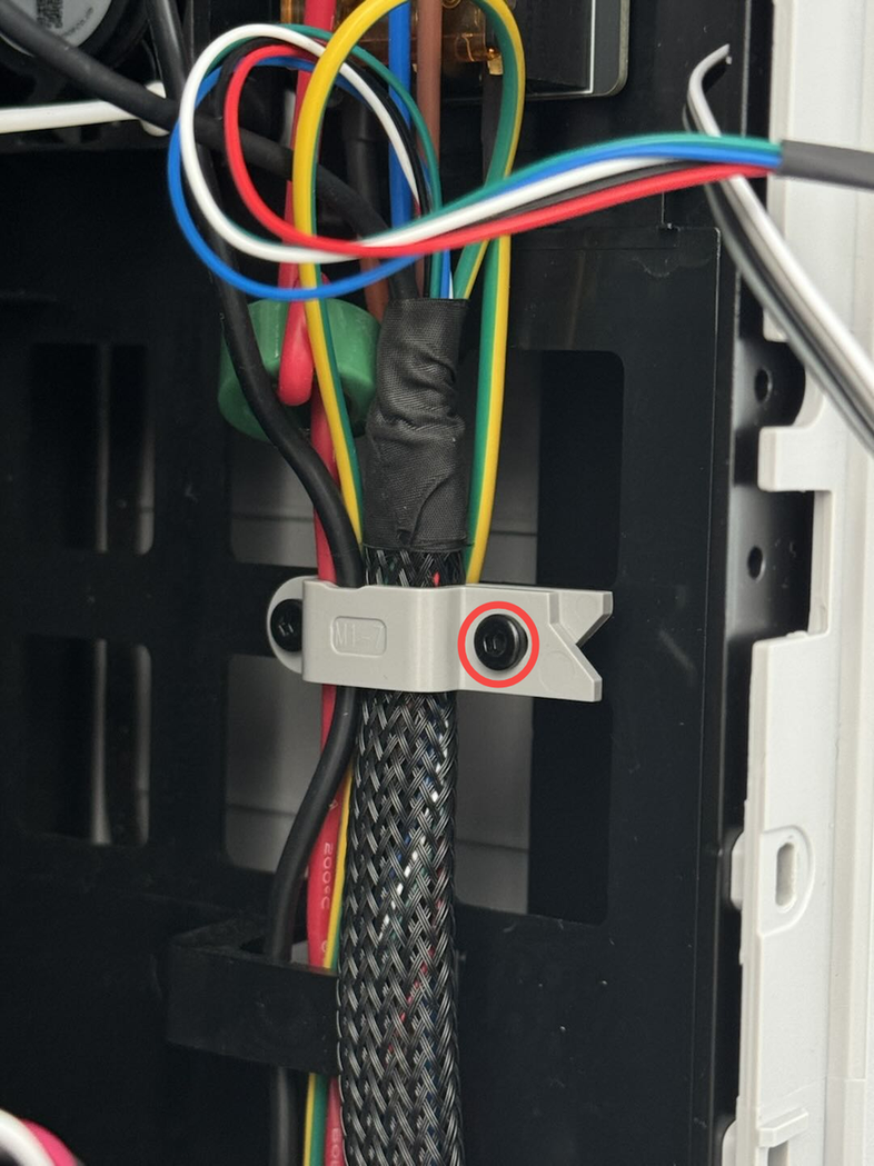
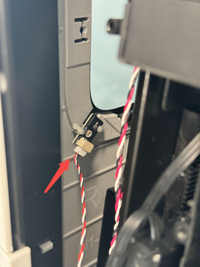
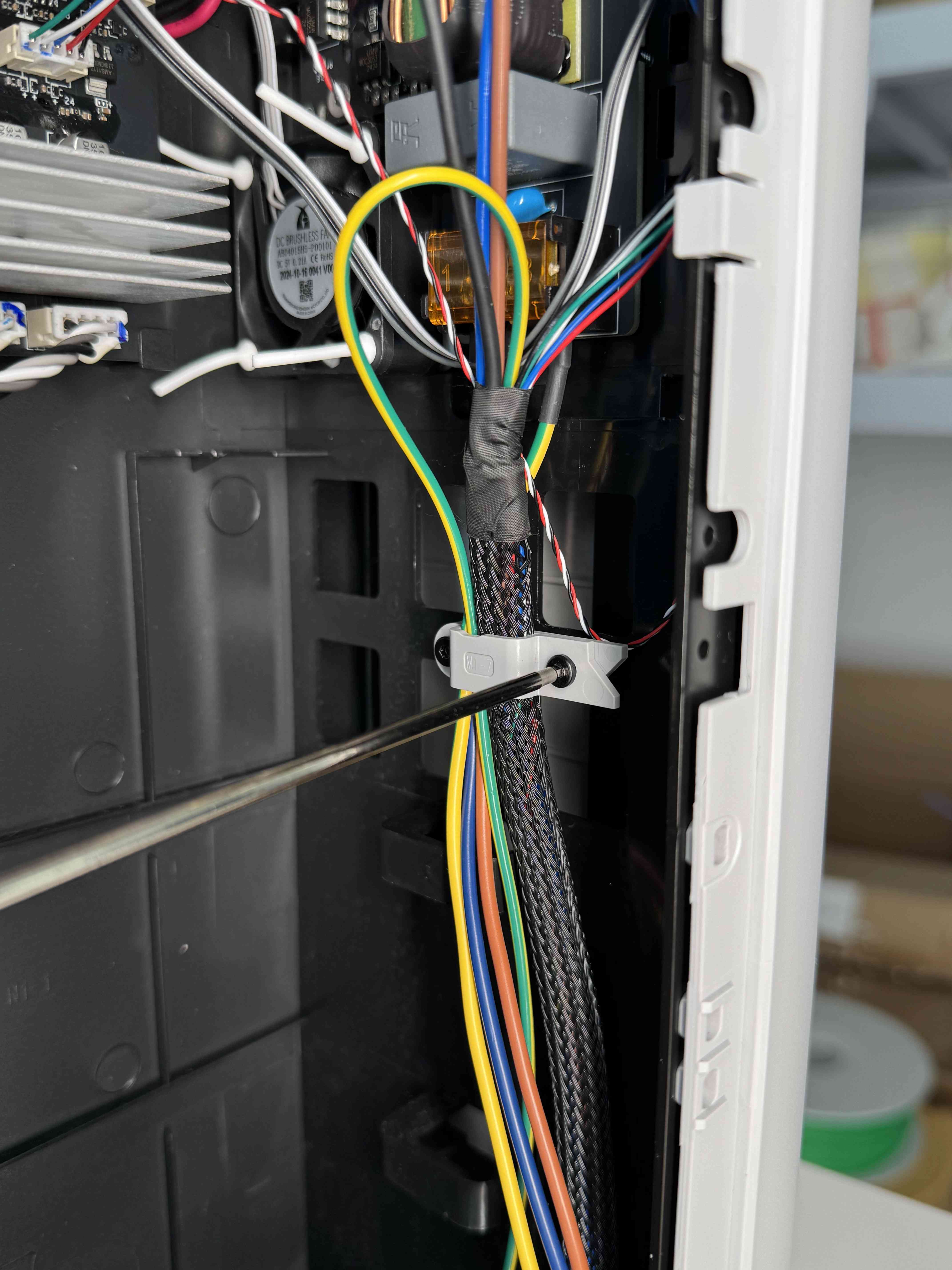
- Disconnect the power supply cable from the heating block from the AC board (push the insulation sleeve back and press the buckle to disconnect), then use an H2.0 Allen key to unlock a buckle setting screw (BT3x12) and remove the power supply cable from the buckle.
 |
 |
 |
¶ Step 7:Remove the Right Inner Lining Unit
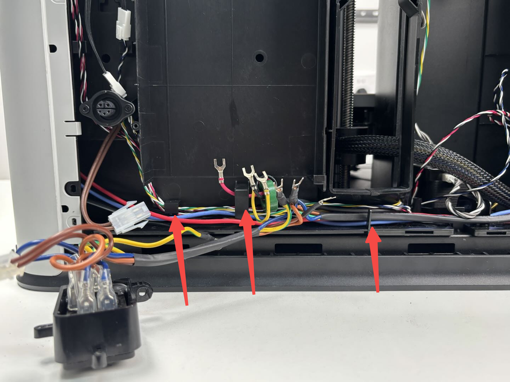
- Use an H2.0 Allen key to remove the three right inner lining setting screws (ST3x8 * 1, BT3x8 * 2) and remove the top motor wire and hall sensor cable from the cable slots.
 |
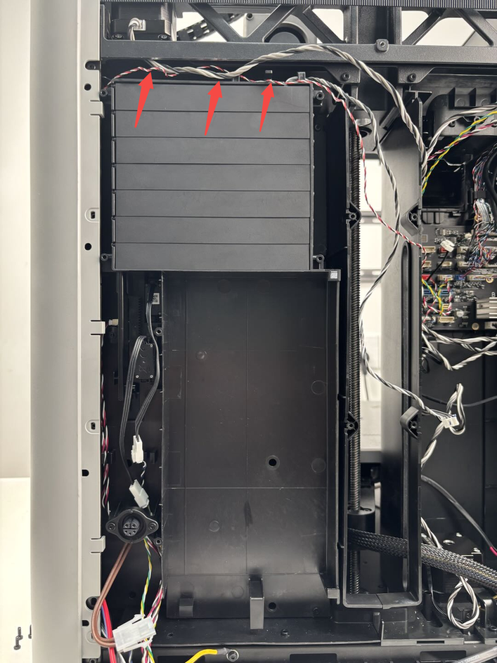 |
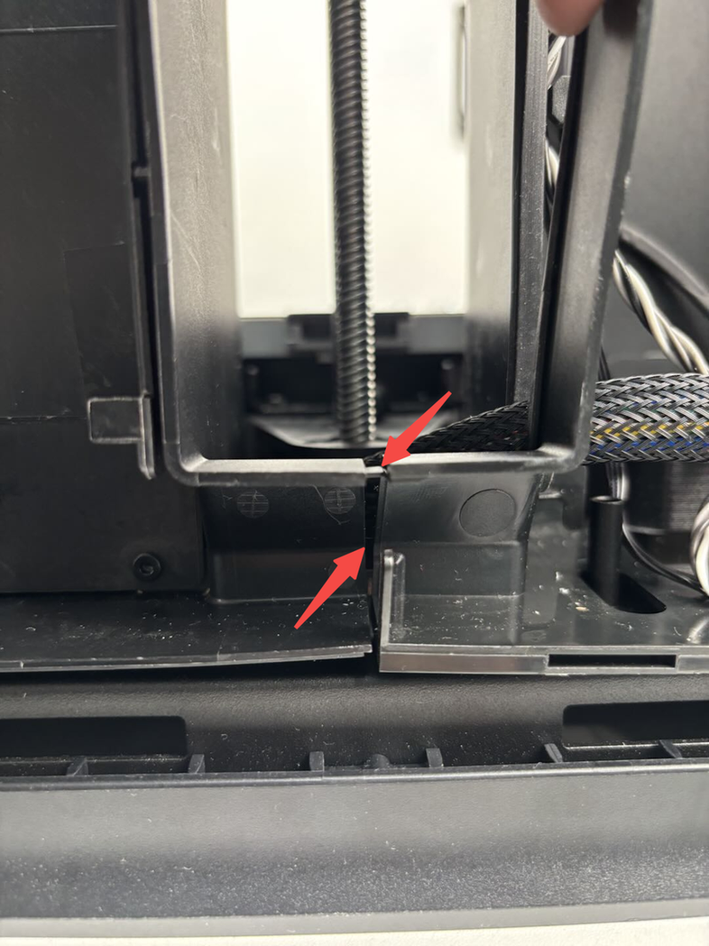
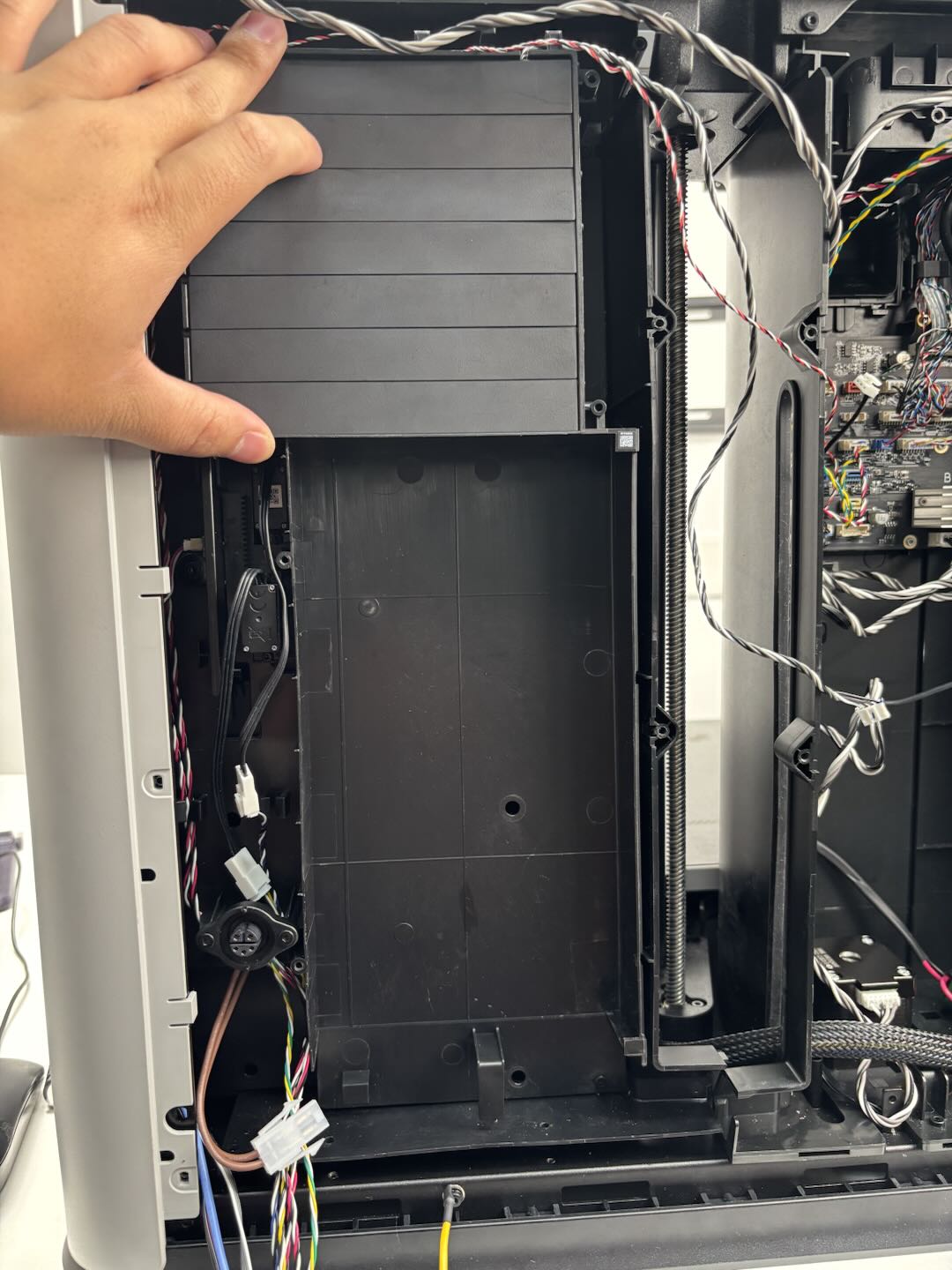
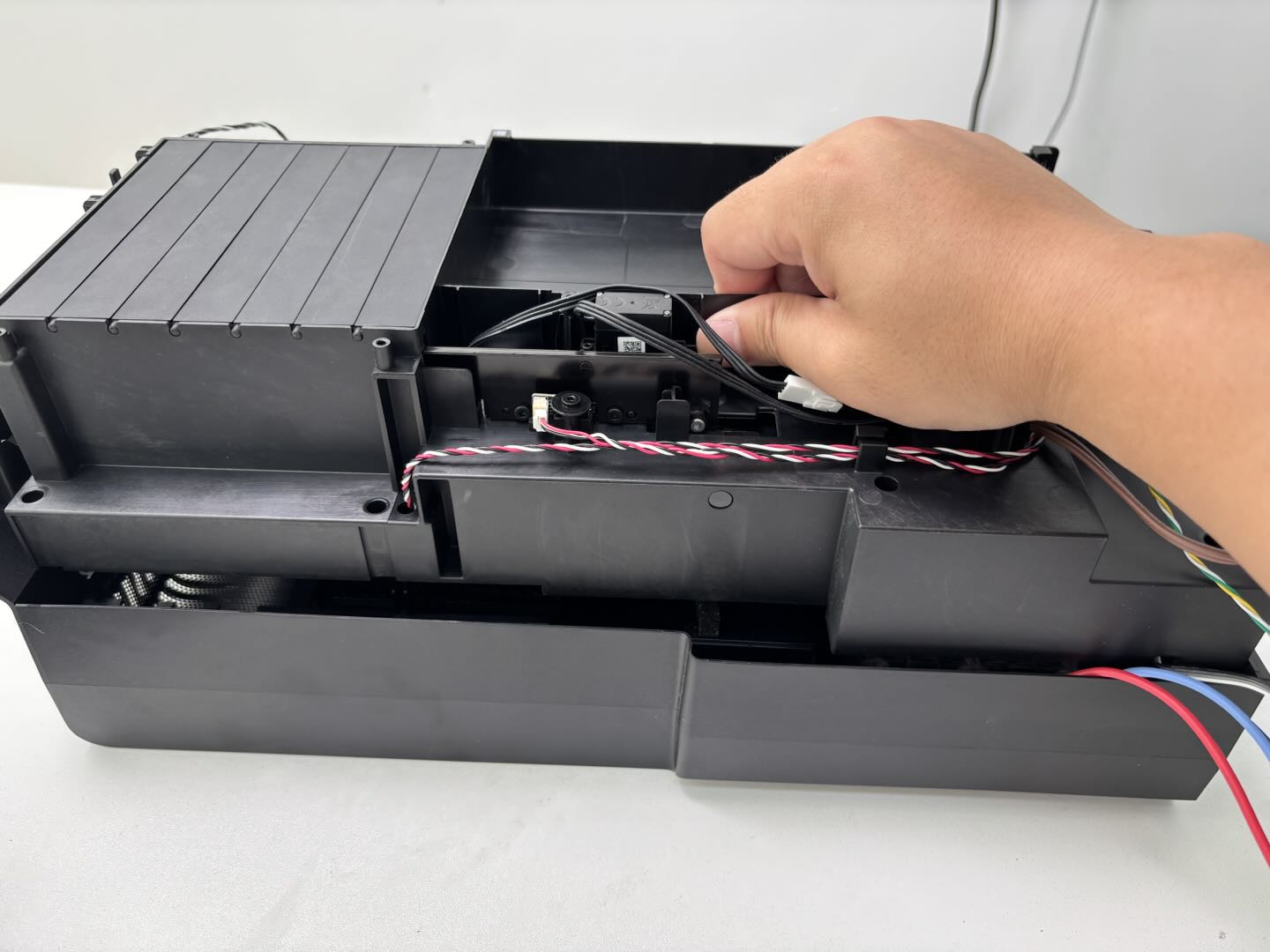
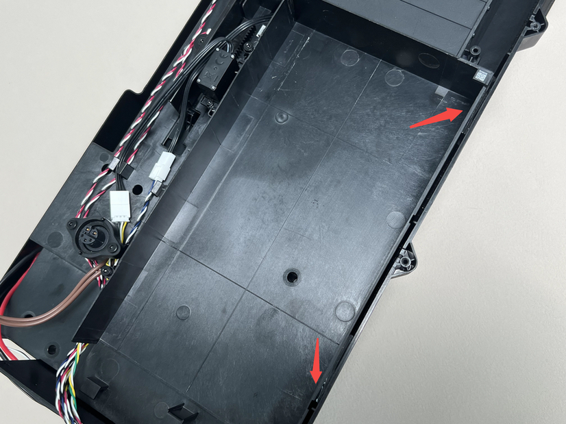
- First pull the bottom of the right lining outward and remove the two buckles, then push the right lining into the printer chamber and remove the right lining from the printer.
 |
 |
 |
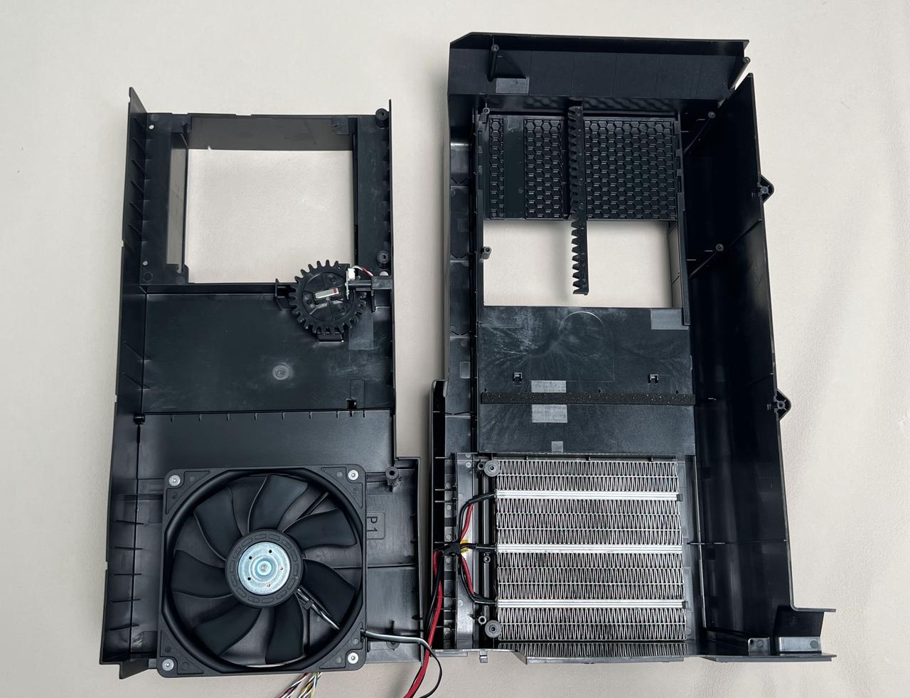
¶ Step 8:Separate the Inner Lining Upper Cover-Right/Chamber Heater Unit
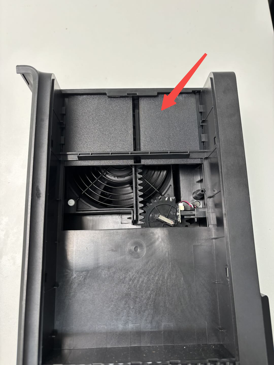
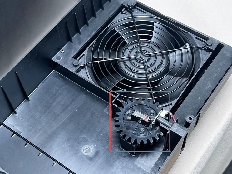
Check that the wind blocker is on top before separating Inner Lining Upper Cover-Right/Chamber Heater Unit! If it is not located at the top, first push the wind blocker to the top of the right inner lining with your hand.
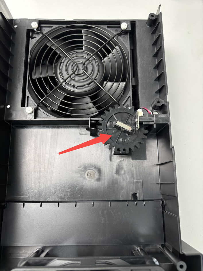
Do not turn the servo with big gear after separation!
 |
 |
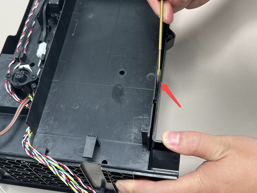
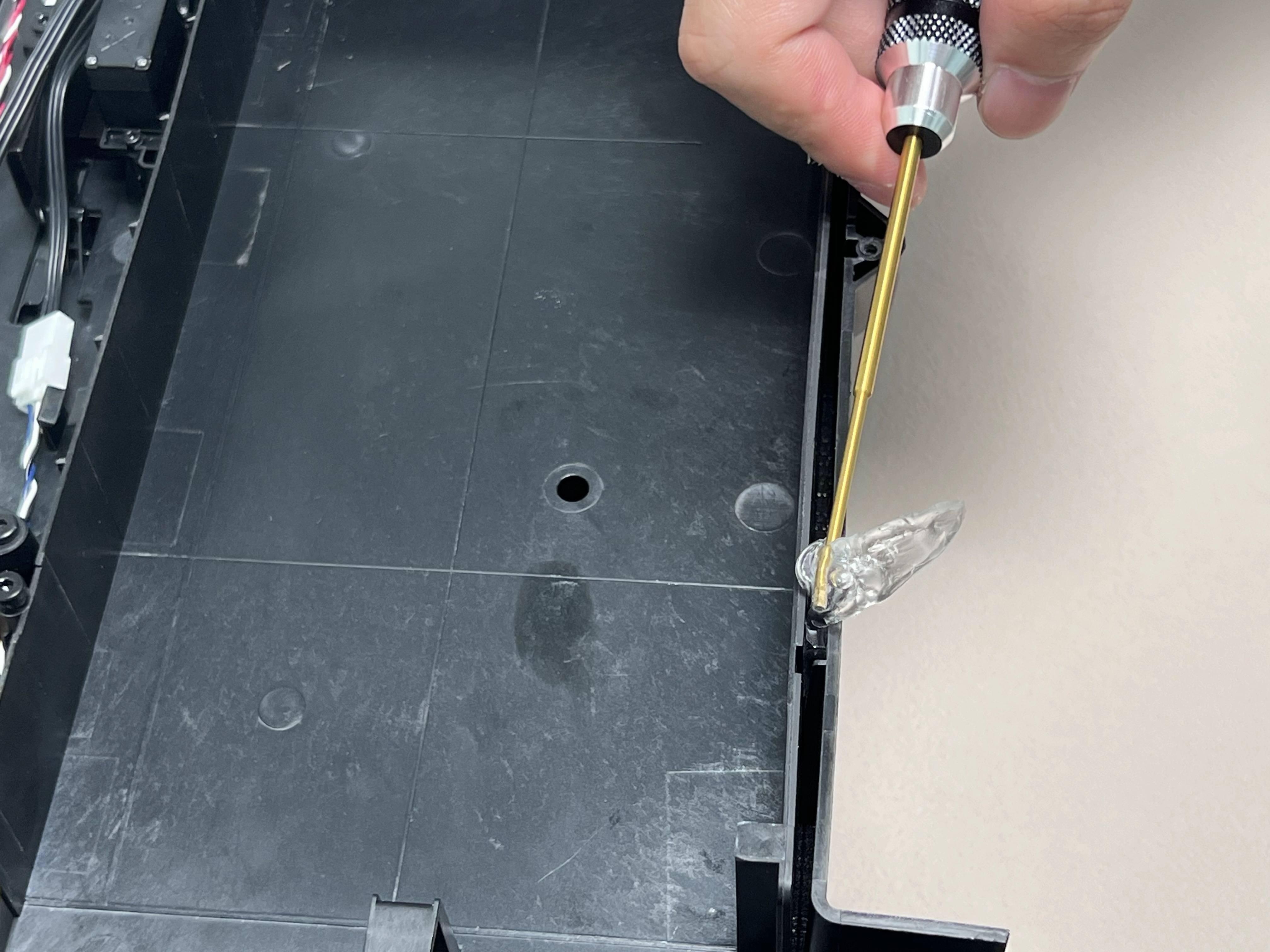
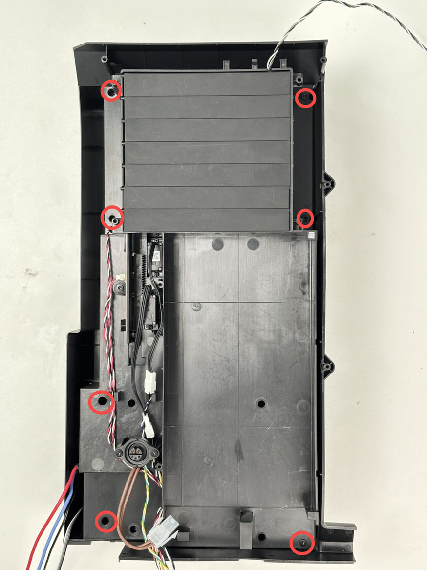
Lay the right inner lining flat, then use the H2.0 Allen key to remove 7 screws (BT3x8); Use the Allen key to pry out the nano glue attached to the right inner lining upper cover and the Chamber Heater Unit; Lift the right inner lining upper cover upward and separate it from the Chamber Heater Unit.
 |
 |
 |
 |
¶ Step 9:Select the component you want to replace
After separating Inner Lining Upper Cover-Right and Chamber Heater Unit,you can choose the replacement according to the actual situation.
Tips: Do not turn the servo in the process of replacement!
¶ Remove the Chamber Heat Circulation Fan (optional)
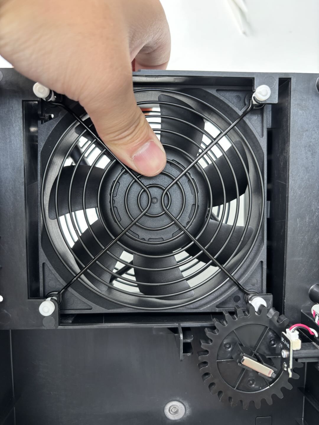
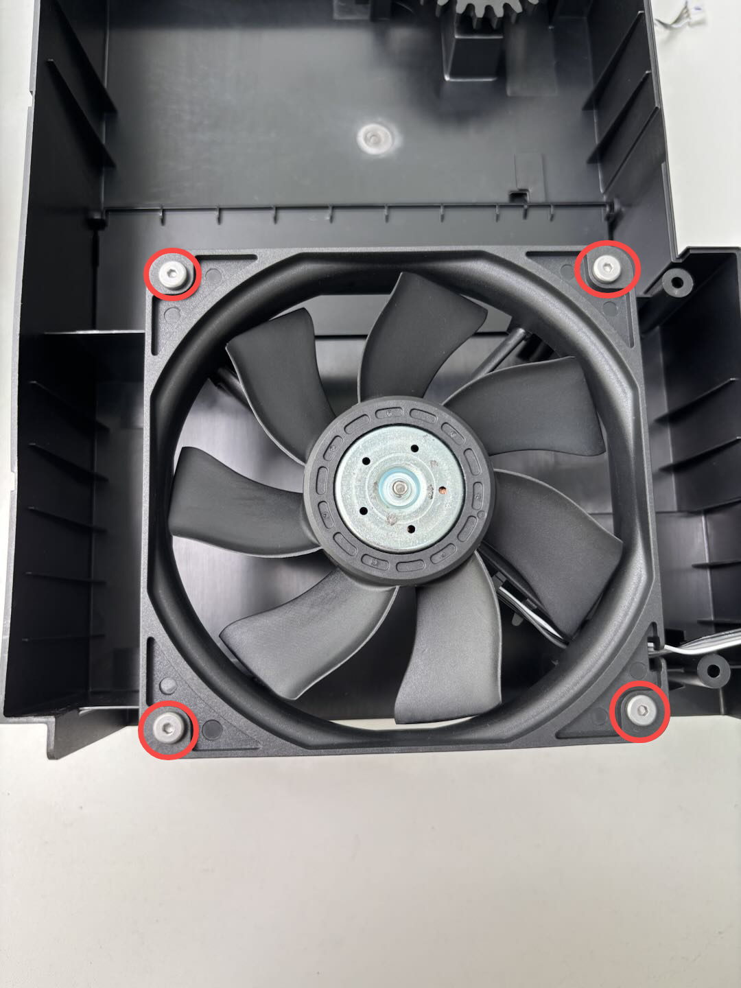
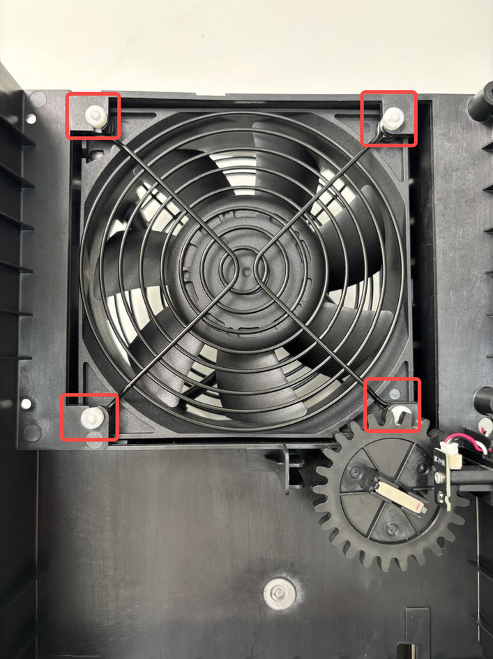
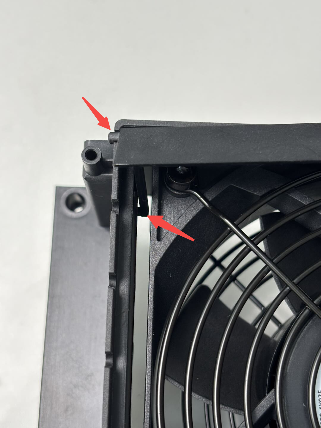
Turn the right inner lining upper cover over, then lay it flat, use the H2.0 Allen key to remove the four fixing screws (BT4x32), and remove the Chamber Heat Circulation Fan.

¶ Remove the Chamber Heater Unit (optional)
After separating Inner Lining Upper Cover-Right and Chamber Heater Unit,you do not need to remove further parts. You can directly replace the new chamber heater unit.
¶ Remove the Inner Lining Upper Cover-Right (optional)
The spare parts for Inner Lining Upper Cover-Right do not contain the following parts, you need to remove these in turn:
- Remove the Chamber Heat Circulation Fan:
Turn the right inner lining upper cover over, then lay it flat, use the H2.0 Allen key to remove the four fixing screws (BT4x32), and remove the Chamber Heat Circulation Fan.

- Remove the Power Safety Key Base:
Remove the two fixing screws using an H2.0 Allen key and remove the power safety key base.
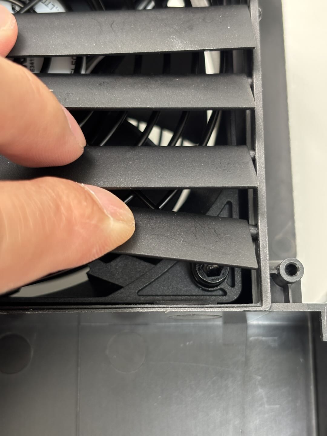
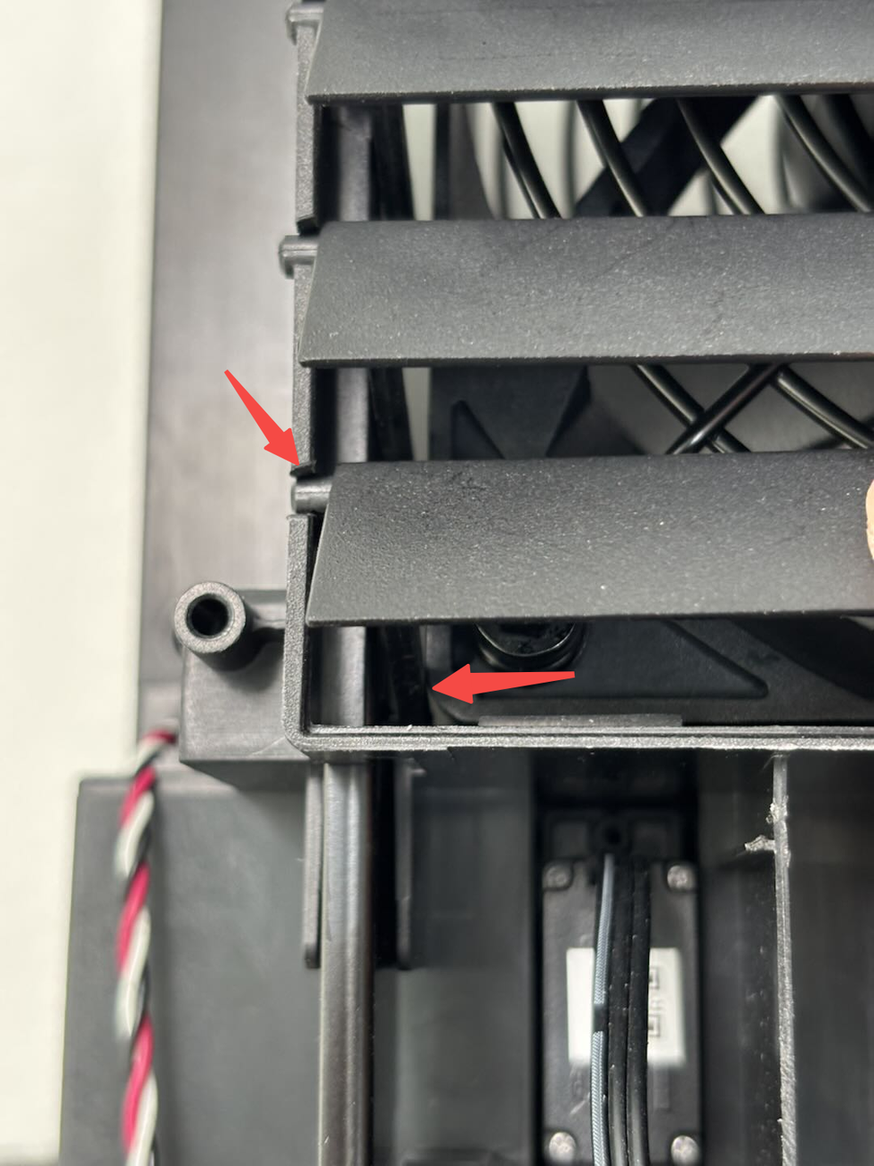
- Remove the Active Chamber Exhaust
Hold the middle of the Active Chamber Exhaust and bend it slightly, pull the right side out of the lining, and then pull out the left side of the external latch, and finally pull out the latch connected to the iron sheet to remove the active chamber exhaust. Then remove the remaining active chamber exhaust in turn.
 |
 |
- Remove the Chamber Exhaust Fan
Turn the right inner lining upper cover over and push the chamber exhaust fan outside to release the soft screws.
¶ Install the Inner Lining Upper Cover-Right/Chamber Heater Unit/Chamber Heat Circulation Fan
¶ Step 1:Select the component you want to replace
Replace based on the actual situation. If not , skip it.
¶ Install the Chamber Heat Circulation Fan (optional)
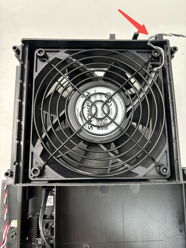
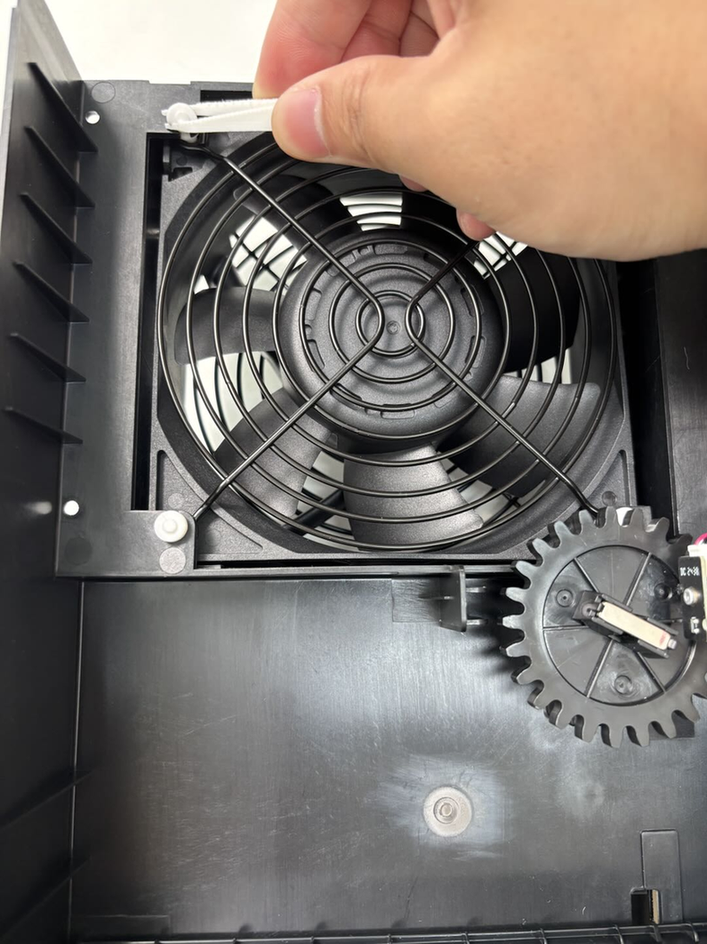
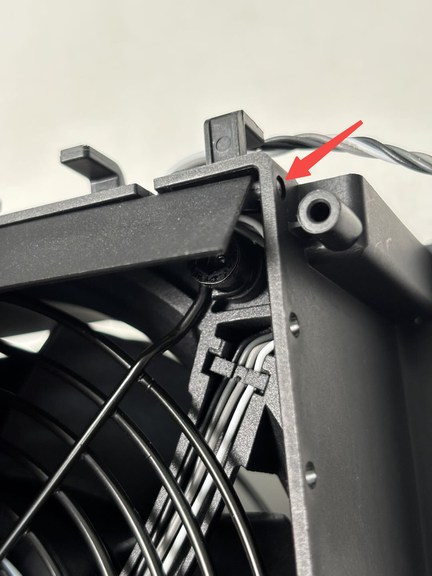
Align the Chamber Heat Circulation Fan with the screw hole on Chamber Heater Unit, and ensure that the cable is located at the lower right corner. Then use the H2.0 Allen key to tighten the four set screws (BT4x32).

¶ Install the Chamber Heater Unit (optional)
Since no additional parts need to be removed/installed due to Chamber Heater Unit, you can refer to“Step 2:Install the Inner Lining Upper Cover-Right and Chamber Heater Unit”。
¶ Install the Inner Lining Upper Cover-Right (optional)
You can install the existing parts into the new right inner lining upper cover in turn:
- Install the Chamber Heat Circulation Fan
Align the Chamber Heat Circulation Fan with the screw hole on Chamber Heater Unit, and ensure that the cable is located at the lower right corner. Then use the H2.0 Allen key to tighten the four set screws (BT4x32).
- Install the Power Safety Key Base:
Align the power safety key base with the screw hole on the right inner lining. Pay attention to the direction during installation. You can refer to the figure below to confirm the direction and then use the H2.0 Allen key to tighten the two fixing screws.

- Install the Chamber Exhaust Fan
You can install soft screws on the Active Chamber Exhaust, and ensure that the fan cable is located in the upper right corner. Turn the right inner lining upper cover over and insert four soft screws into the right inner lining upper cover one by one with the assistance of tweezers.
When installing soft screws, avoid touching the gear of servo to avoid abnormal position due to rotation.
 |
 |
 |
- Install the Active Chamber Exhaust
Insert the latch on the left side of the new exhaust grille into the iron sheet, then insert the latch on the left side of the outside into the lining, and finally hold the middle of the exhaust grille to bend it and insert the latch on the right side. Install the remaining automatic exhaust grilles in turn.
 |
 |
¶ Step 2:Install the Inner Lining Upper Cover-Right and Chamber Heater Unit
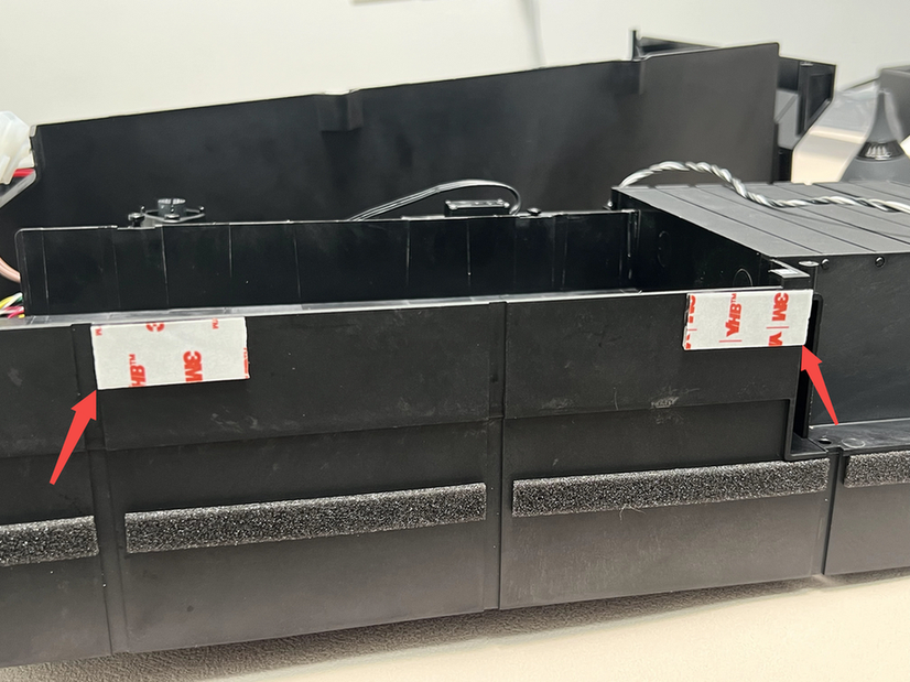
Paste the new nano glue on the outside of the right inner lining upper cover first, and then check whether the wind blocker on the Chamber Heater Unit is located on the top, and then fasten right inner lining upper cover into the Chamber Heater Unit after confirming that it is located on the top.
 |
 |
 |
Press the nano-adhesive position tightly firstly, and then use the H2.0 Allen key to tighten the 7 fixing screws (BT3x8).
 |
 |
¶ Step 3:Install the Right Inner Lining Unit
- Insert the Right Inner Lining Unit diagonally from the printer chamber, connect the bottom buckle to the left lining.
The connecting hall sensor cable of the glass on the right panel should be wound to the top, please pay attention to avoid the way.
 |
 |
 |
- Use an H2.0 Allen key to tighten the three fixing screws (ST3x8 * 1, BT3x8 * 2), and clamp the hall sensor cable on the right panel and the X/Y motor cable into the cable slot on the top of the right inner lining.
 |
 |
¶ Step 4:Connect the cable
- Insert the cables into the cable trough at the bottom of the printer, connect the cables on the right inner lining unit to the MC board, and tie the cables into the cable tie.
 |
 |
 |
- Connect the power supply cable of the heating block to the AC board, tie the cable into the cable tie, and use the H2.0 Allen key to tighten a cable tie fixing screw (BT3x12).
 |
|
¶ Step 5:Install the Purge Chute and AC Board Cover
Refer to this wiki: Replace H2D AC Board/AC board Cover Install the Purge Chute and AC Board Cover.
¶ Step 6:Install the Power Socket
Connect the power socket to the power safety key switch socket cable, then clamp the left side of the power switch into the printer, then push the switch into place, use the H2.0 Allen key to tighten the two fixing screws (BT3x8, ST3x8)
 |

|
¶ Step 7:Install the power supply
Put the right side of the power supply into the inner lining first, then push the left side of the power supply into the inner lining, and use the H2.0 Allen key to tighten the two screws (BT3x6). Open the transparent protective case and tighten the fastening screws on the power cable using a cross screwdriver.
 |
|
¶ Step 8:Install the Rear Panel
You can refer to the following Wiki to install the printer rear panel.
¶ Verify the functionality
¶ Filter Switch Flap Servomotor Verification
Power on the printer, access the control interface, select Air Condition System, then set Cooling Mode to Heating. Correct installation is confirmed when observing normal upward/downward movement of the filter switch flap.

If the flap fails to move properly, refer to Steps 7 and 8 to verify:
- The flap was at its highest position during installation
- The magnet remains horizontal with its red-marked end facing the hall sensor
¶ Chamber Exhaust Servomotor Verification
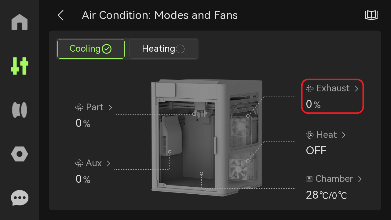
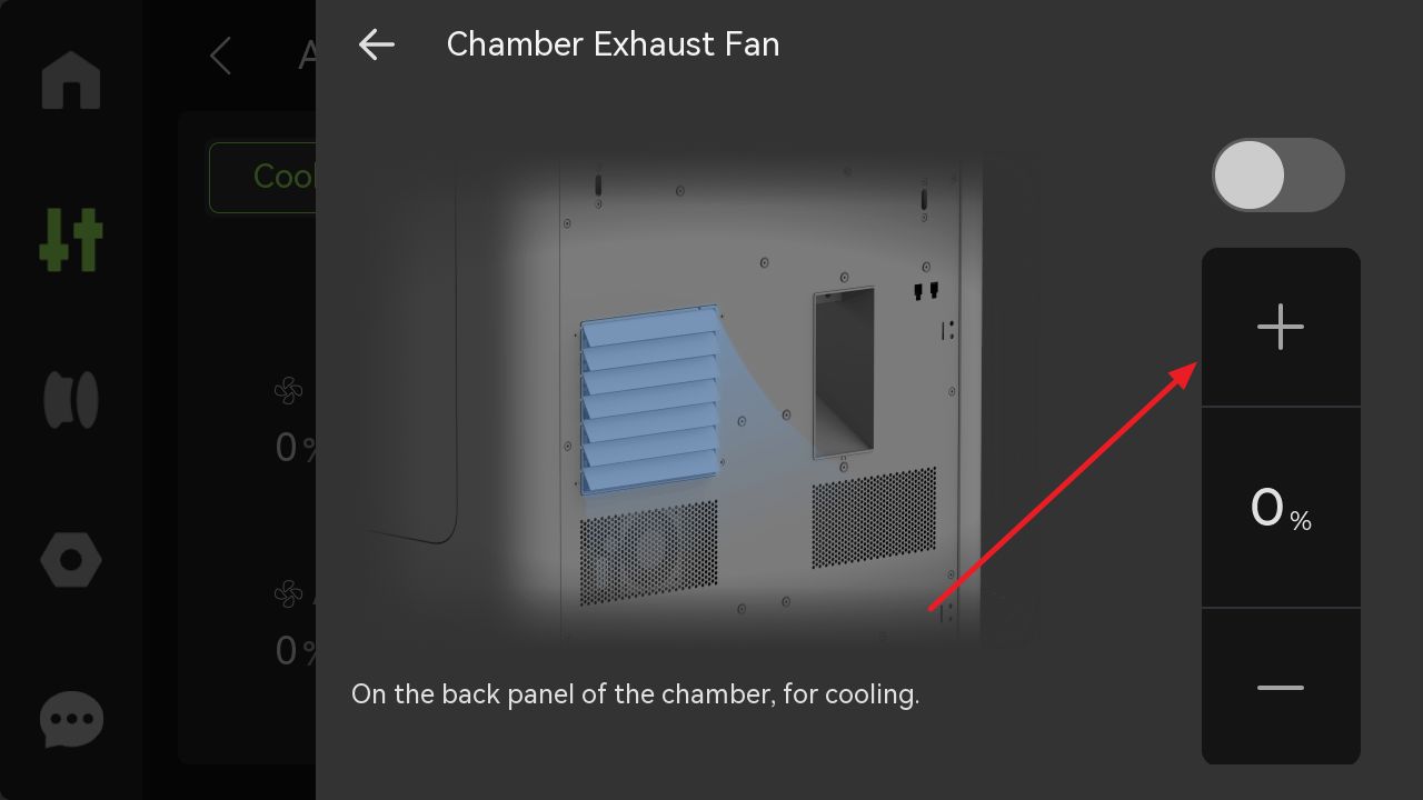
Power on the printer, navigate to Air Condition System => Cooling Mode => Exhaust. Correct installation is confirmed when observing normal opening/closing of the chamber exhaust.
 |
 |
¶ End Notes
We hope the detailed guide provided has been useful and informative to help you solve your problems.
To ensure that you operate safely and efficiently, if you have concerns or questions about any of the steps in the Guide, please contact our Customer Service team before you begin, we will be happy to answer your questions and provide support.
Click here to contact online technical support (service hours 9:00-21:00)