¶ Enclosure Top Frame
The enclosure top frame is installed on the top of the printer.
The spare parts for the enclosure top frame include the following:
- Enclosure Top Frame * 1
Pre-assembled with hall/flame sensor cables, top chamber LED and LED cover, PTFE tube coupler, automatic top vent, and laser air assist tube connector
- M3x10 screw - Used to fix the enclosure top frame) * 8
¶ When to Use
-
The enclosure top frame is damaged.
-
The hall sensor connector inside the top frame cover is damaged.
¶ Tools and materials needed
-
New enclosure top frame
-
H2.0 Allen Key
-
H1.5 Allen Key
¶ Safety Warning
IMPORTANT!
It's crucial to power off the printer before conducting any maintenance work, including work on the printer's electronics and tool head wires. Performing tasks with the printer on can result in a short circuit, leading to electronic damage and safety hazards.
During maintenance or troubleshooting, you may need to disassemble parts, including the hotend. This exposes wires and electrical components that could short circuit if they contact each other, other metal, or electronic components while the printer is still on. This can result in damage to the printer's electronics and additional issues.
Therefore, it's crucial to turn off the printer and disconnect it from the power source before conducting any maintenance. This prevents short circuits or damage to the printer's electronics, ensuring safe and effective maintenance. For any concerns or questions about following this guide, we recommend submitting a technical ticket regarding your issue and we will do our best to respond promptly and provide the assistance you need.
¶ Remove the Enclosure Top Frame
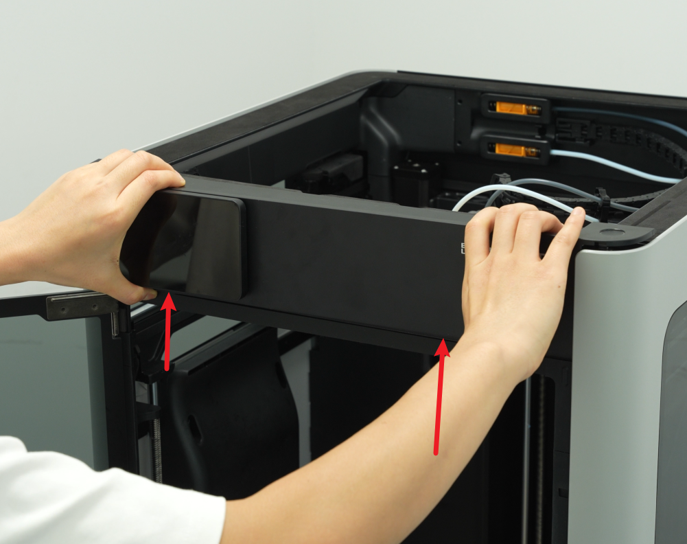
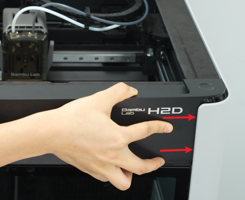
¶ Step 1: Remove the front cover and screen
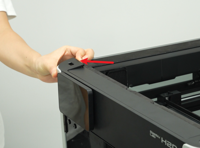
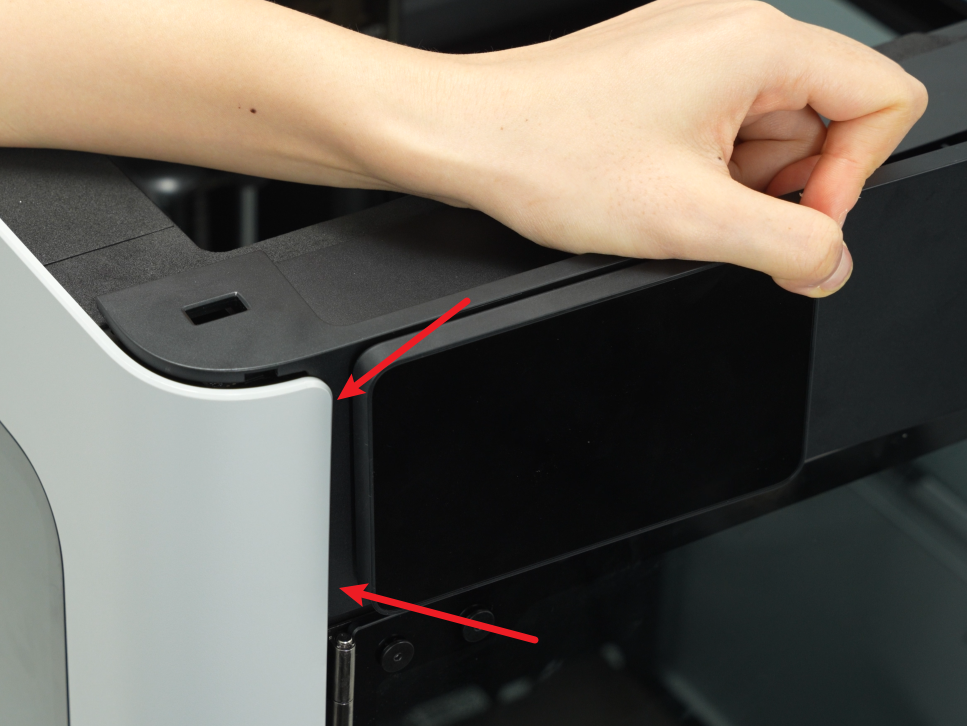
- Use an H1.5 Allen key to remove a fixing screw (BT2×12), then hold the buckle on the left side of the front cover with your hand, snap off the top left side of the front cover, and then snap open the top right side:
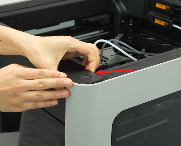
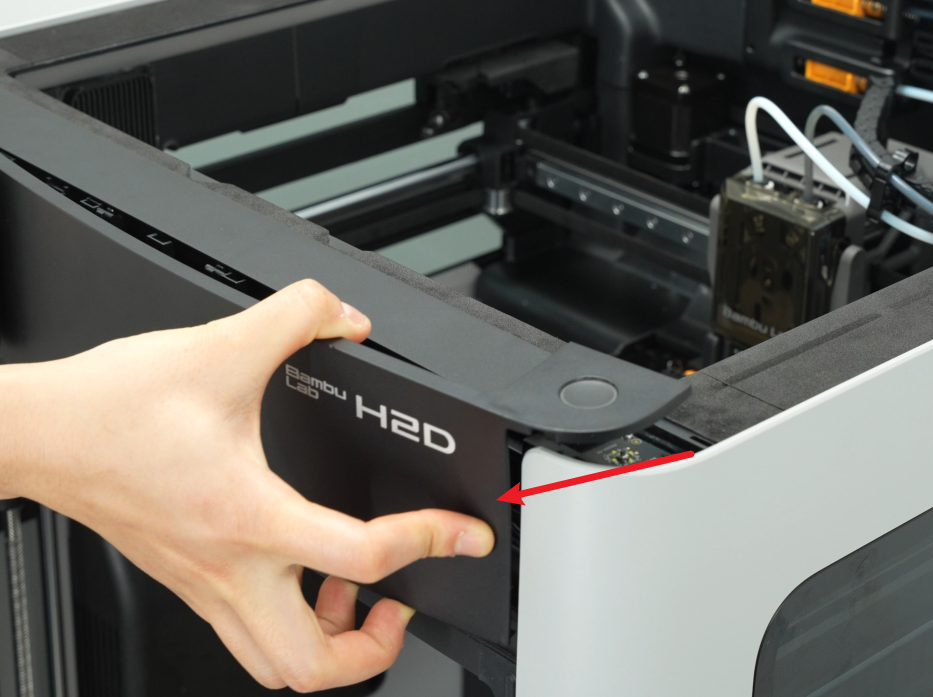
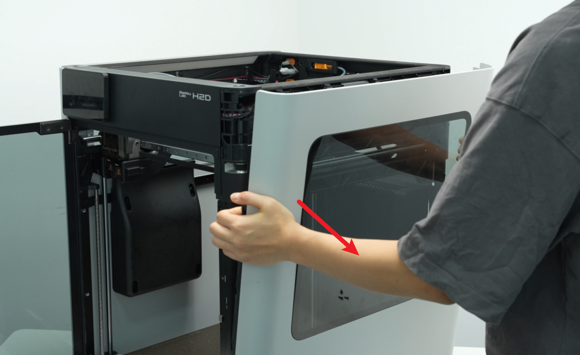
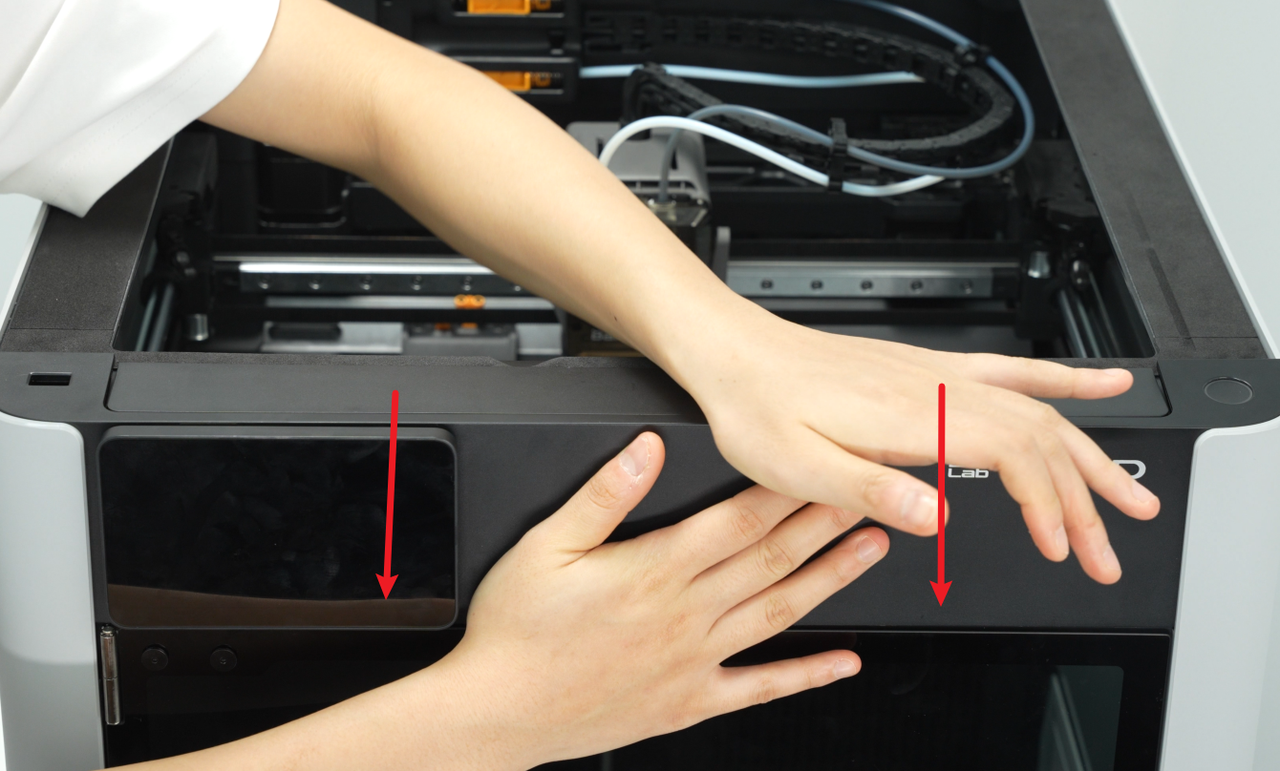
- Then place your thumbs on the bottom of the front cover and push upwards to unlock the front cover card. Then hold the right side of the front cover to bend it slightly and pull the right side of the front cover out from under the right side panel.
Please pull it out carefully to avoid damaging the screen FPC!
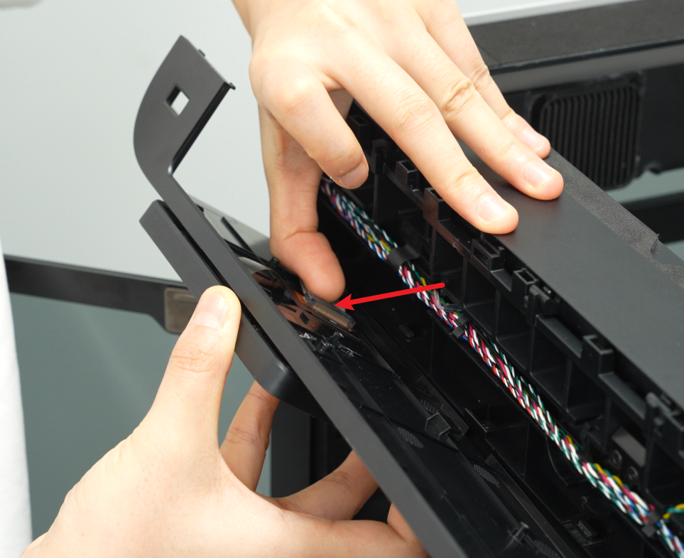
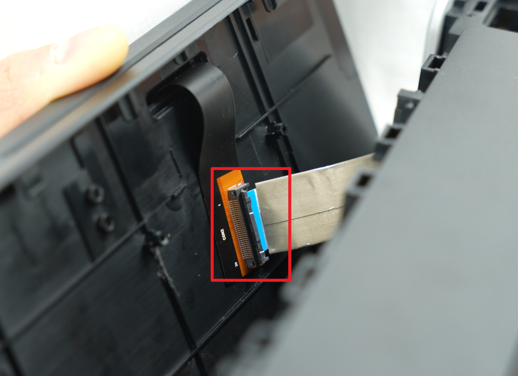
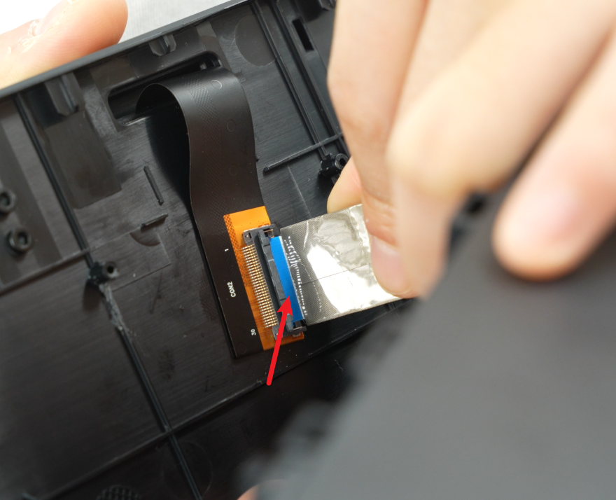
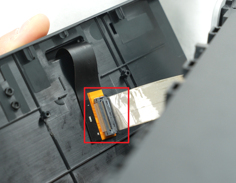
- After pulling the right side of the front cover out of the printer, carefully flip the front cover over to expose the interface between the screen and the screen FPC. Unfasten the buckle of the screen cable upwards, and then remove the screen cable from the buckle.
Note: You do not need to separate the front cover and screen for subsequent installation.
If you have any questions about the process of removing the front cover, you can refer to this wiki article: Replace H2D Front Cover
¶ Step 2: Remove the rear panel
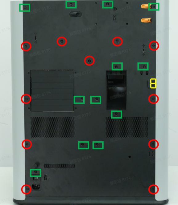
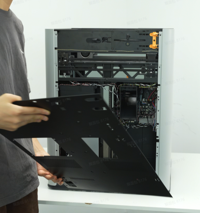
You can use an H2.0 Allen key to remove the rear panel fixing screws and then remove the rear panel. You can refer to this wiki for detailed steps to remove the rear panel: 更换 H2D 背板
¶ Step 3: Remove the right side panel
You can refer to this Wiki for detailed steps on how to remove the right side panel: Replace H2D Left/Right Side Panel
Be careful when removing it to avoid pulling the hall cable.

¶ Step 4: Remove the left side panel/front glass door
Since you need to remove the front glass door first when removing the left side panel, you can remove the front glass door and the left side panel together in this step.
You can refer to this wiki for detailed steps on how to remove the left side panel/front glass door:Replace H2D Left/Right Side Panel
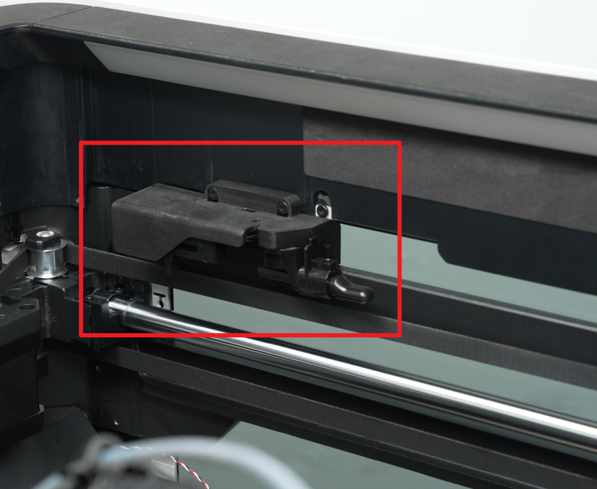
¶ Step 5: Remove the left/right filament cutter stoppers
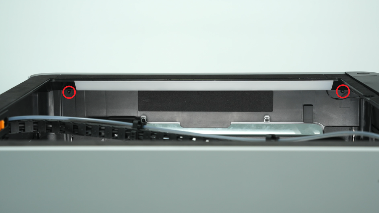
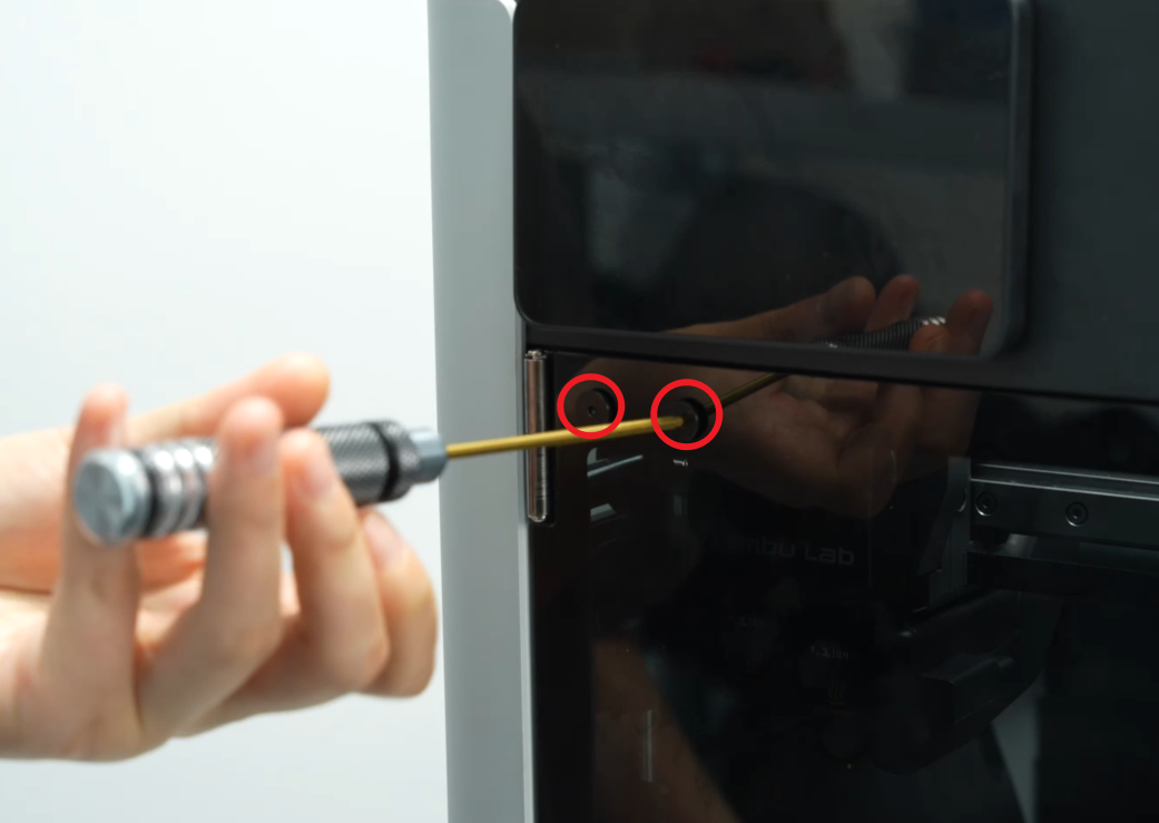
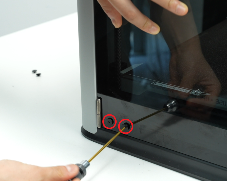
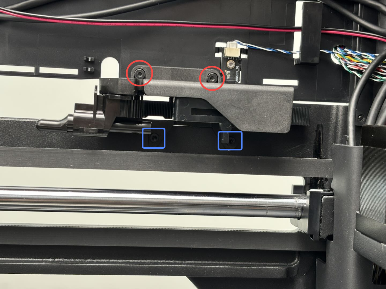
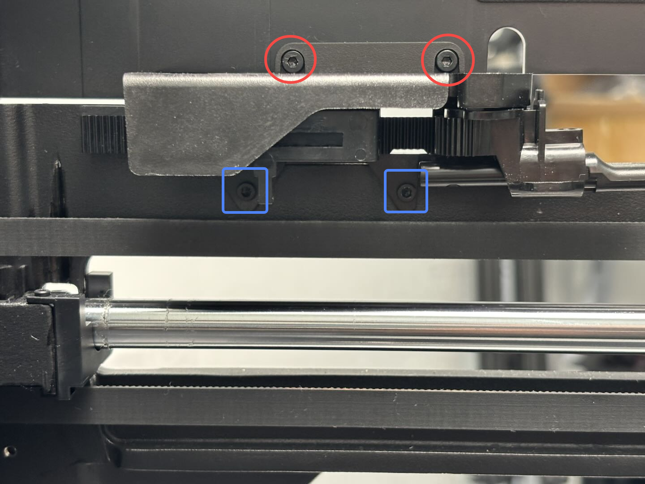
You can use an H2.0 Allen key to remove the four screws that hold the cutter stoppers in place (red circle: BT2.6x8; blue box: M2.5x5).
Note: The screw holes for the left and right filament cutter stoppers are similar, with two in the upper row and two in the lower row.


¶ Step 6: Remove the filament buffer
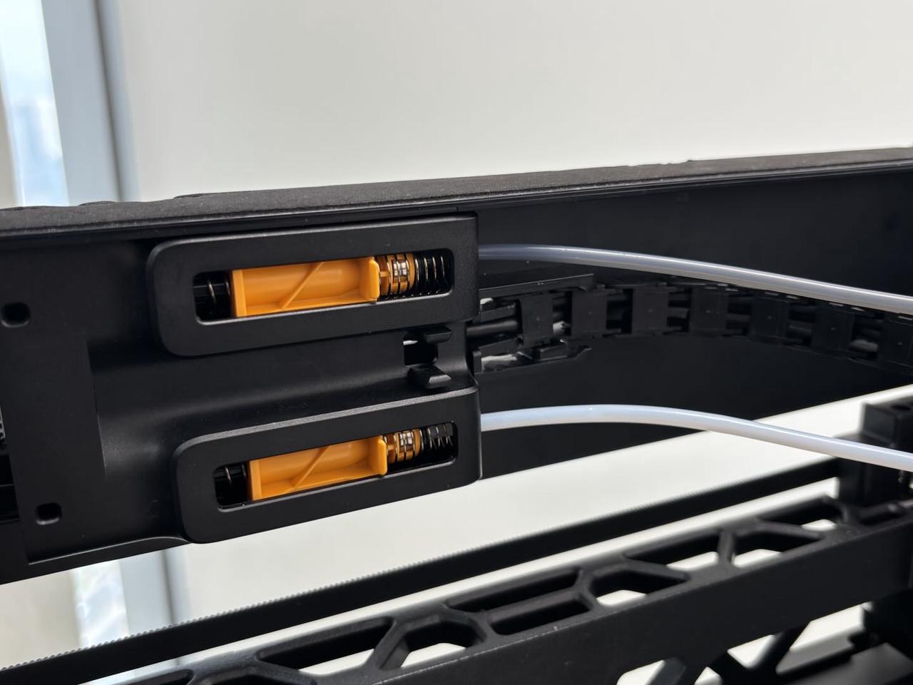
- Push the filament buffer slider to the far right, then press the pneumatic connector and disconnect the two PTFE tubes from the filament buffer in turn;
- Use an H2.0 Allen key to remove the four screws that fix the buffer. Then, pull out the connectors on both sides of the buffer connector and remove the buffer.


¶ Step 7: Disconnect the cables on the AP board
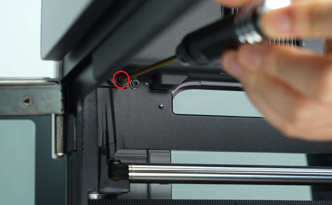
Use an H2.0 Allen key to loosen 1 fixing screw (BT2.6x8), and then remove the AP board cover from the side near the front door.


Unplug the connection cables on the AP board one by one.
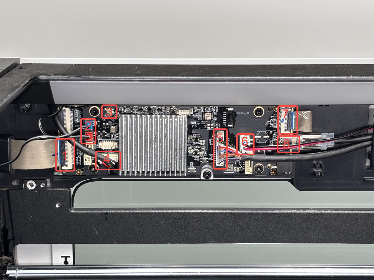
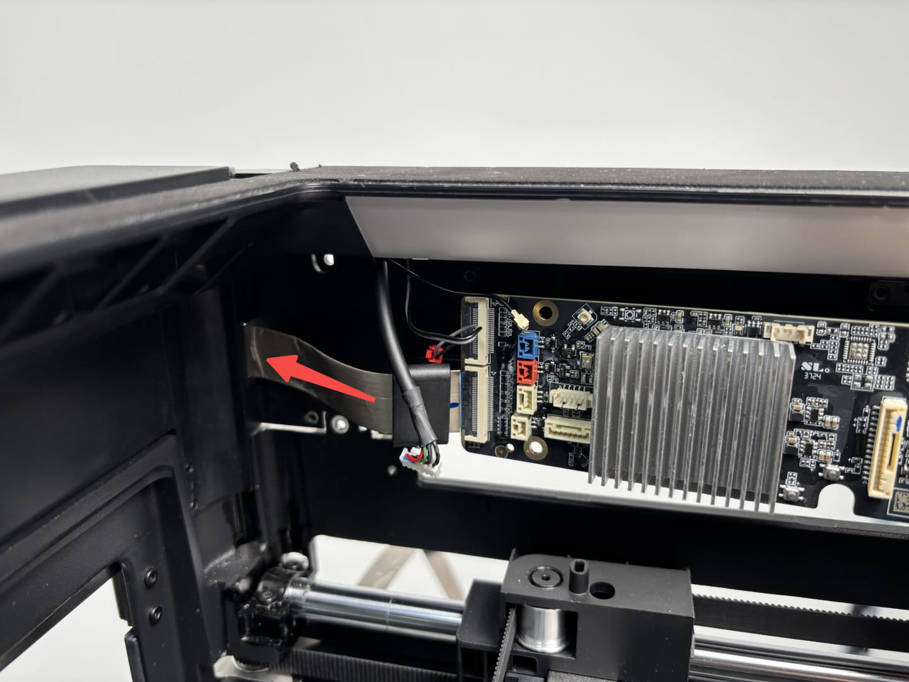
- Screen FPC:
No need to disconnect it, you can remove it together with the AP board. Please be careful with the magnetic ring on the screen FPC to avoid dropping it.
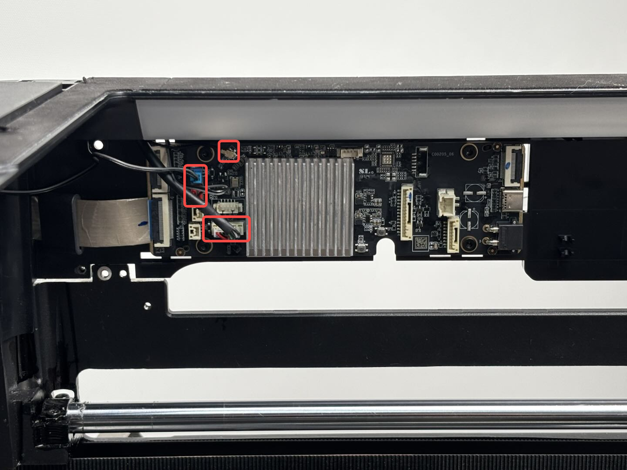
- Left and right LED light connectors(Blue:right LED light;Red:left LED light):
You can press the buckle of the LED light cable connector and then pull out the connectors.
The left/right LED light connectors (red/blue) can be pulled out in the same way.
- Wifi antenna:
You can unlock the Wifi antenna by simply pulling the buckle of the Wifi antenna outwards.
- USB port board:
You can unlock the USB port board connector by simply pulling the buckle of the connector outwards.
- MC-AP cable(communication):
You can unlock the MC-AP cable by simply pulling the buckle of the cable outwards.
- MC-AP cable(power supply):
You can unlock the MC-AP cable by simply pulling the buckle of the cable outwards.
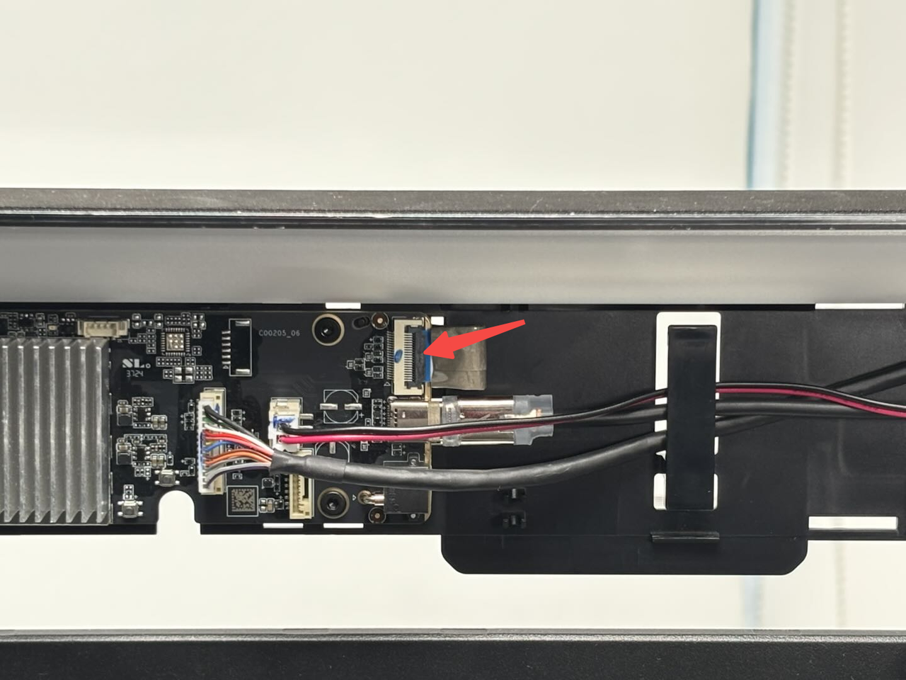
- Live view camera connector:
Unfasten the buckle that connects the live view camera connector to the AP board, and then remove the live view camera connector from the interface on the AP board;
- USB-C cable
Unplug the USB-C cable parallel to the AP board.
If your AP board has a ground wire at the bottom left fixing screw, you can separate the ground wire from the AP board when you remove the AP board fixing screw.
¶ Step 8: Remove the AP board
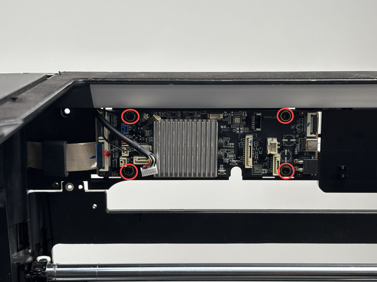
Use an H2.0 Allen key to loosen the 4 fixing screws (BT3×5), and then remove the AP board.
Note: You can remove the magnetic ring from the screen FPC first to prevent it from falling during disassembly and assembly.

¶ Step 9: Disconnect the USB-C cable/MC-TH cable/cable chain tail
- Remove the USB-C cable from the cable clip; then press the buckle on the connector to disconnect the MC-TH cable from the toolhead to MC board cable;
- Hold the cable chain and pull its tail out of the upper cover;
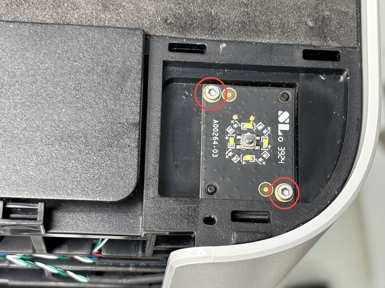
¶ Step 10: Remove the USB port board and Start/Pause button
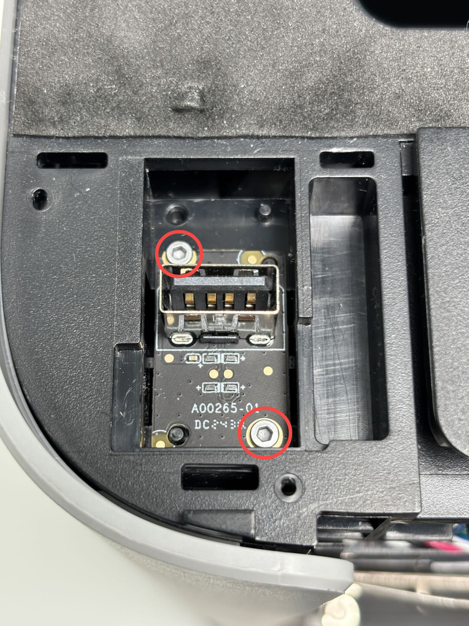
- Use an H1.5 Allen key to loosen the two fixing screws (BT2x5), then remove the USB port board and the USB port board connector together;

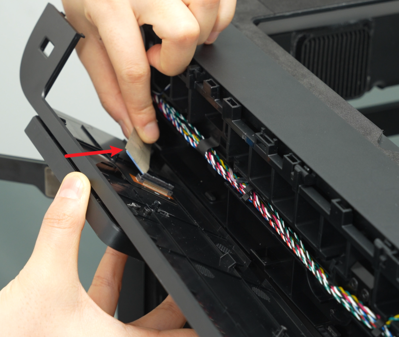
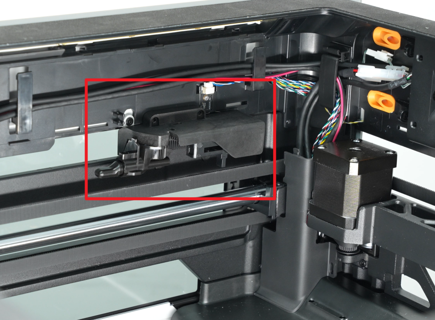
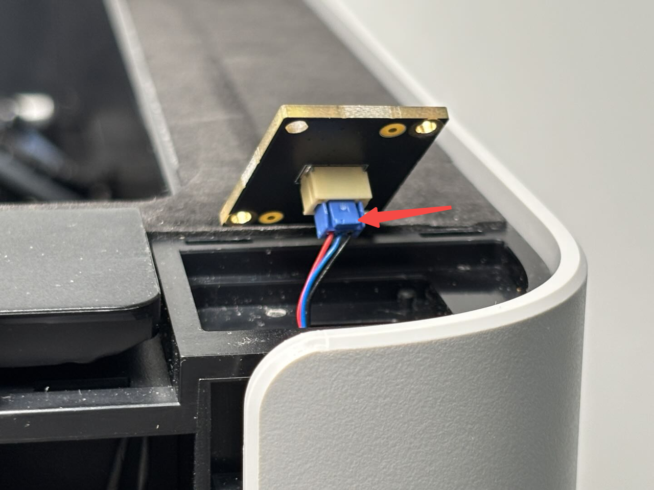
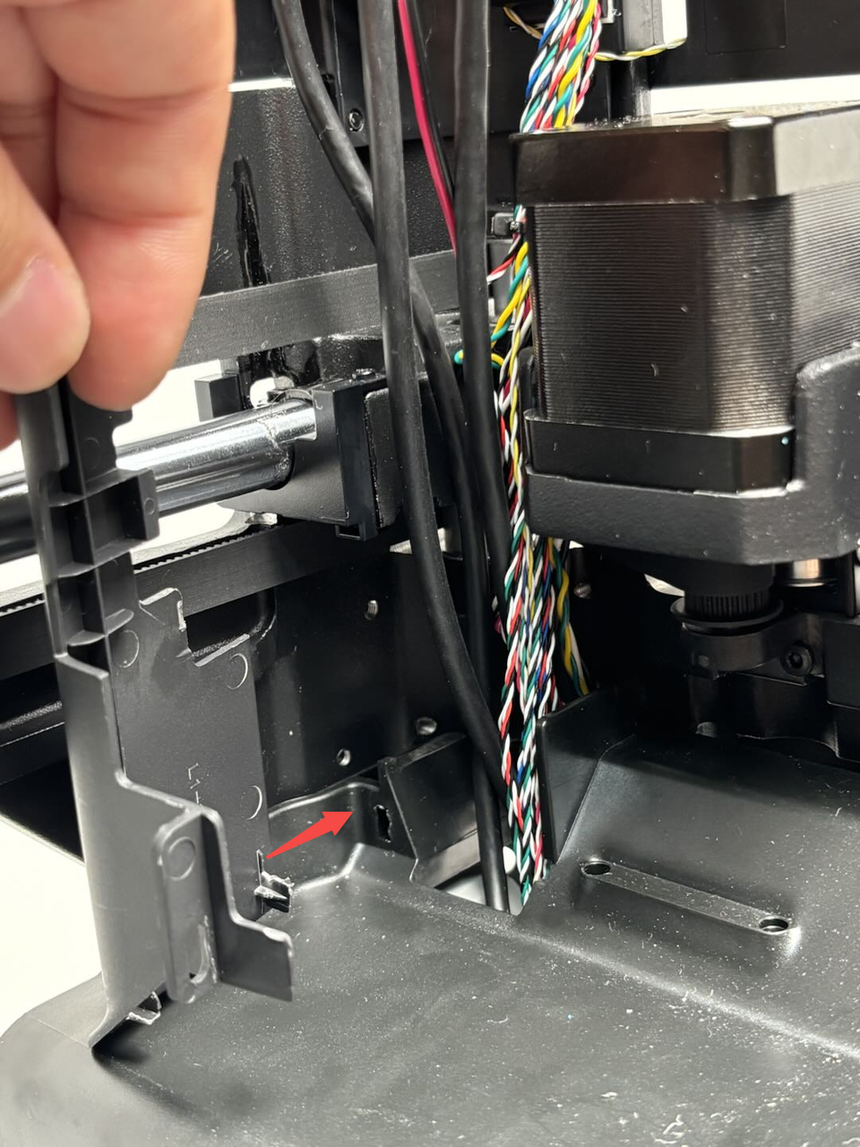
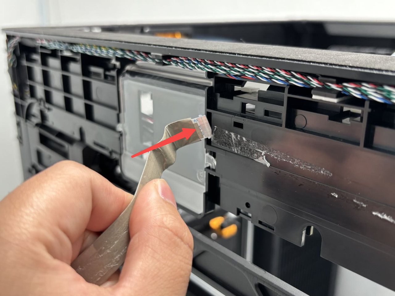
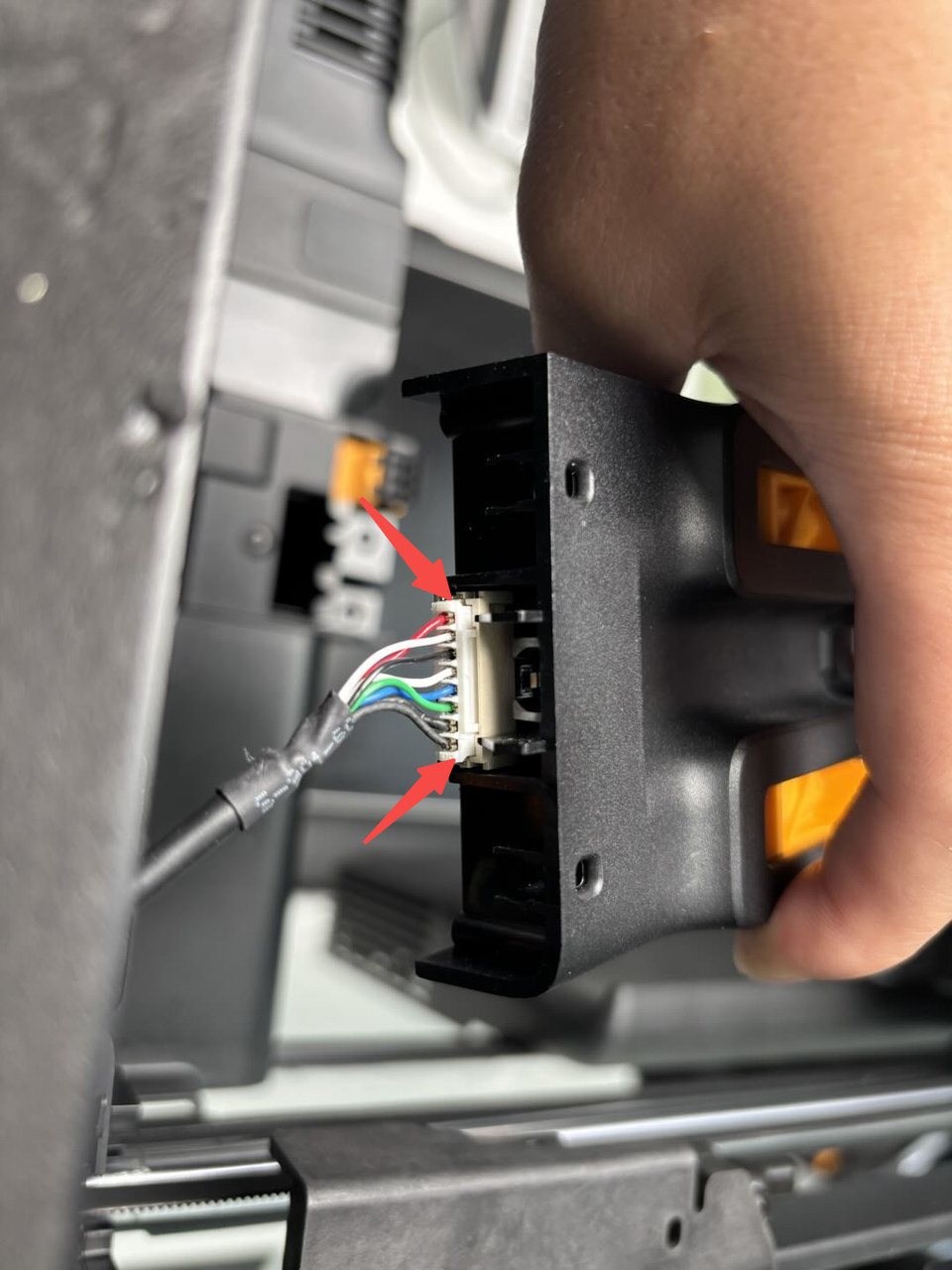
- Use an H1.5 Allen key to loosen the two Start/Pause button fixing screws (BT2x5). Press the tab on the connector (arrowed) and disconnect the cable from the Start/Pause button.
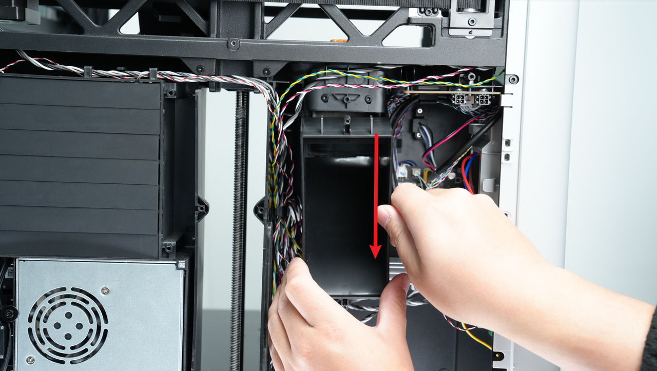
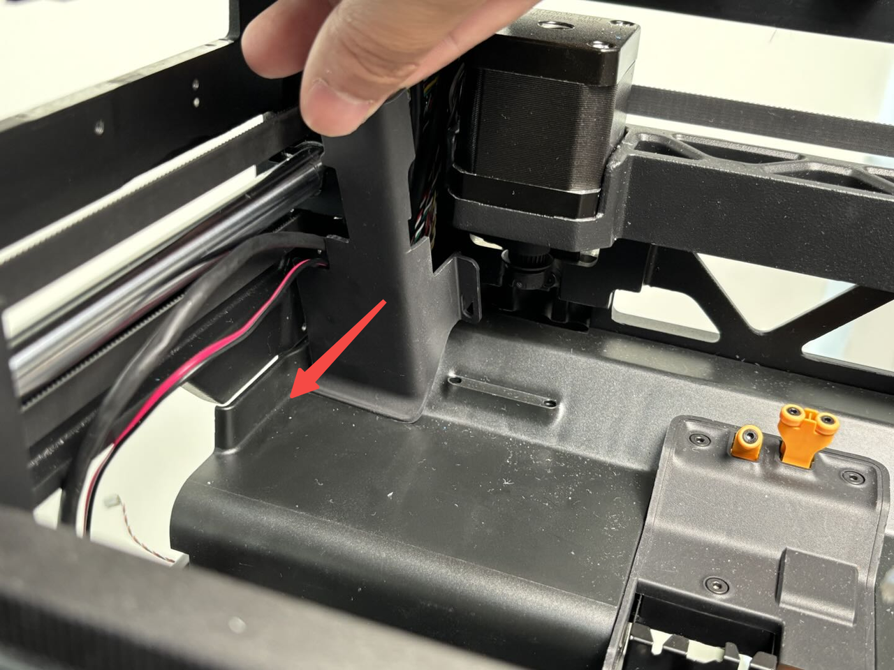
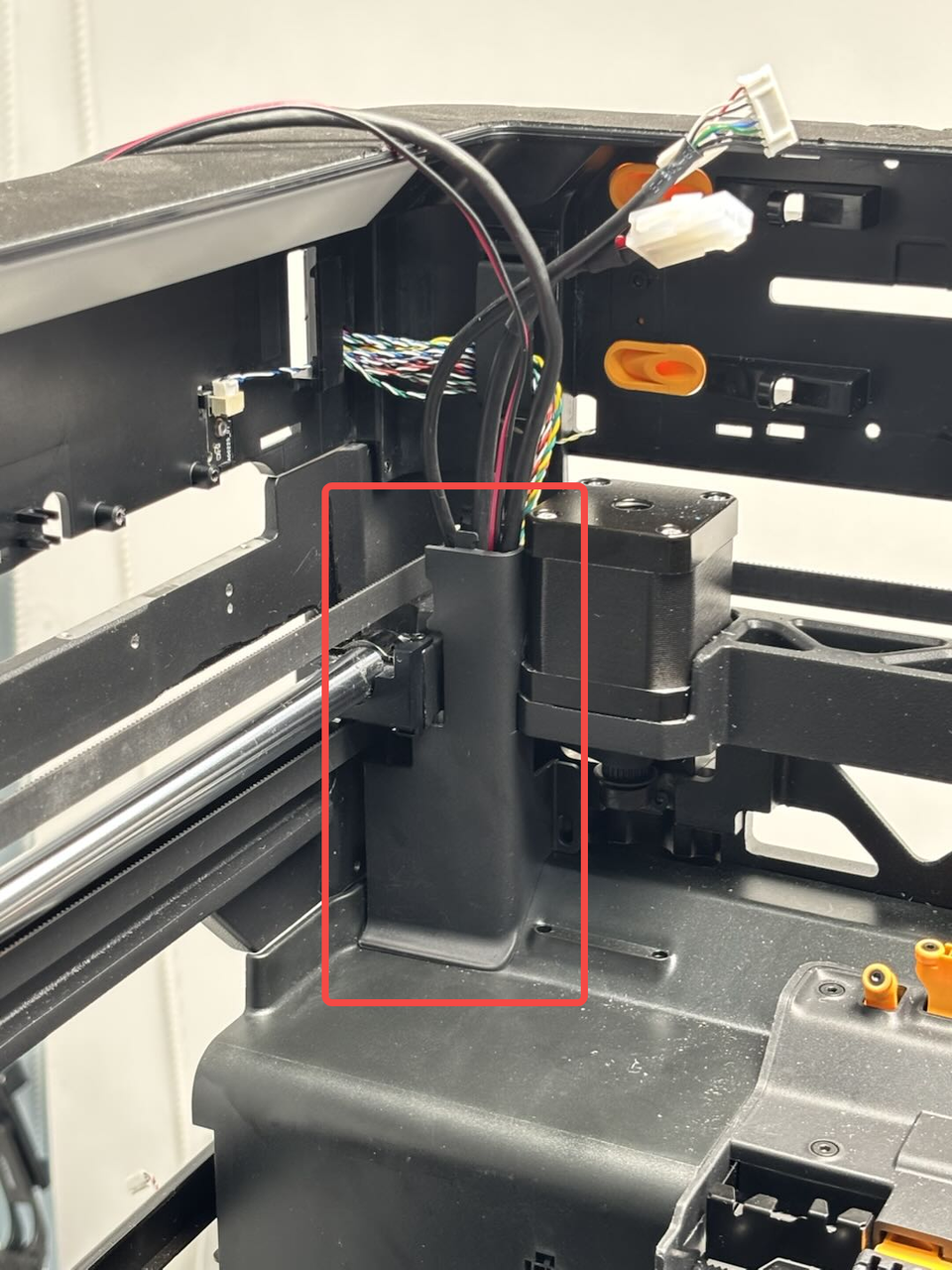
¶ Step 11: Remove the purge chute
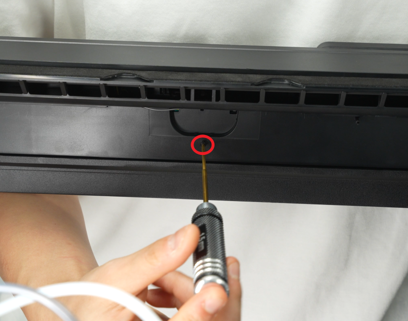
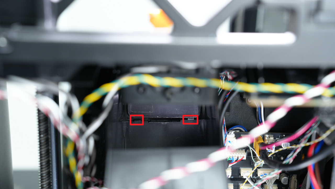
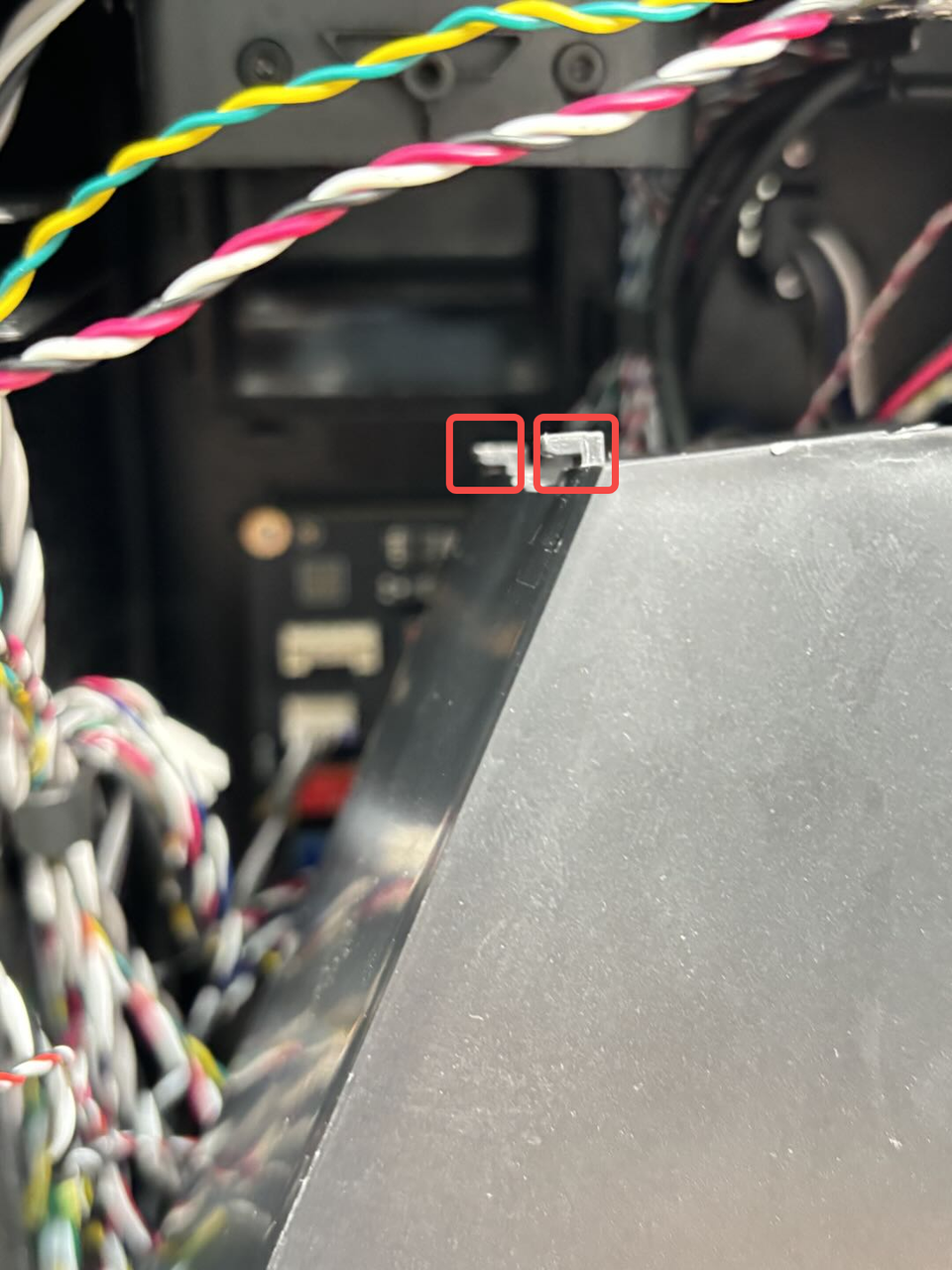
Use an H2.0 Allen key to remove 1 screw (BT3x8), then pull it down to remove the purge chute, until you can see the two clips of the purge chute, then take out the purge chute.
In addition to being fixed by the screws on the top, the purge chute also has two clips on the bottom that are fastened to the lining.

¶ Step 12: Remove the cables
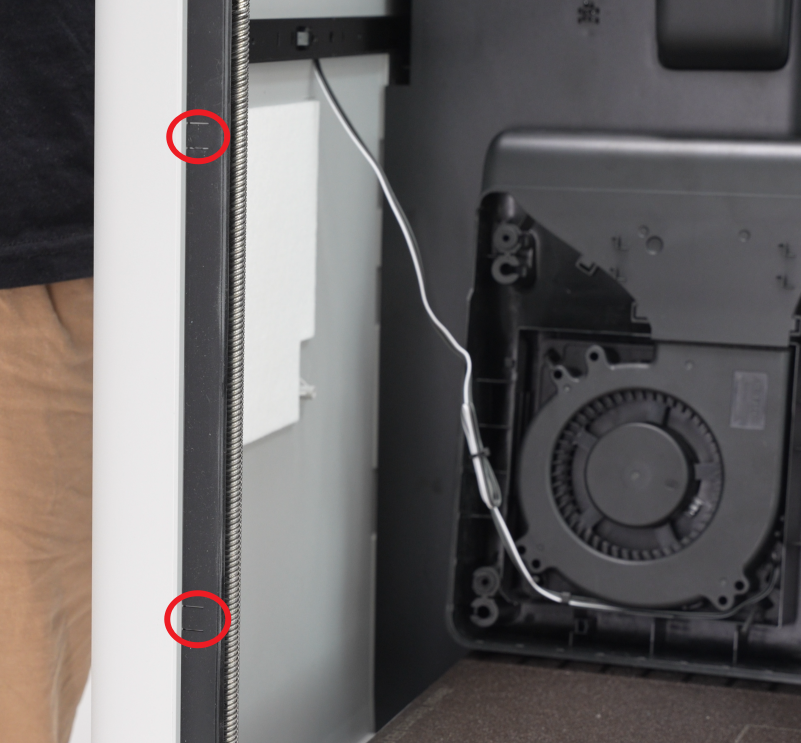
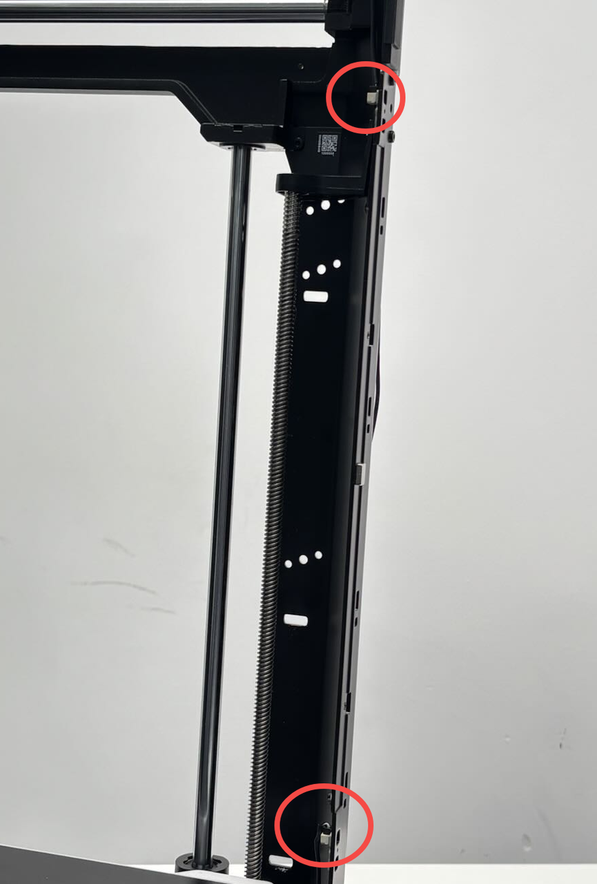
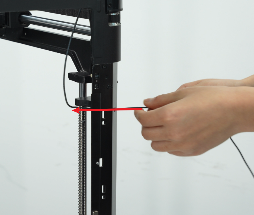
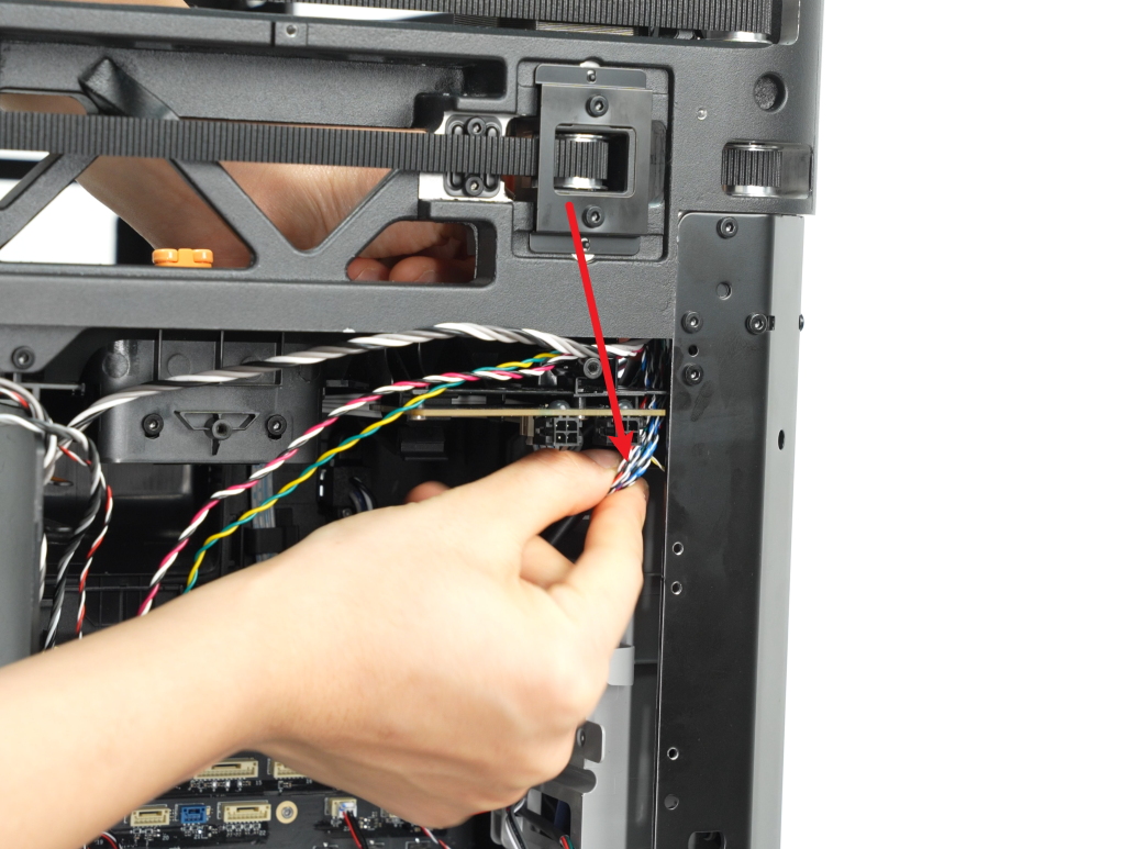
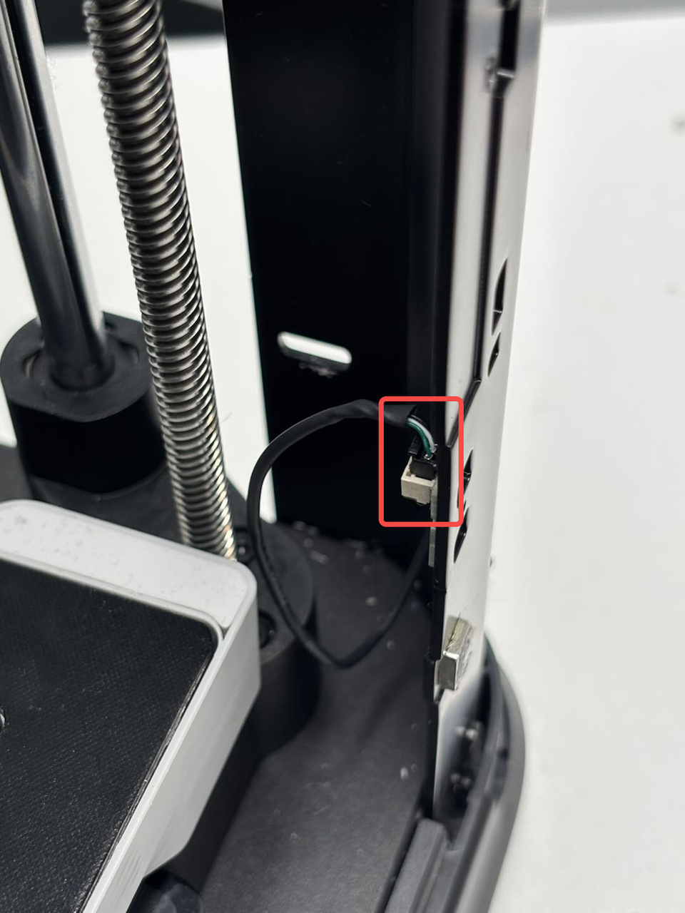
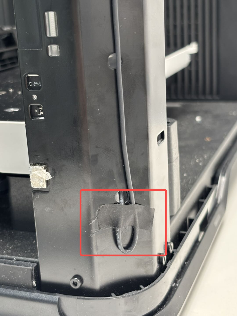
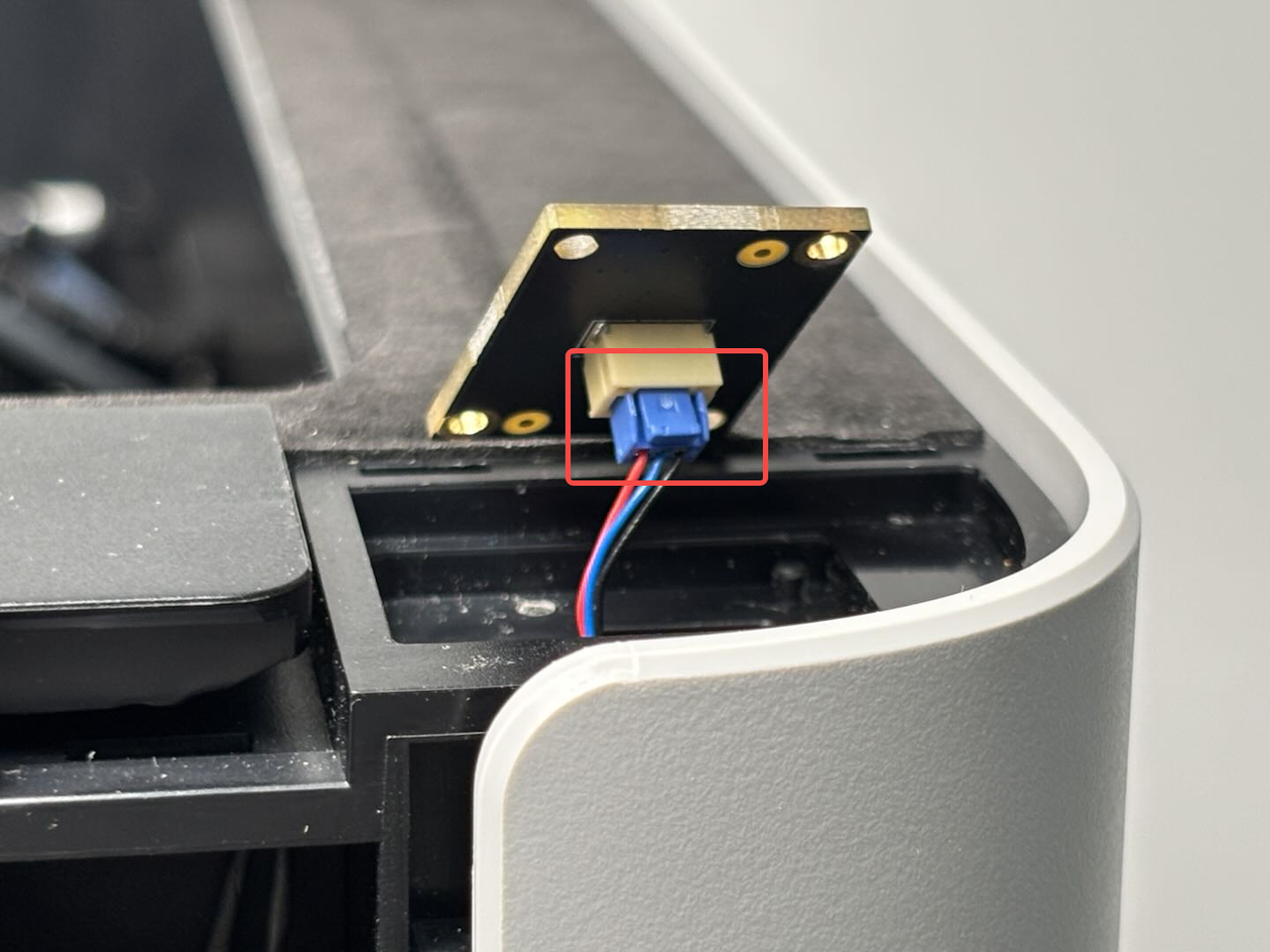
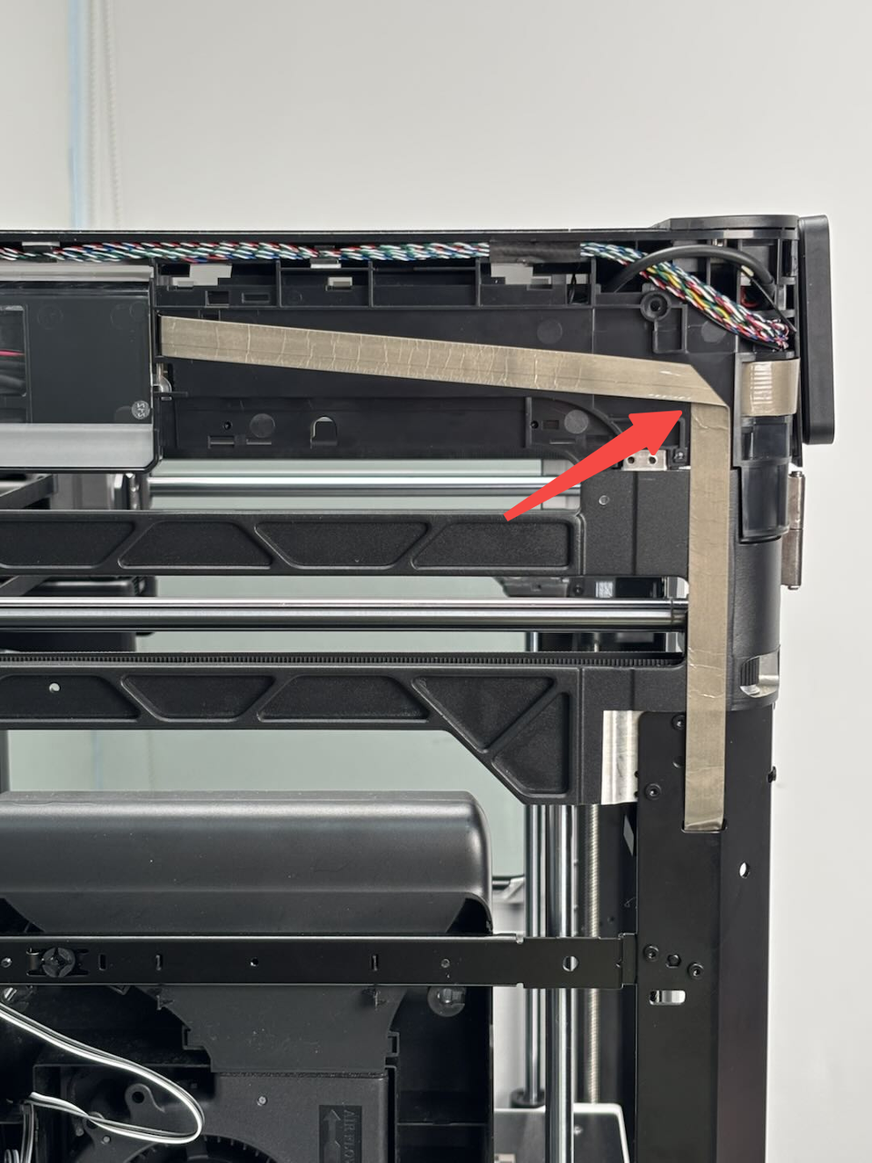
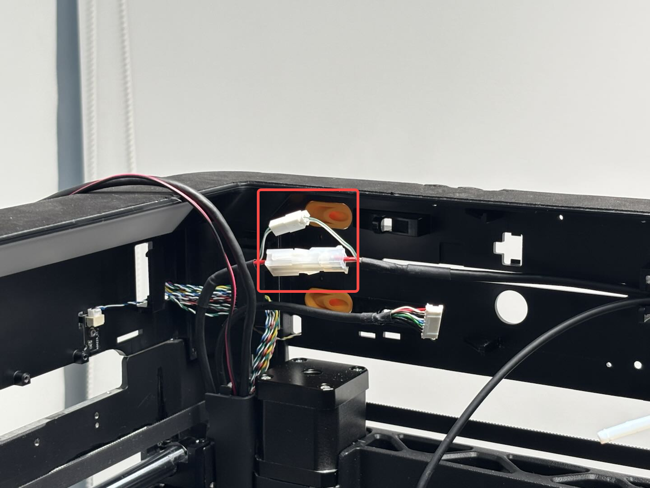
- Disconnect the two hall effect sensors on the inside of the right pillar from the connector: first tear off the tape on the pillar (the tape can remain on the pillar), leaving some margin for the bottom hall connector to facilitate disconnection, and then pull the bottom hall sensor out of the small hole;
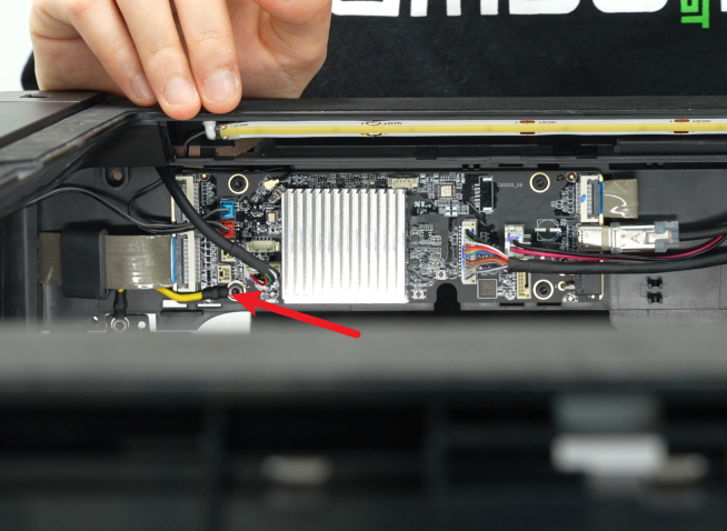
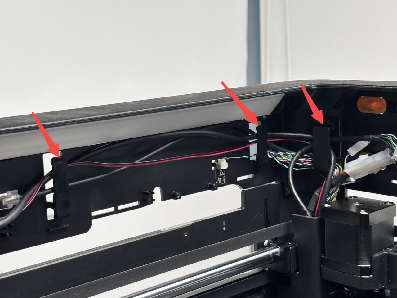
- Remove the cable cover first, and then remove the MC AP cables from the cable clip on the upper frame;
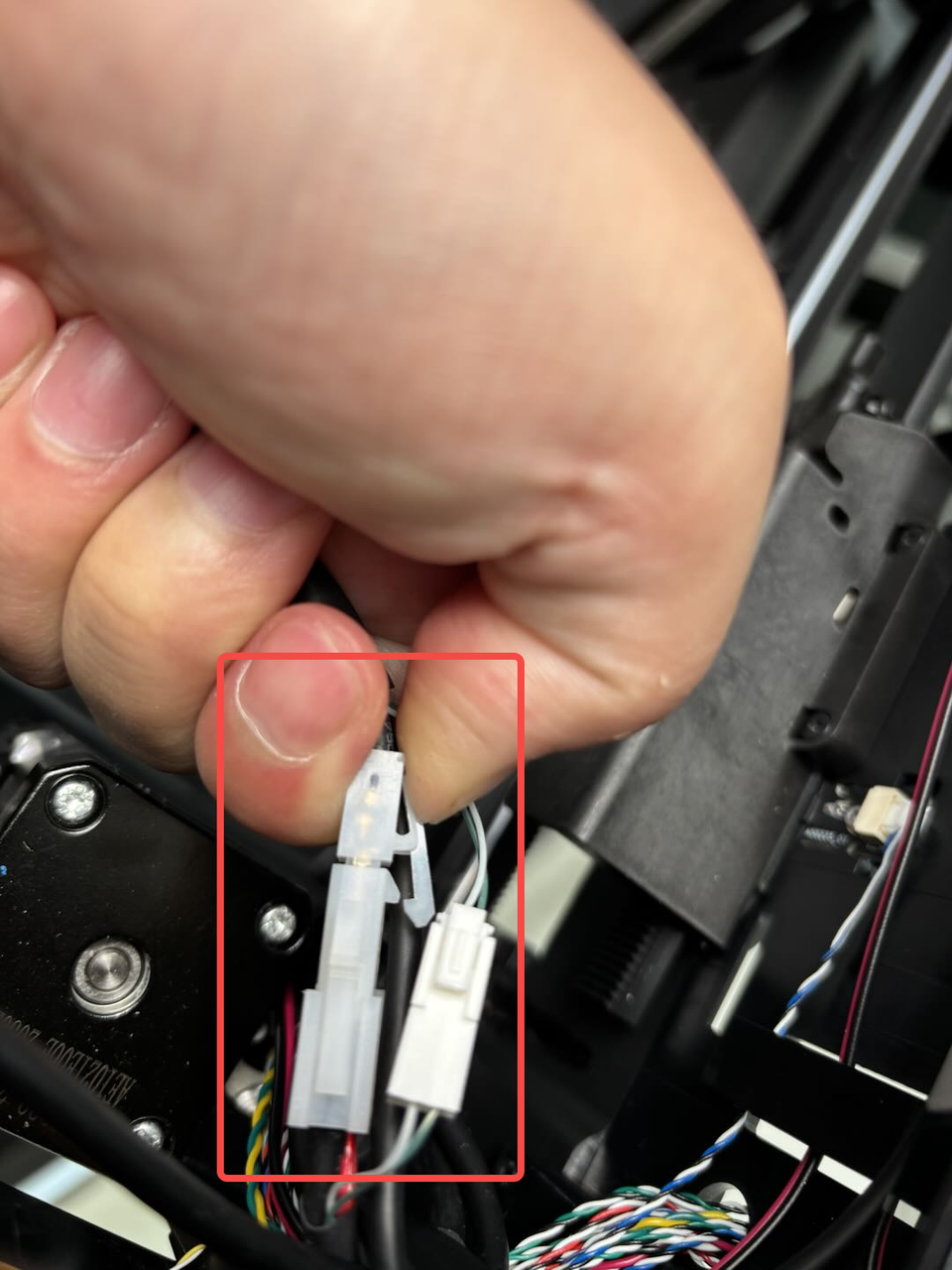
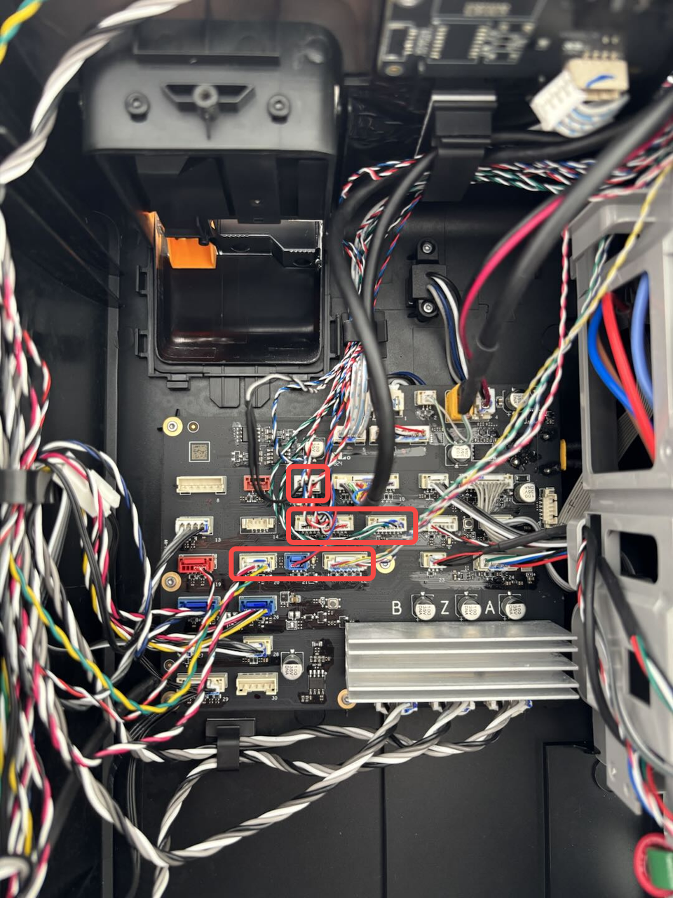
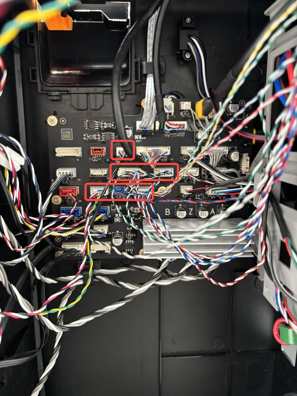
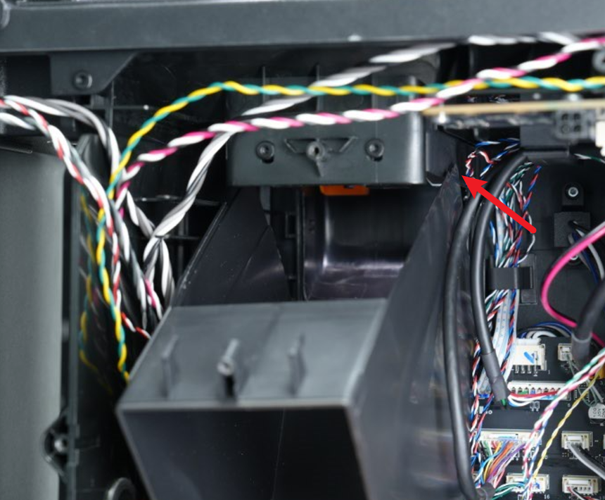
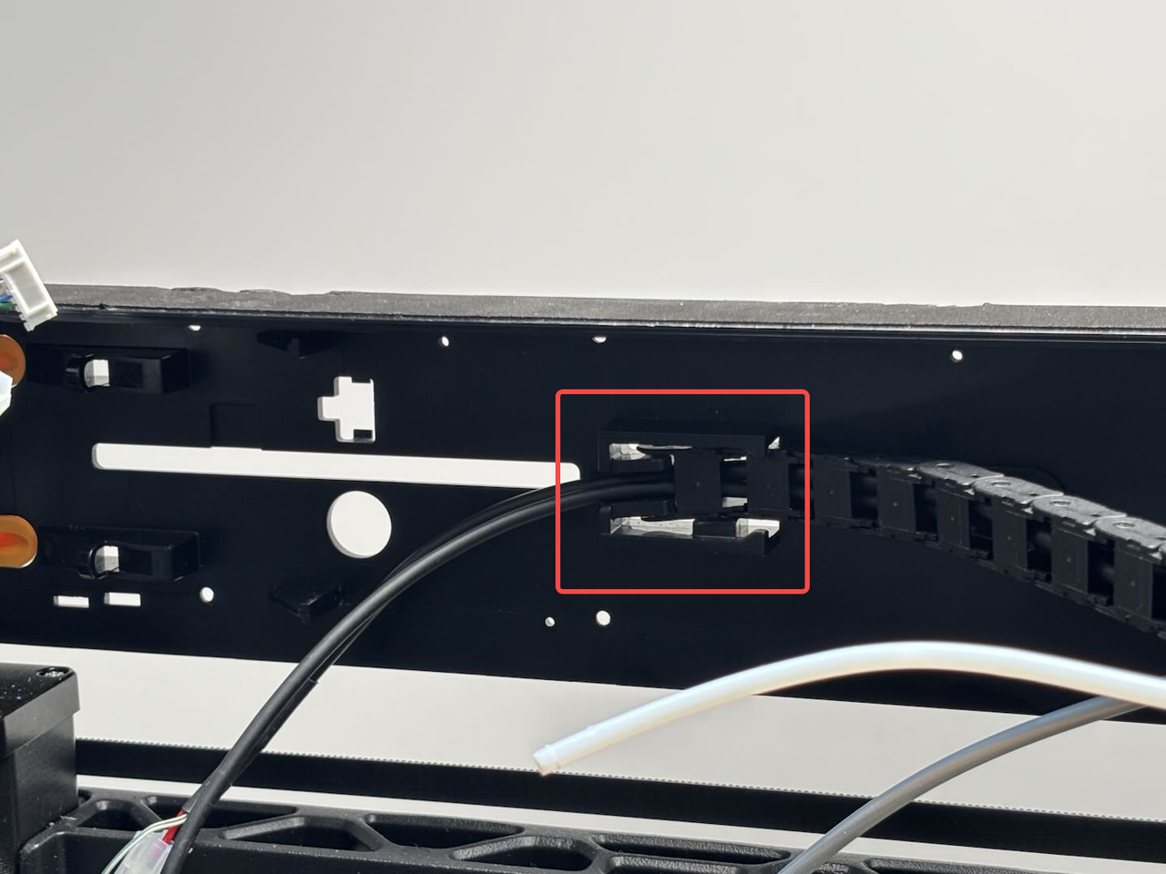
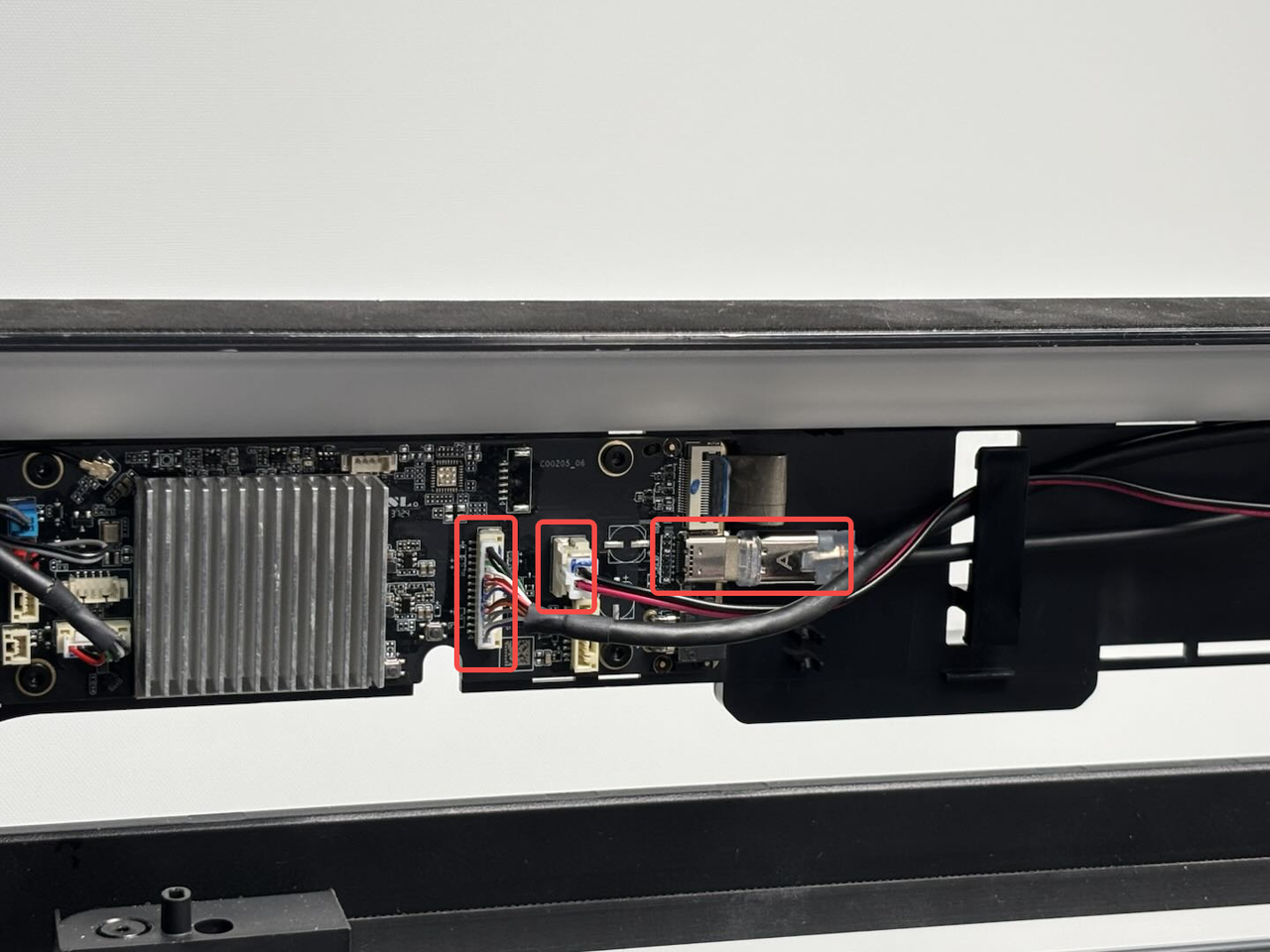
- Disconnect the connectors shown in the figure below from the MC board and remove them from the cable clips;

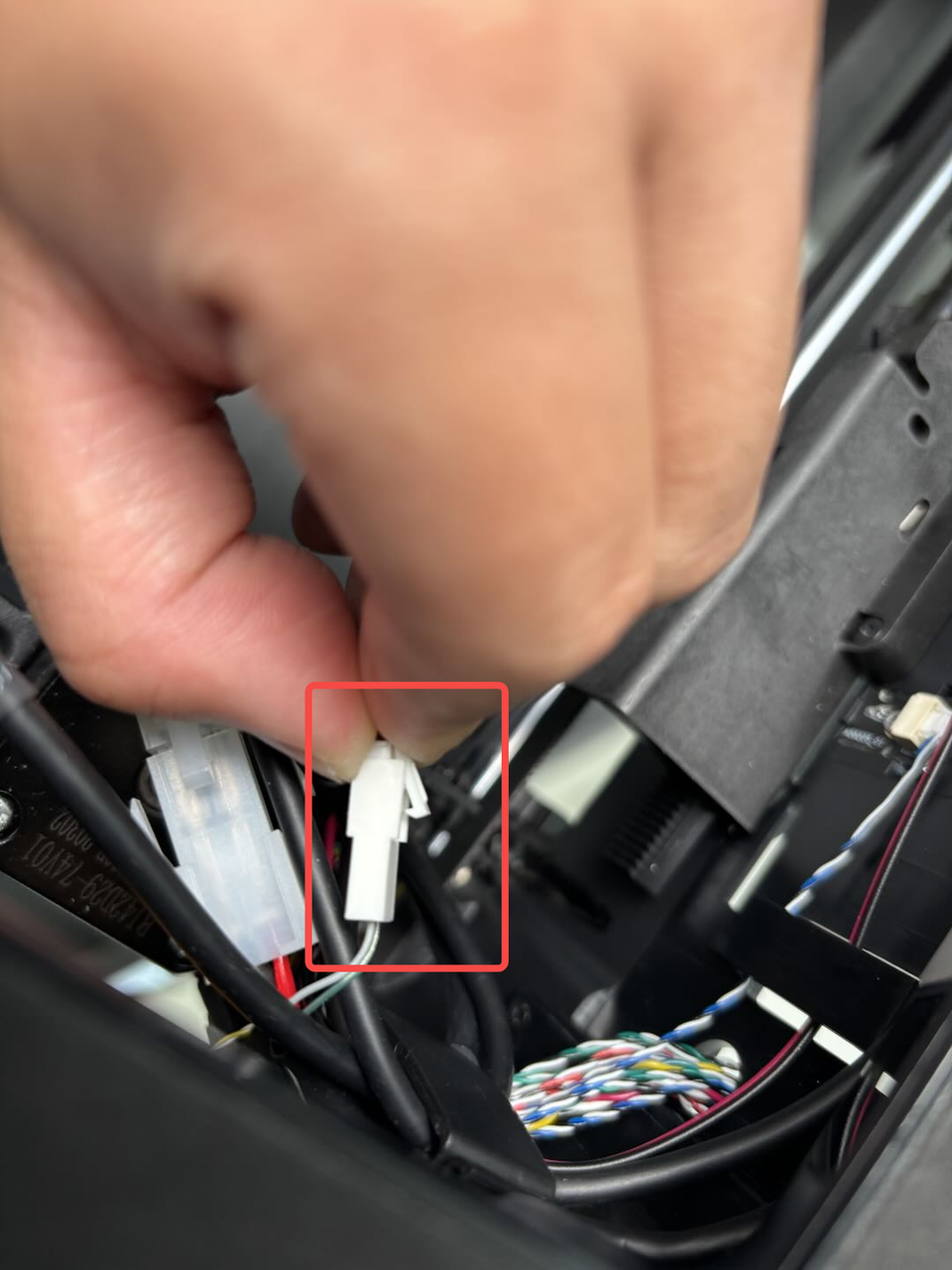
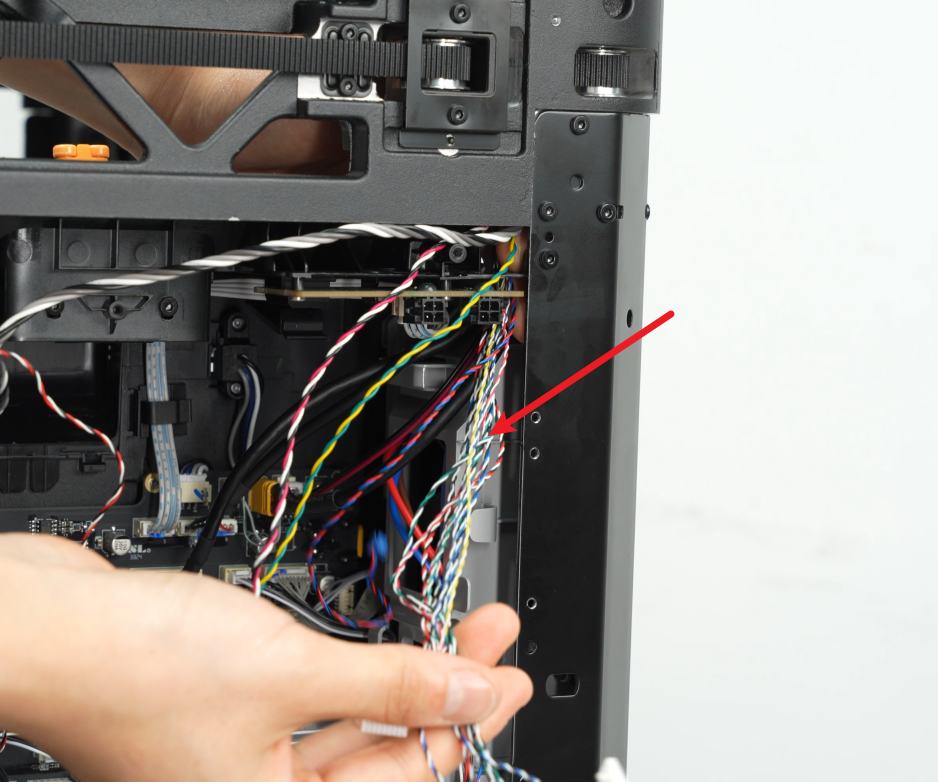
- Remove the cables shown in the figure below from the clips of the AC board cover, and then pull the cables out of the left lining.
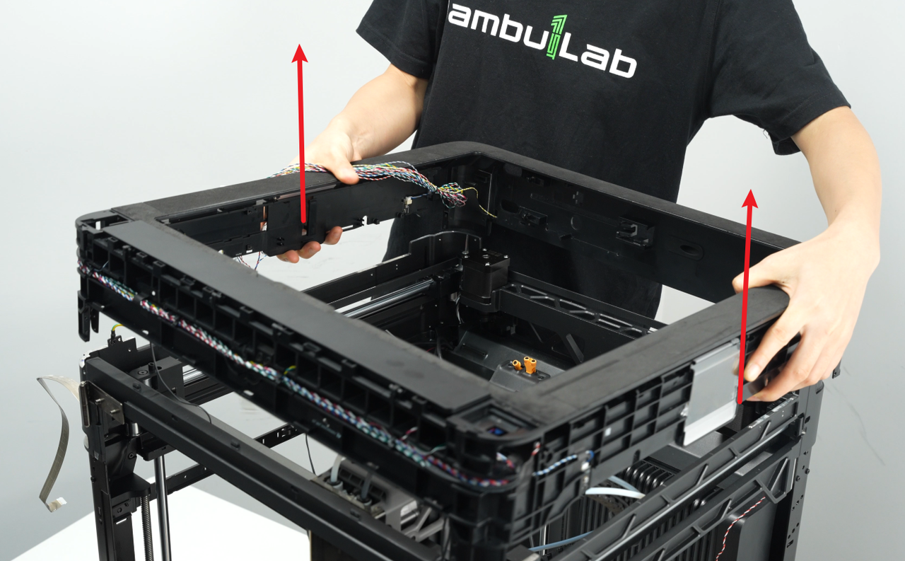
¶ Step 13: Remove the enclosure top frame
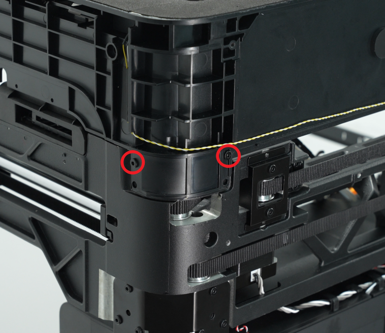
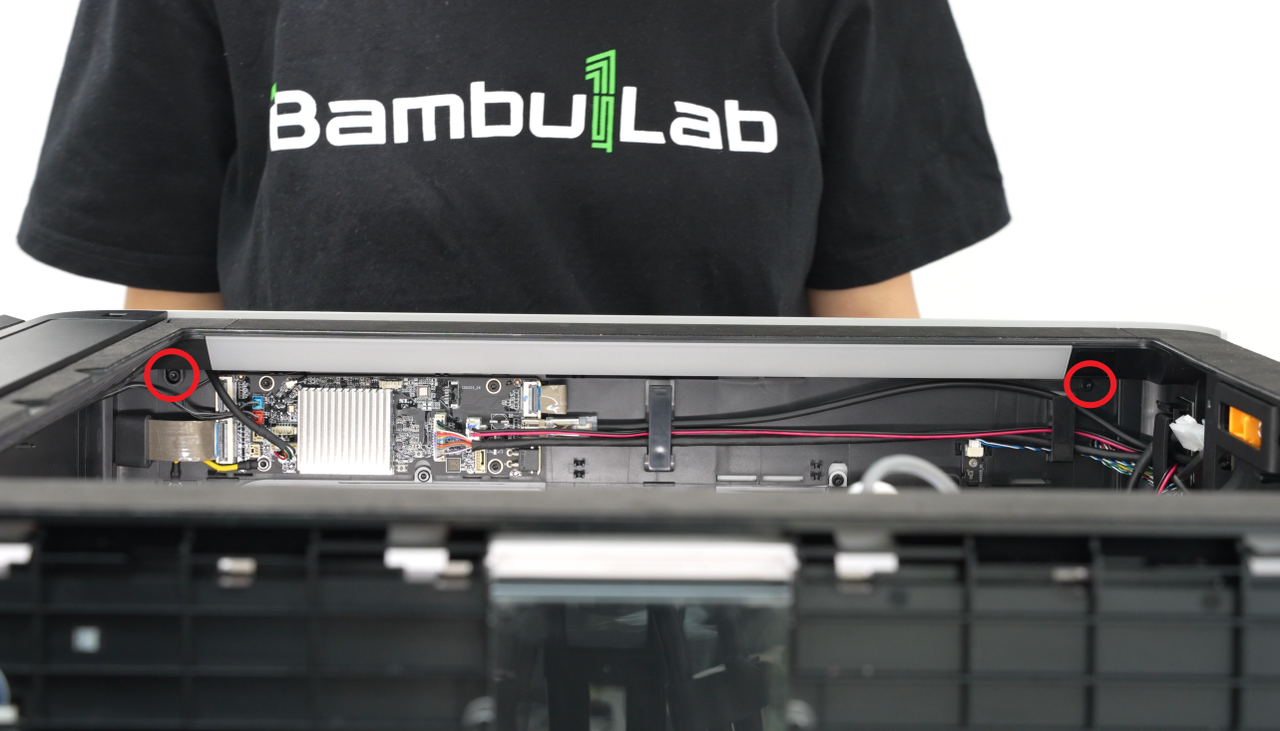
- Use an H2.0 Allen key to remove the eight fixing screws (M3x10), two screws for each pillar;

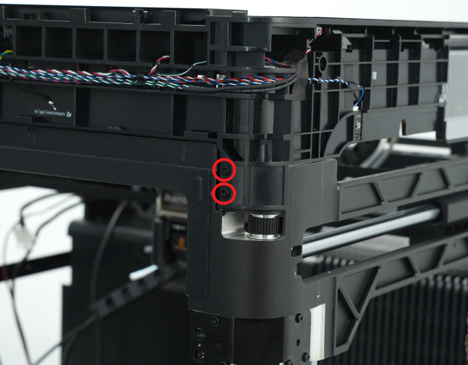
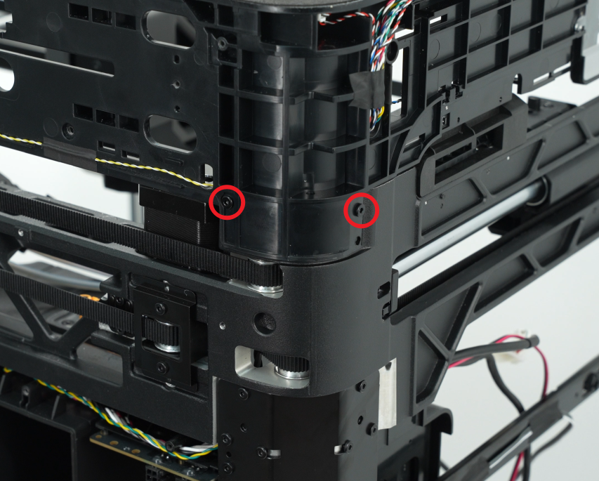

- Lift the enclosure top frame upwards to remove it.
¶ Install the Enclosure Top Frame
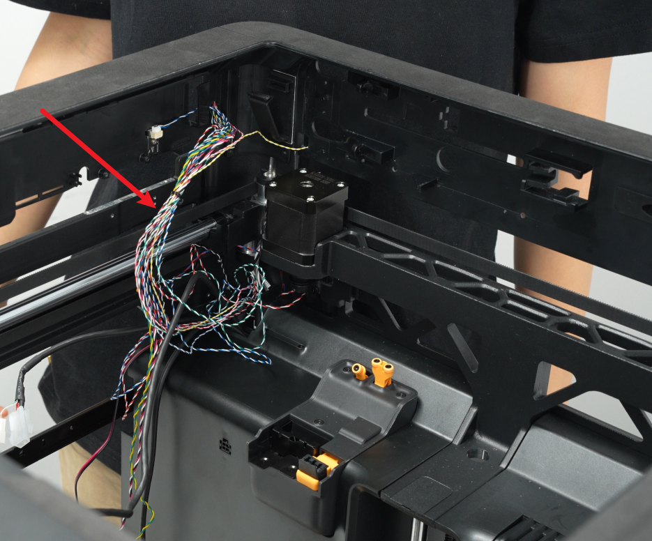
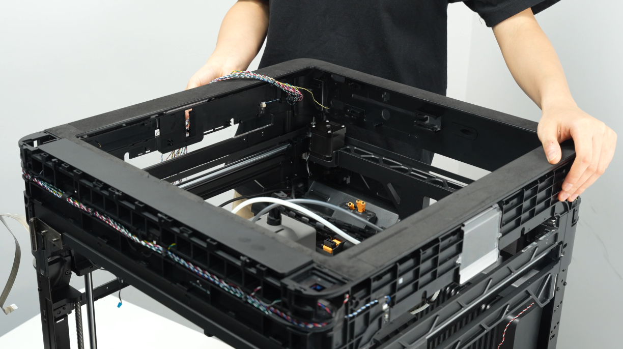
¶ Step 1: Install the enclosure top frame
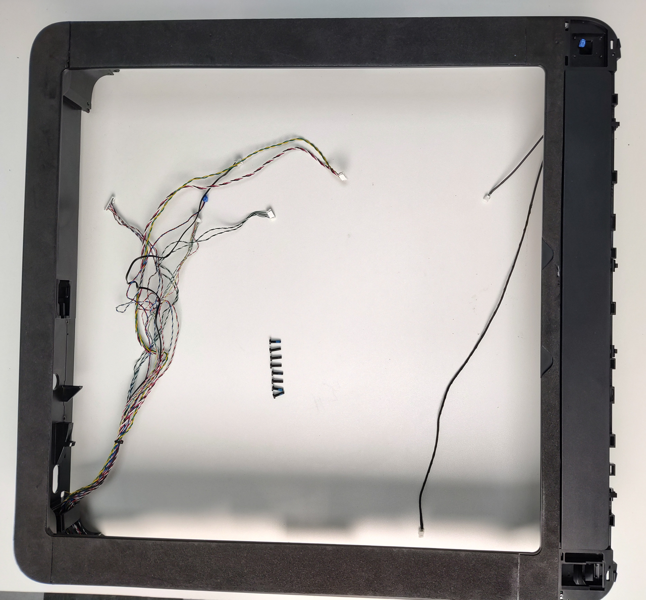
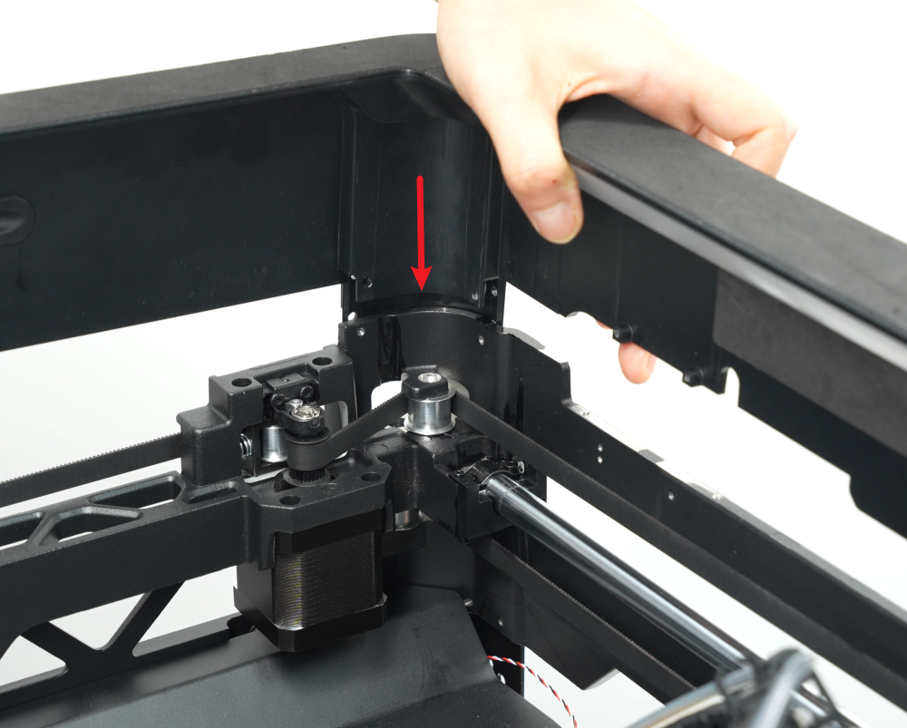
- Refer to the figure below and reinsert the enclosure top frame into the printer frame. Align the cable position to the left rear of the printer. You can use this as a reference for installation;
Note: The front door hall connector is on the inside of the printer and should not be pressed by the enclosure top frame.
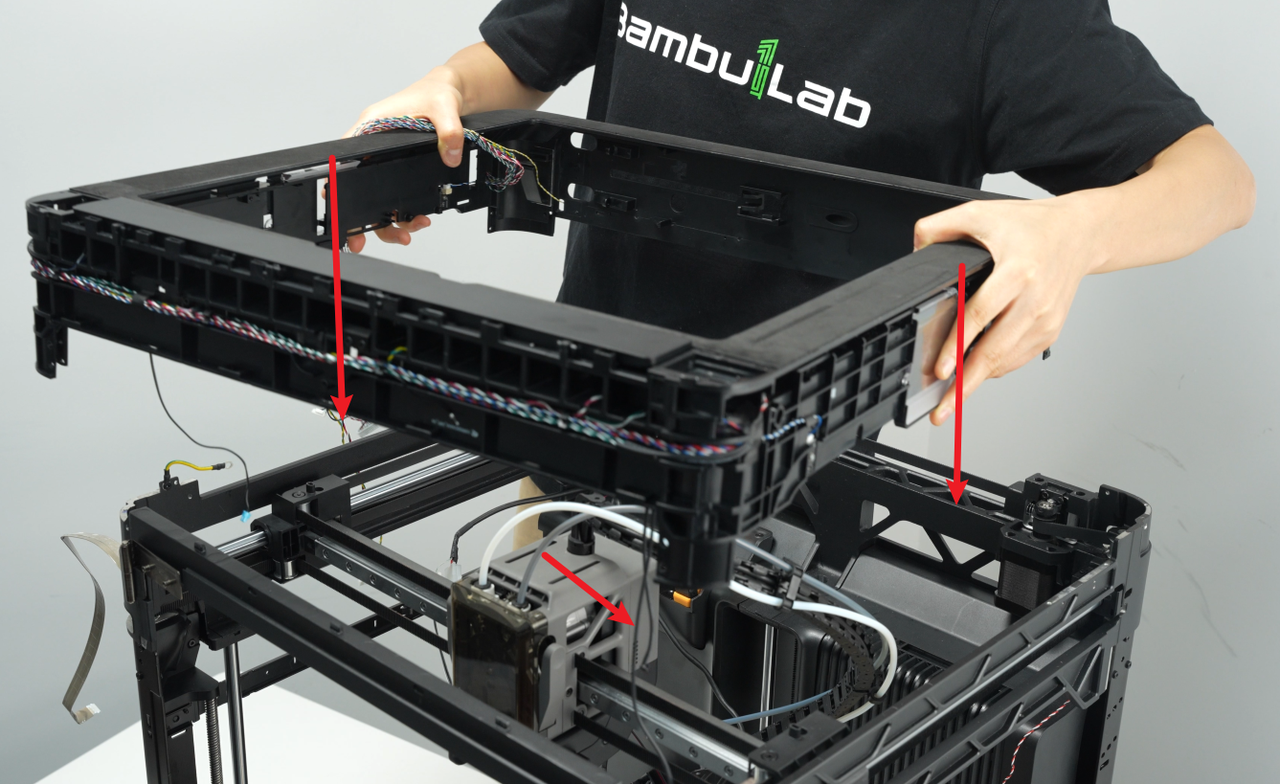
- Use an H2.0 Allen key to install the eight fixing screws (M3x10), two screws for each pillar;


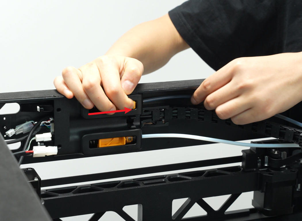
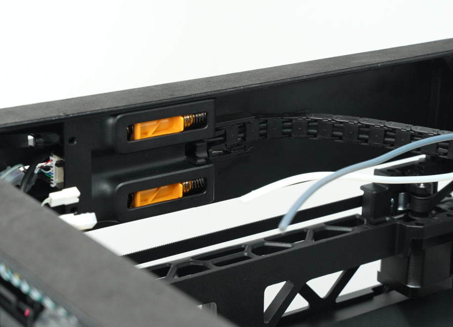
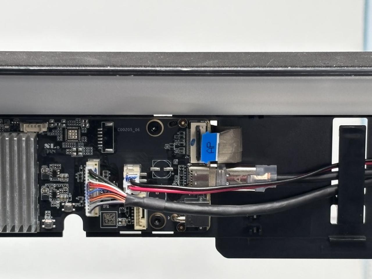
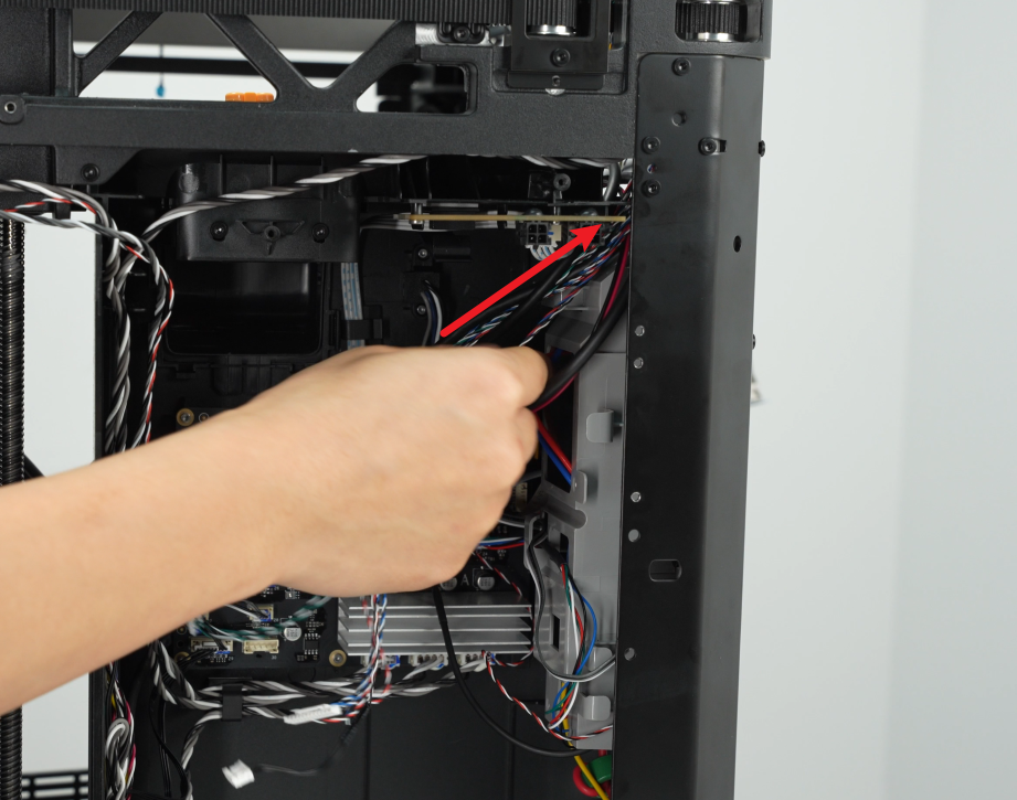
¶ Step 2: Connect the cables
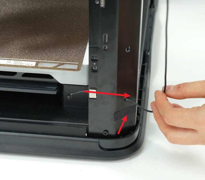
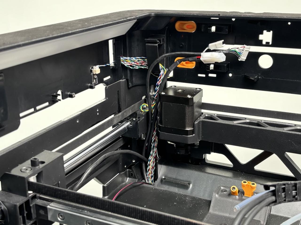
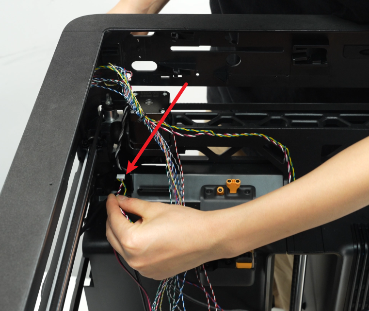
- You can first pass the yellow-green/red-black cables through the small hole on the left inner lining, then pass the cables from the upper left inner side and pull them to the left side of the left inner lining;
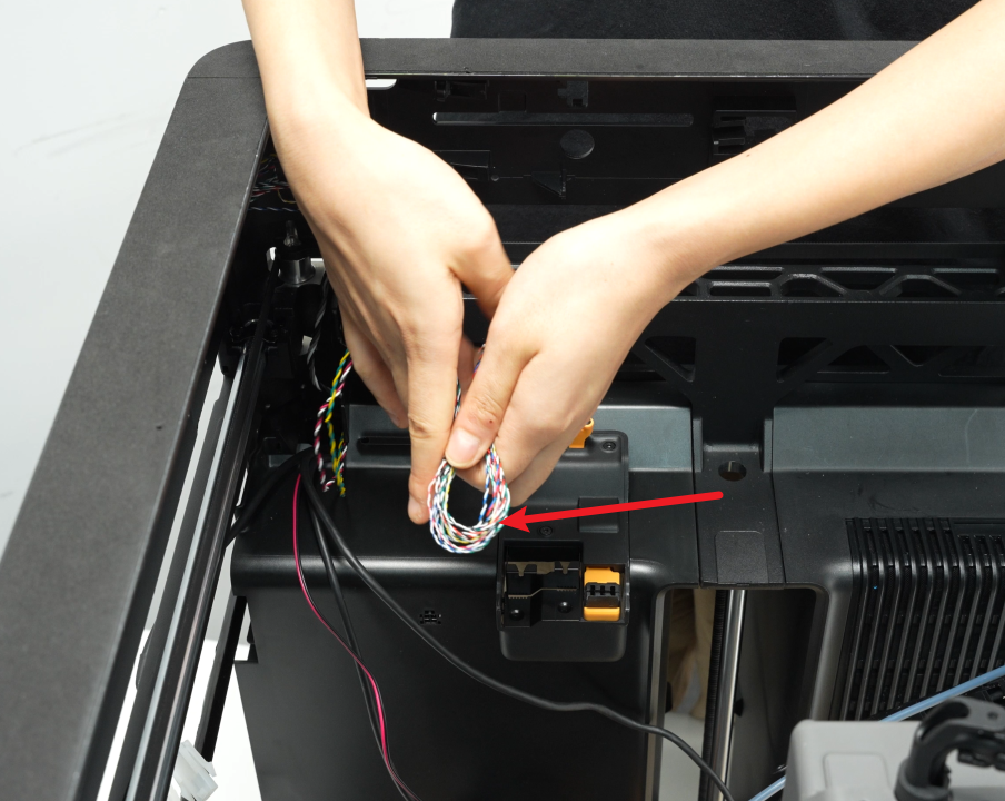
- Fold the remaining cables in half and insert them into the small hole on the left inner lining, then pass these cables through the small hole;
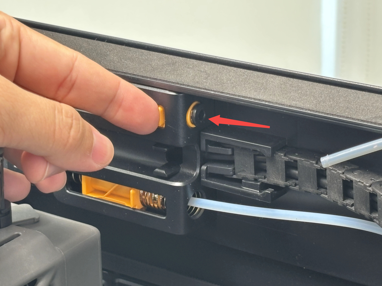
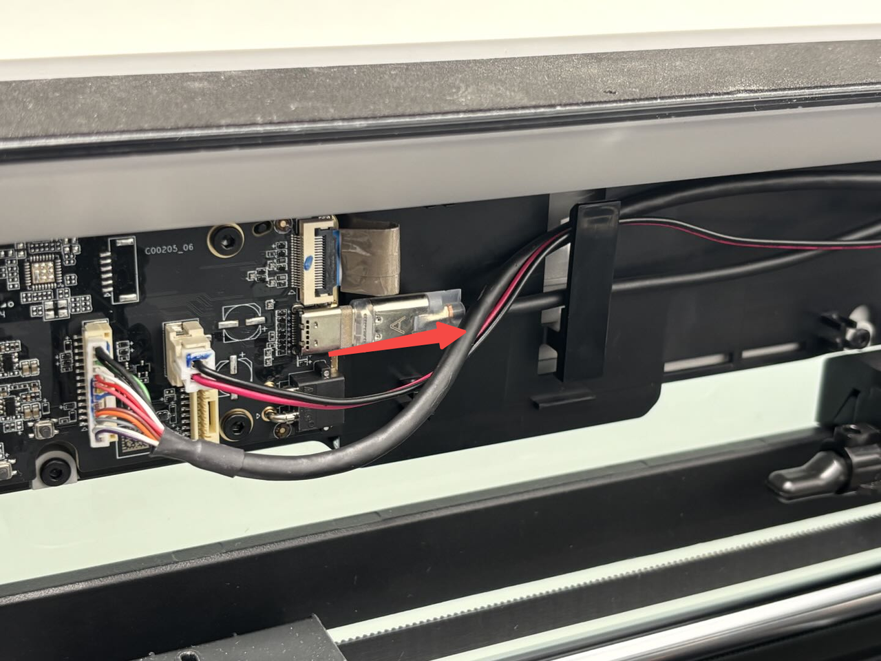
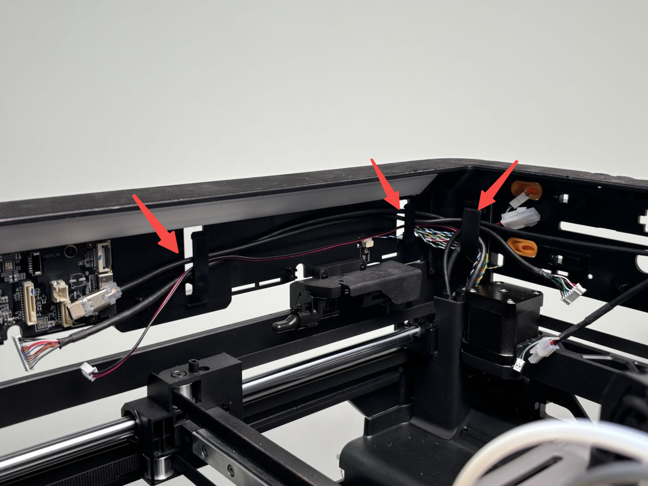
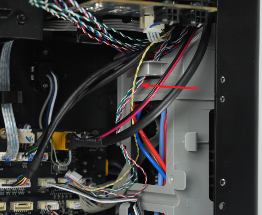
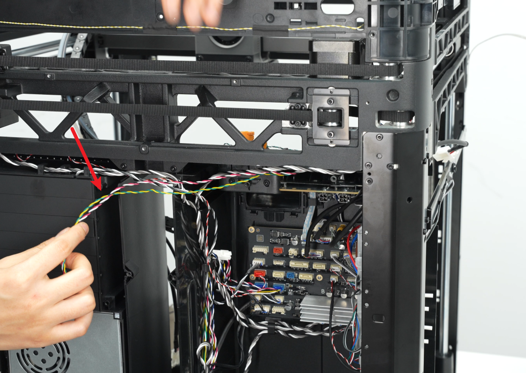
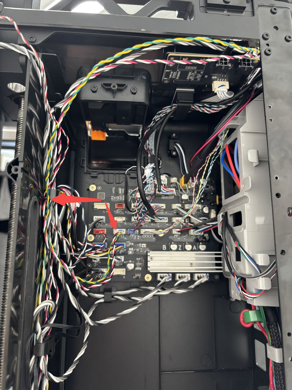
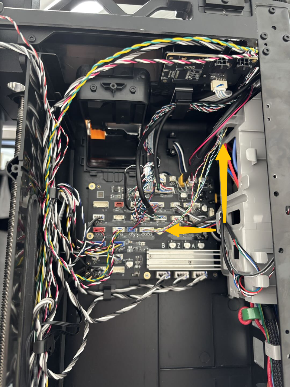
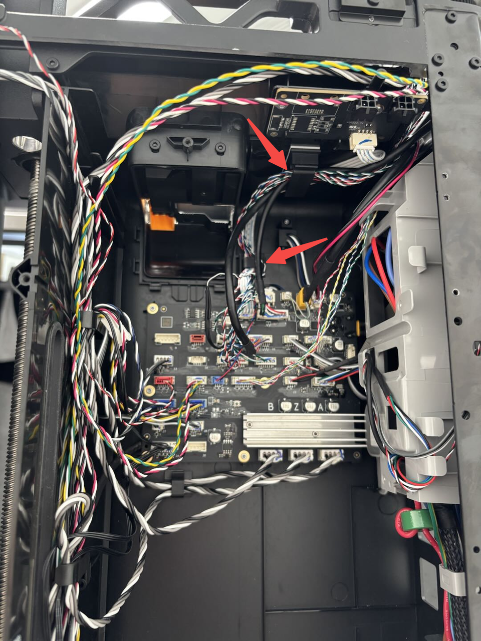
- Refer to the figure below, connect the cables to the MC board in sequence, then buckle the yellow-green/red-black (indicated by the red arrow) cables into the left cable buckle, buckle the yellow-white/blue-white/green-white/red-white cables (indicated by the yellow arrow, sharing the same plug) into the buckle of the AC board cover, and buckle the remaining cables into the two cable buckles on the top of the left lining.
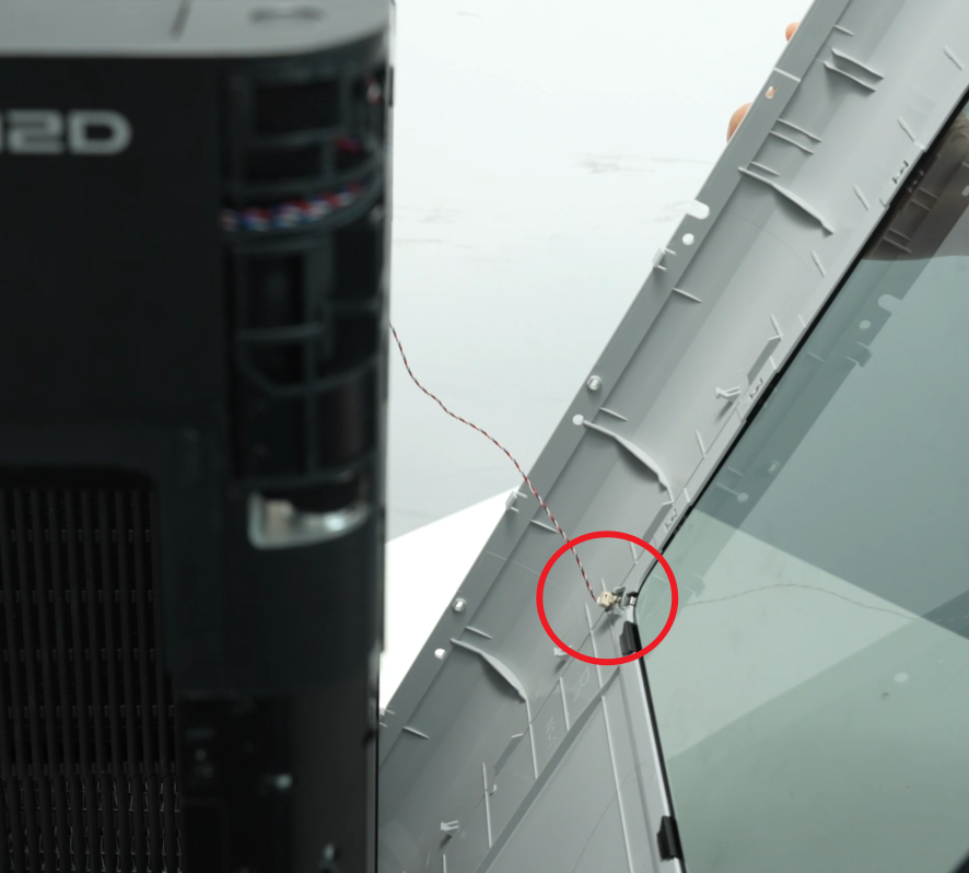
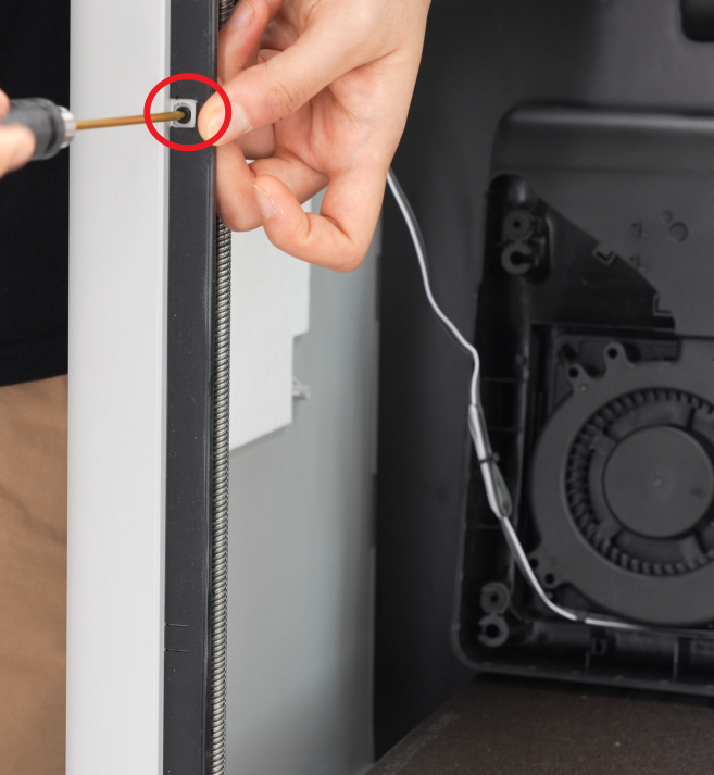
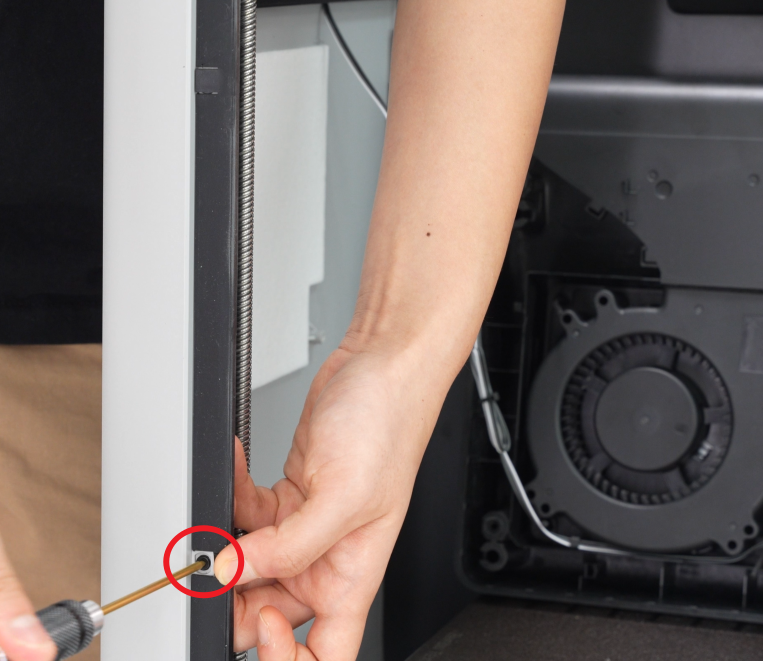
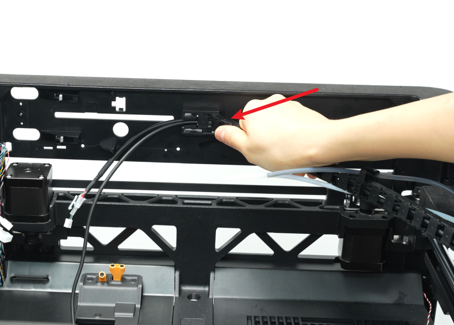
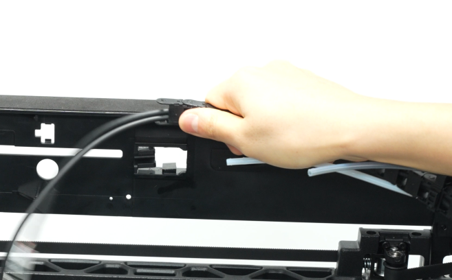
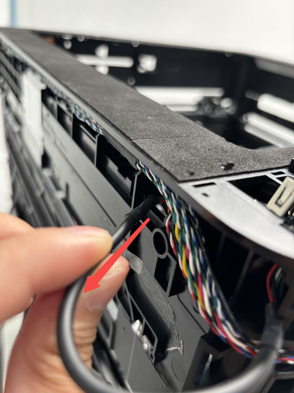
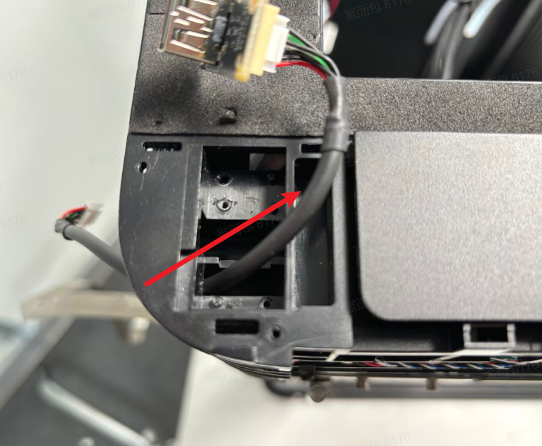
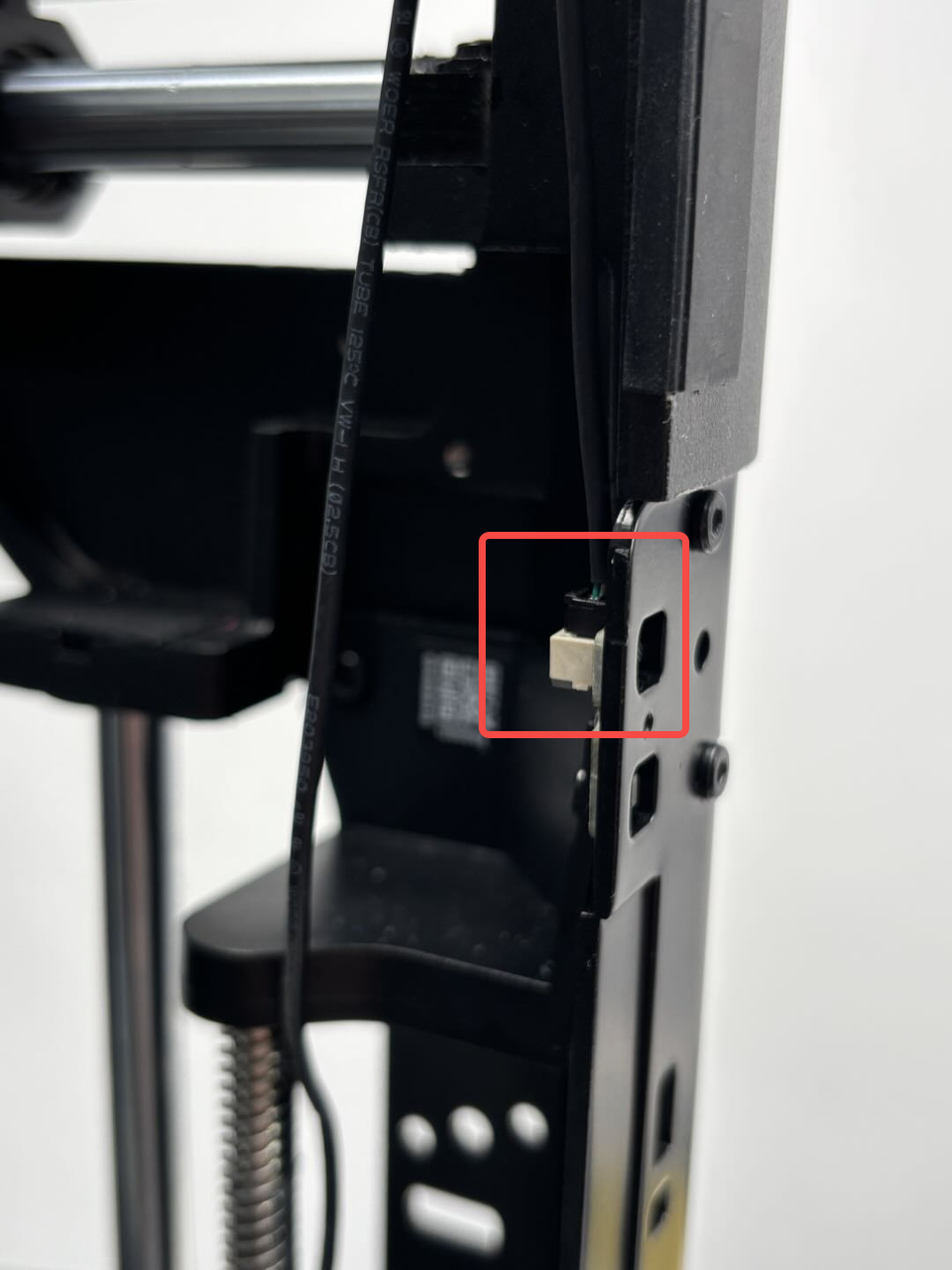
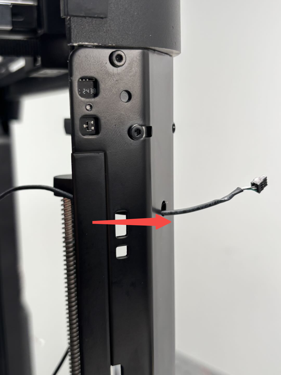
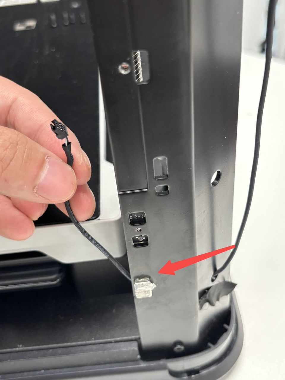
- Connect the hall and hall connector above the front door pillar, pass the hall connector below through the small hole to the outside of the pillar, and then pass it back through the small hole at the bottom to connect with the hall effect sensor, then pull the cable from the outside of the pillar to make the cable slightly tighter to avoid looseness, and then use tape to stick it.
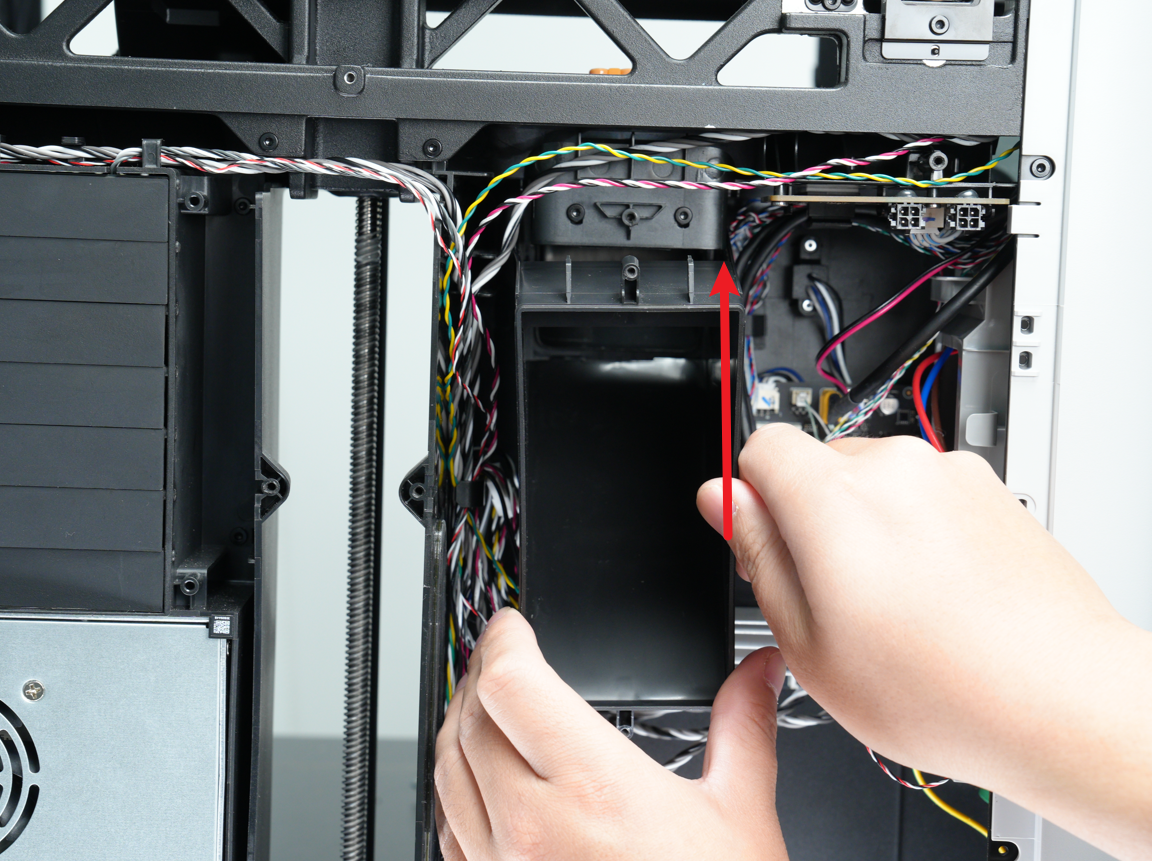
¶ Step 3: Install the purge chute
- Align the two clips at the bottom of the purge chute with the holes in the liner.
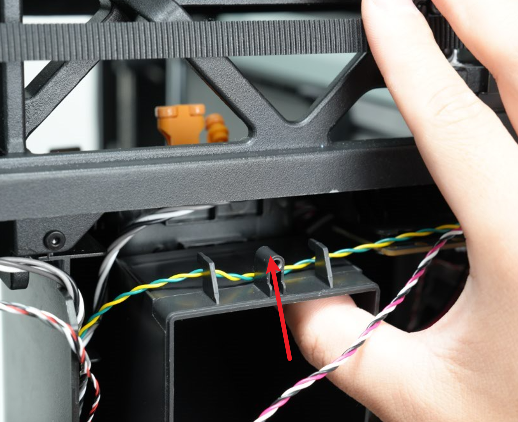
- Then buckle the purge chute upwards, making sure the buckle at the bottom is buckled into the lining, hold the top of the purge chute with your hand, align the screw holes on the top of the purge chute, and finally use an H2.0 Allen key to tighten a fixing screw and buckle the yellow-green and red-white cables behind the cable buckle at the top of the purge chute.

Note: When installing the purge chute, please pay attention to buckling both sides of the purge chute on the outside of the liner. If buckled on the inside, it may not be installed properly.
¶ Step 4: Install the USB port board and Start/Pause button
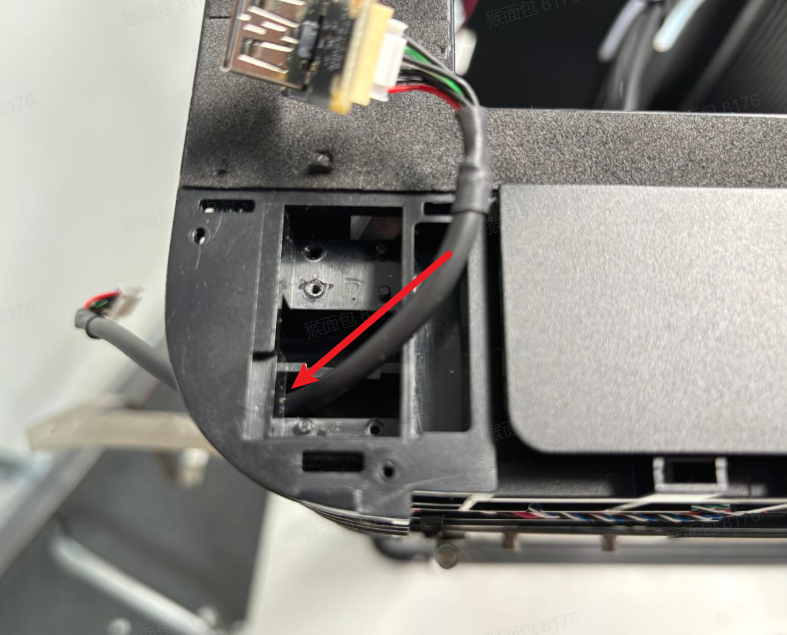
- Pass the cable connected to the USB port board through the top of the upper cover, then pass the cable back through the small hole inside the upper cover, and then use an H1.5 Allen key to tighten the two screws fixing the USB port board;

- Connect the Start/Pause button to the cable, and tighten the two fixing screws (BT2x5) using an H1.5 Allen key.

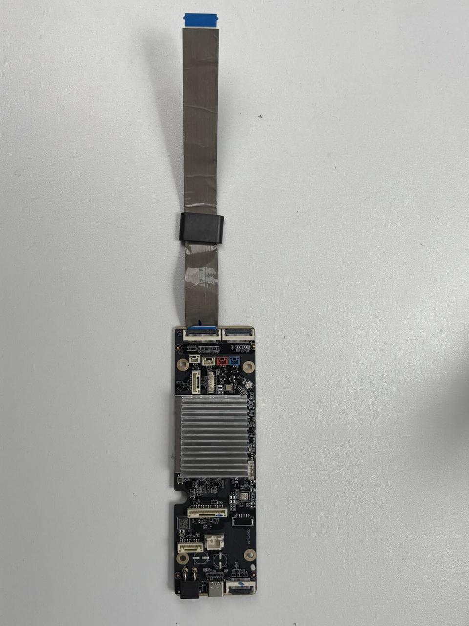
¶ Step 5: Install the AP board
First, pass the screen FPC through the small hole in the upper cover, then use an H2.0 Allen key to tighten the four AP board fixing screws, and then connect the cables as shown in the figure below:
¶ Step 6: Connect the USB-C cable/MC-TH cable/cable chain tail
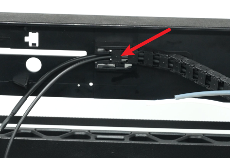
- First, buckle the cable cover into the printer, and then snap the tail of the cable chain into the upper cover;
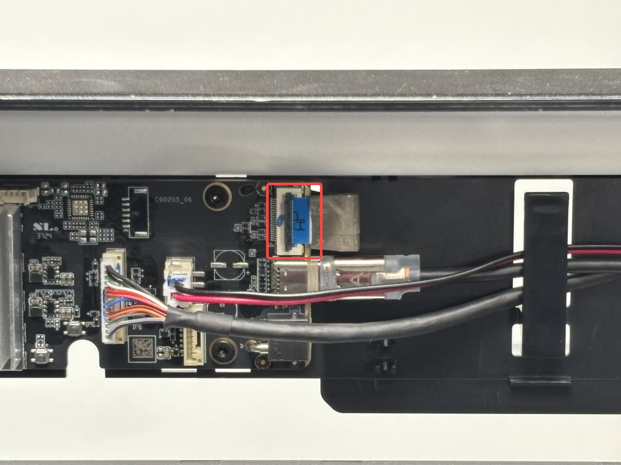
- Reconnect the live view camera cable to the AP board and reattach the FPC to the side of the printer;

- Reconnect the toolhead to MC board cable, and re-insert the USB-C cable and MC-AP cables into the buckle, and then connect them to the AP board.
Note that the side with "A" printed on the USB-C cable should face outwards!
¶ Step 7: Install the filament buffer and AP board cover
- Reconnect the buffer connector to the buffer, and then tighten the four fixing screws (BT3×8) using an H2.0 Allen key, and finally reconnect the two PTFE tubes to the buffer.

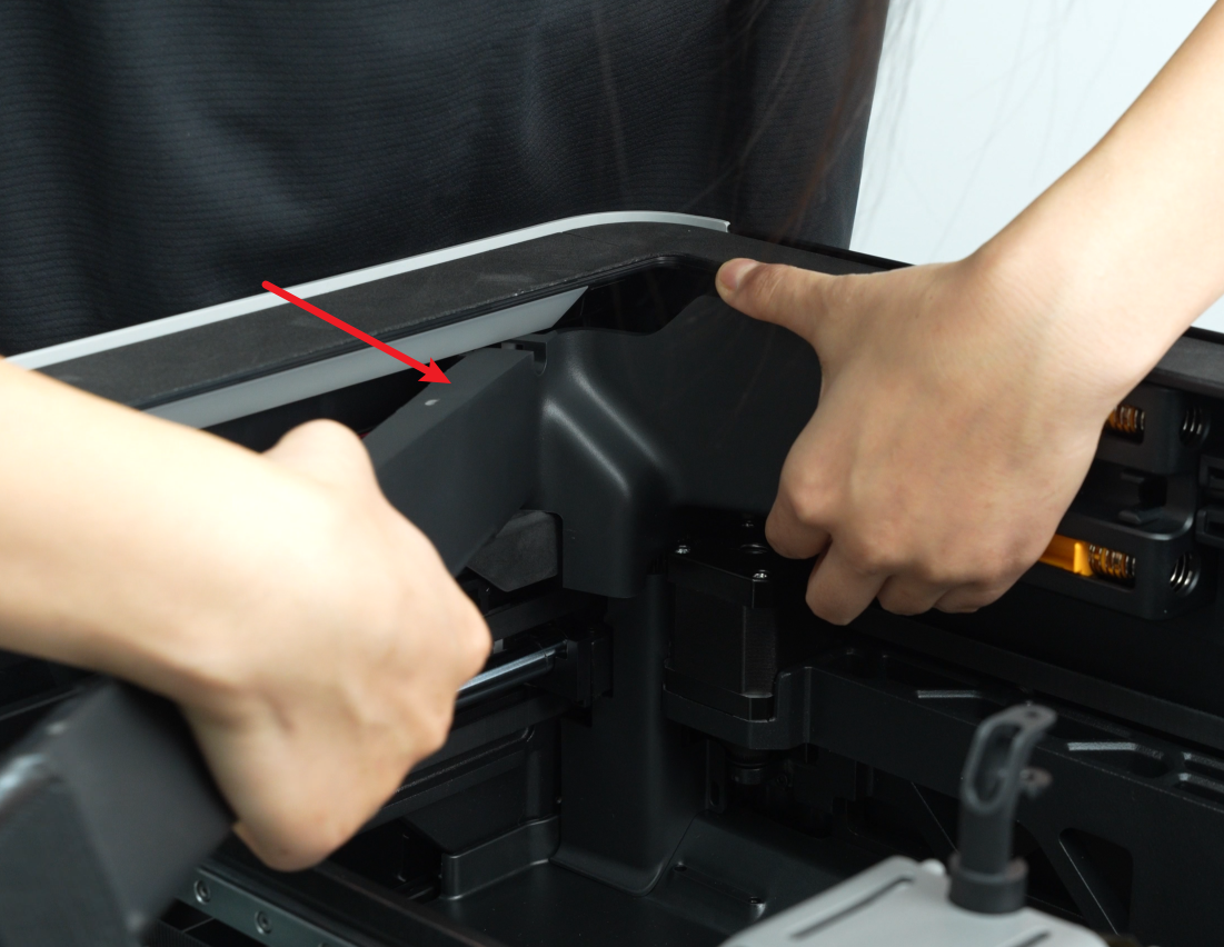
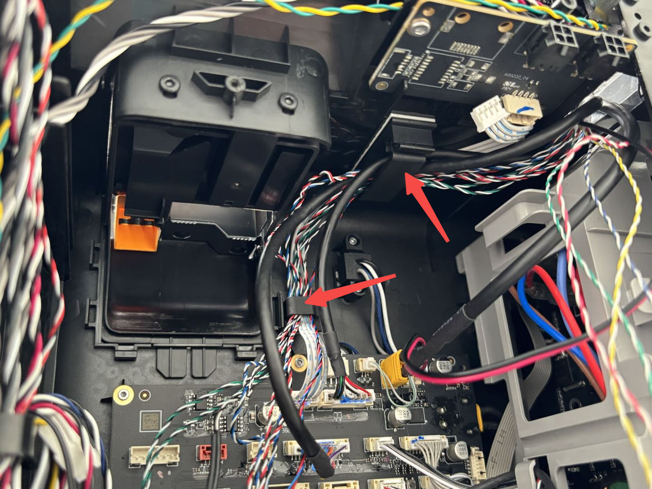
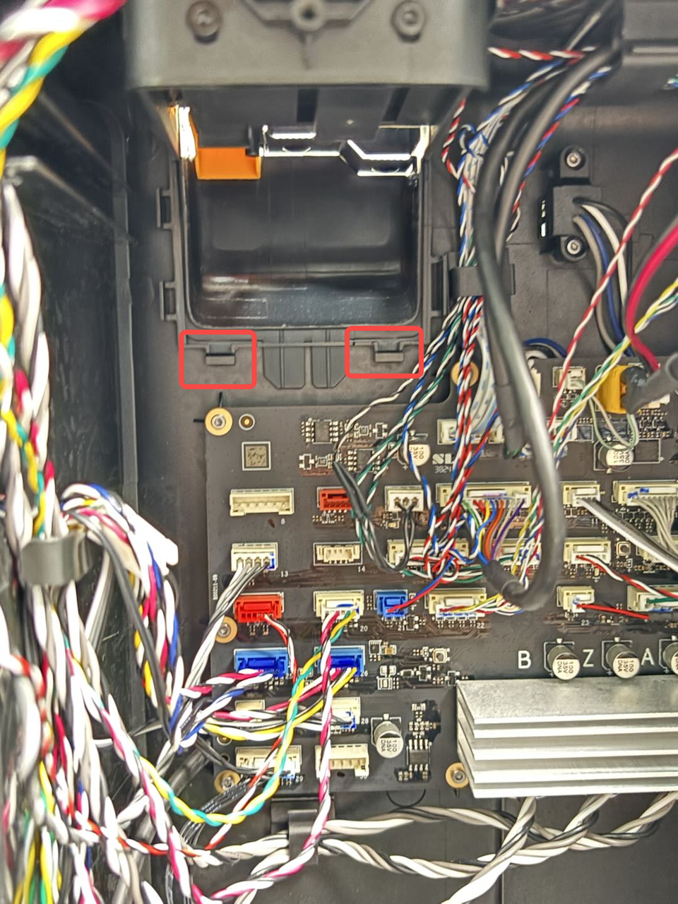
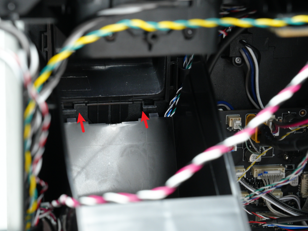
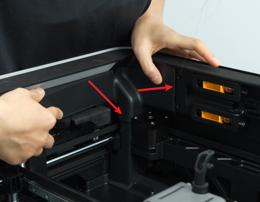
- First, snap the AP board cover back from the side close to the back of the printer, press the two places indicated by the arrows into place, flush with the buffer on the right side and flush with the cable cover on the bottom, and then tighten a fixing screw (BT2.6x8) using an H2.0 Allen key.
¶ Step 8: Install the left/right filament cutter stoppers
Align the filament cutter stoppers with the screw holes on the printer and tighten the four fixing screws using an H2.0 Allen key. (Red circle mark: BT2.6x8; blue box mark: M2.5x5).
Note: The screw holes for the left and right filament cutter stoppers are similar, two in the upper row and two in the lower row.


¶ Step 9: Install the left side panel/front glass door
Since the front glass door is removed together with the steps to remove the left side panel, you can refer to this Wiki to install the left side panel and the front glass door together on the printer:Replace H2D Left/Right Side Panel
¶ Step 10: Install the right side panel
You can refer to this Wiki for detailed steps on how to install the right side panel: Replace H2D Left/Right Side Panel
¶ Step 11: Install the front cover and screen
- Position the left side of the front cover near the printer’s left side. Insert the screen FPC into the connector and fasten the black clasp.
- Hold the right side of the front cover and gently bend it, then insert it into the printer. Press the front cover down to ensure all snaps are secured.
- Finally, use the H1.5 Allen key to tighten one fixing screw (BT2x12).

¶ Step 12: Install the rear panel
You can refer to this Wiki to install the H2D rear panel:Replace H2D Rear Panel
¶ Verify the Functionality
After installing the enclosure top frame, check if it is loose.
Then connect the power supply and turn on the printer, run the self-test, and check if the self-test can be completed successfully.
¶ List of screws used
In the table below, you can find a list of all the screws used by the printer for this section. This list is provided to be of service if some of the screws need to be replaced:
| Specification | Image | Use | Position | Quantity | |
|---|---|---|---|---|---|
| BT3x8 | Used to attach the rear panel | 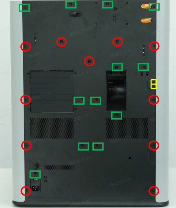 |
12 | ||
| Used to attach right side panel | 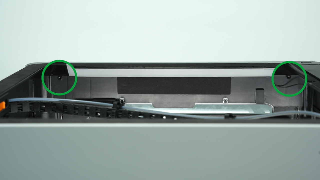 |
2 | |||
| Used to attach the left side panel | 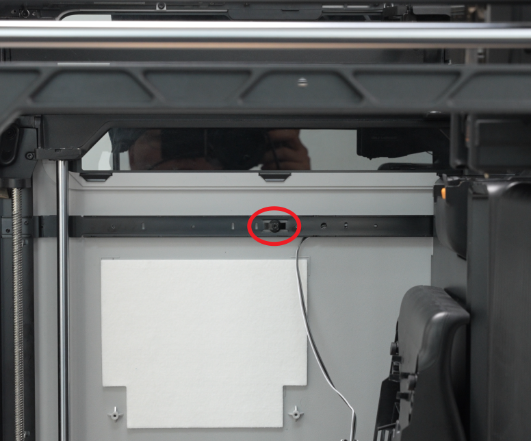 |
 |
3 | ||
| Used to attach the filament buffer | 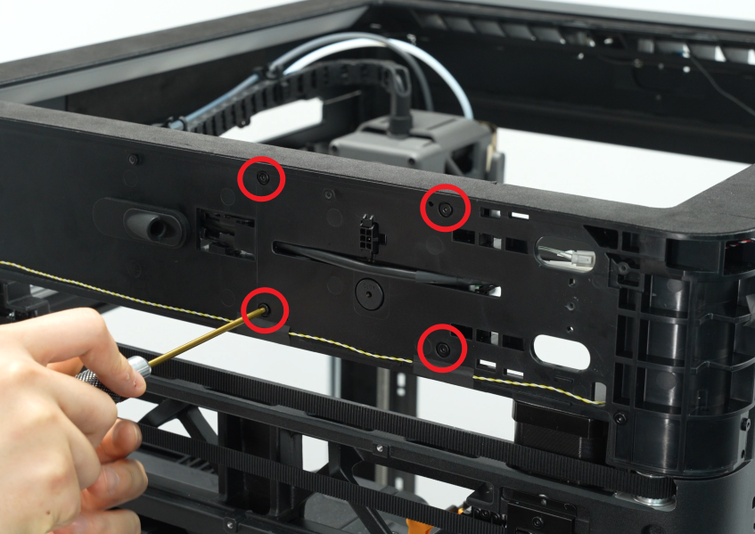 |
4 | |||
| Used to attach the purge chute | 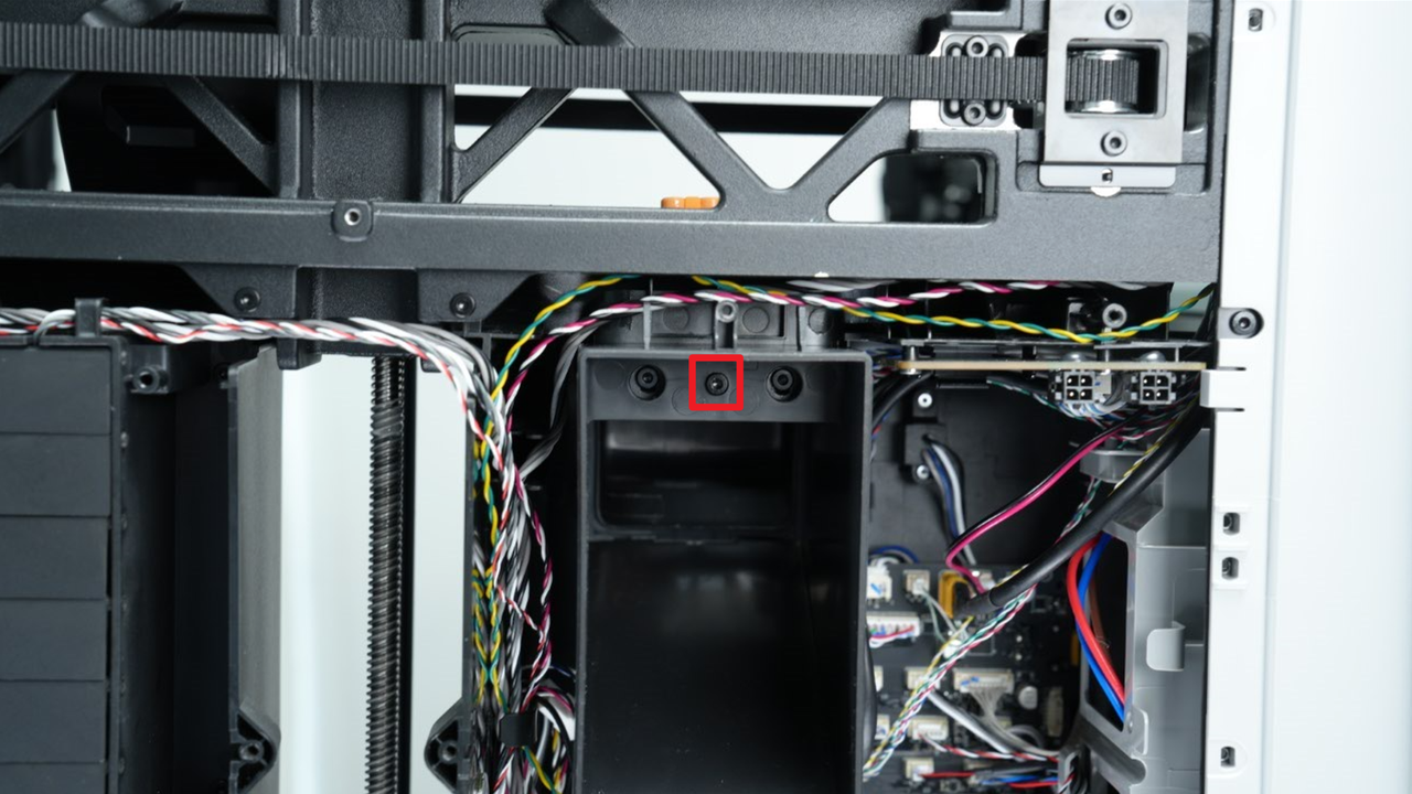 |
1 | |||
| ST3x8 | Used to attach the rear panel |  |
11 | ||
| ST3x12 | Used to attach the spool holder bracket |  |
2 | ||
| ST3x3 | Used to attach the left side panel | 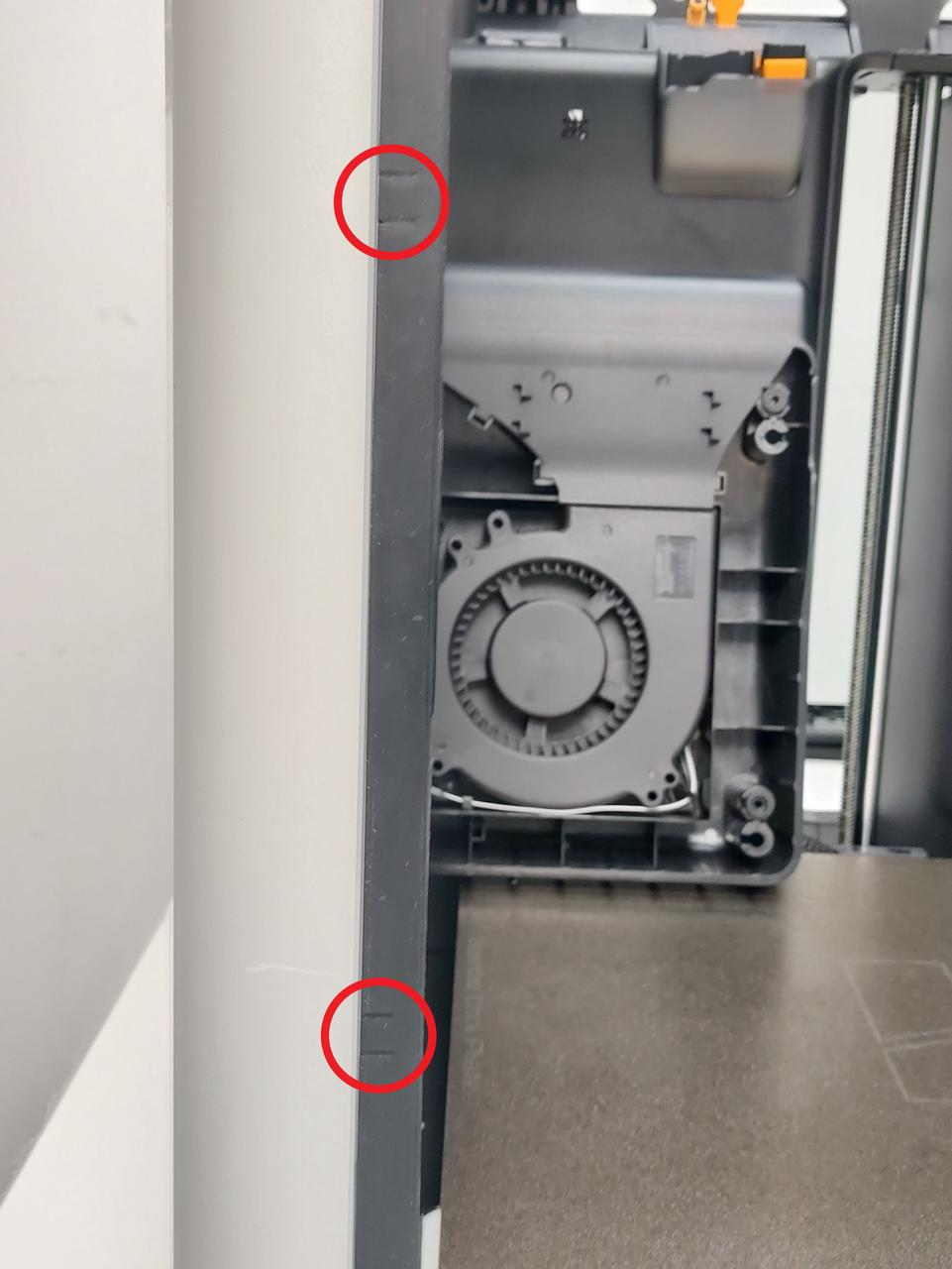 |
2 | ||
| Used to attach the right side panel | 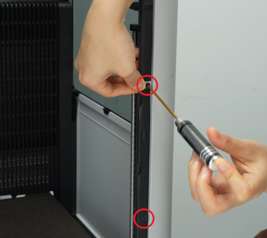 |
2 | |||
| M3x3 (Nut diameter 10mm) | Used to attach the front glass door | 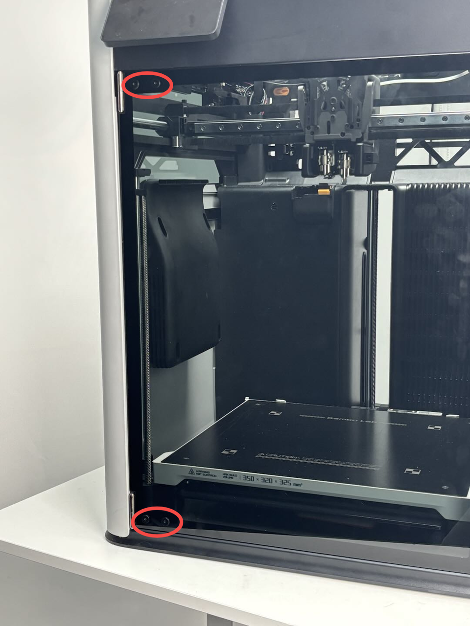 |
4 | ||
| BT2x12 | Used to attach the front cover | 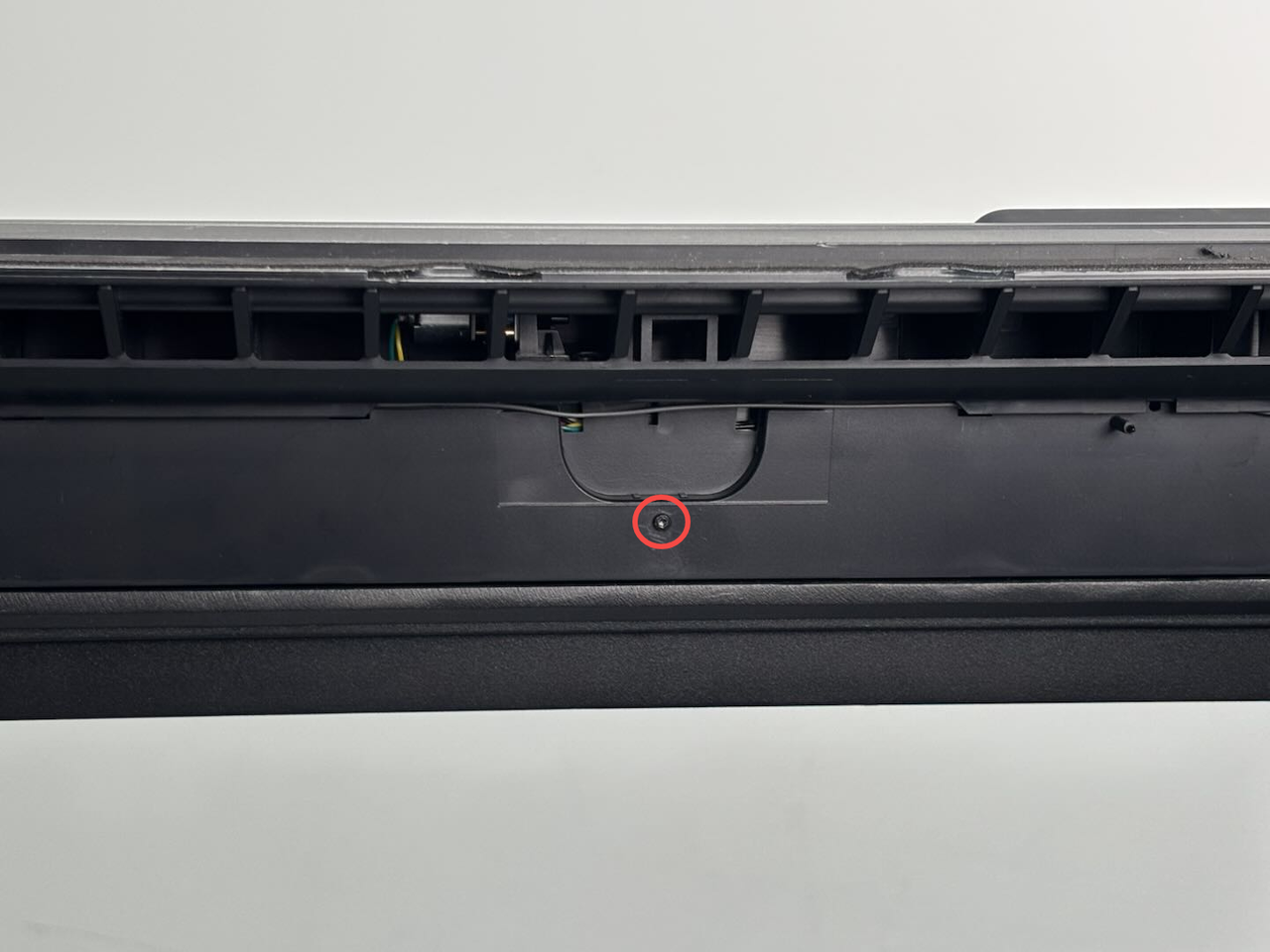 |
1 | ||
| M2x5 | Used to attach the left/right filament cuter stopper (marked with blue square) |  |
 |
4 (2 pieces for each left/right filament cuter stopper, 4 pieces in total) | |
| BT2x6 | Used to attach the left/right filament cuter stopper (marked with red circle) |  |
 |
4 (2 pieces for each left/right filament cuter stopper, 4 pieces in total) | |
| BT2.6x8 | Used to attach the AP board cover | 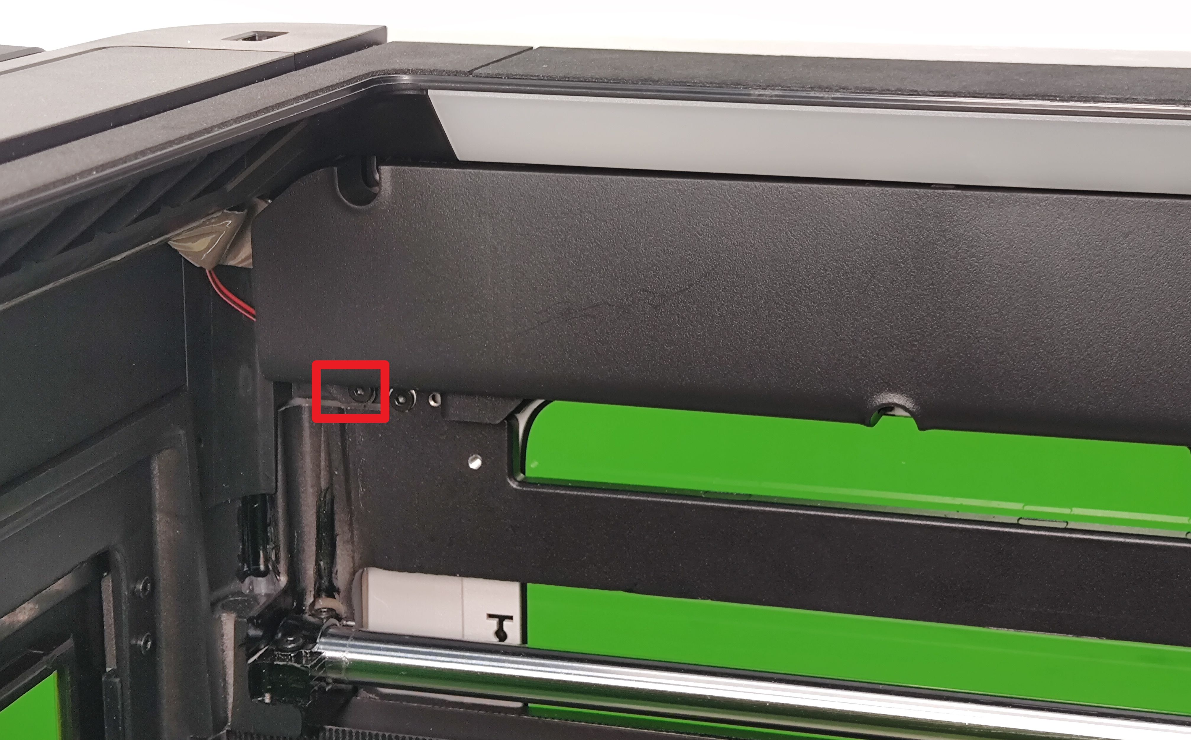 |
1 | ||
| BT3x5 | Used to attach the AP board | 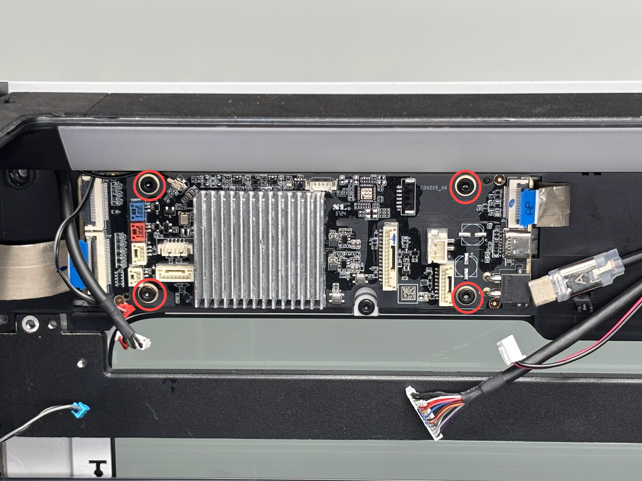 |
4 | ||
| BT2x5 | Used to attach the USB interface board |  |
2 | ||
| Used to attach the start/pause button |  |
2 | |||
| M3x10 | Used to attach the enclosure top frame | 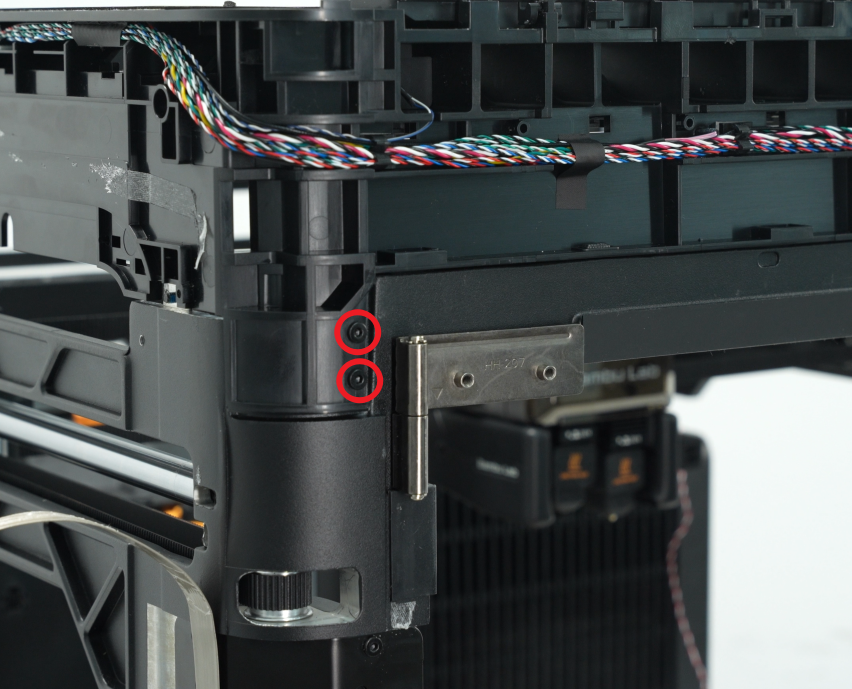 |
 |
8 | |
 |
 |
¶ End Notes
We hope the detailed guide provided has been helpful and informative.
If this guide does not solve your problem, please submit a technical ticket, we will answer your questions and provide assistance.
If you have any suggestions or feedback on this Wiki, please leave a message in the comment area. Thank you for your support and attention!