¶ Kit Contents
For H2 series, including H2D and H2S, the z-axis lead kit includes:
- M3×5 screws × 12
- M3×6 screws (blue-threadlocker screws) × 9
- M3×6 screws (mixed red-threadlocker screws and blue-threadlocker screws) × 2
- Top fixing block × 1
- lead screw assemblies × 3
- Lead screw nut × 3 (pre-installed on the lead screw at factory)
¶ Compatible Models
H2 series, including H2D and H2S
¶ When to Replace
Lead screw is bent or warped
Lead-screw nut is worn
¶ Tools Require
- H2.0 L-shaped hex key
- H2.0 straight hex driver
- H1.5 straight hex driver
- Flathead screwdriver
¶ Location Overview
There are three Z-axis lead screws on the H2 series: the left and right pair near the front door posts share the same removal and installation method; the rear lead screw is partially covered by the inner liner and requires removing the rear panel first.
It's crucial to power off the printer before conducting any maintenance work, including work on the printer's electronics and tool head wires. Performing tasks with the printer on can result in a short circuit, leading to electronic damage and safety hazards.
During maintenance or troubleshooting, you may need to disassemble parts, including the hotend. This exposes wires and electrical components that could short circuit if they contact each other, other metal, or electronic components while the printer is still on. This can result in damage to the printer's electronics and additional issues.
Therefore, it's crucial to turn off the printer and disconnect it from the power source before conducting any maintenance. This prevents short circuits or damage to the printer's electronics, ensuring safe and effective maintenance. For any concerns or questions about following this guide, open a new ticket in our Support Page and we will do our best to respond promptly and provide the assistance you need.
¶ Preparation Before You Start
¶ Step 1. Clear the workspace
Remove items around the printer so nothing blocks access or can fall into the machine during service.
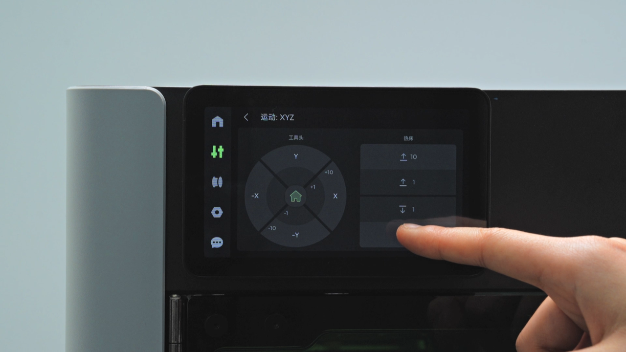
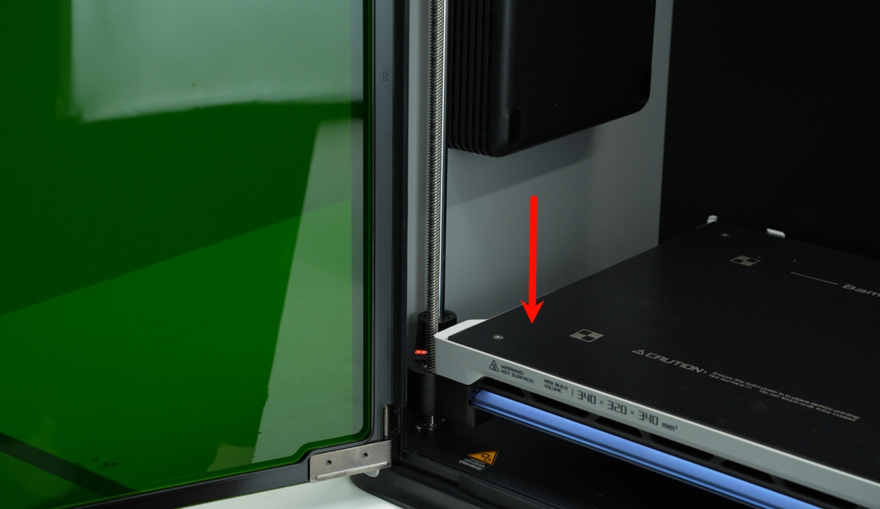
¶ Step 2. Lower the heatbed
Move the heatbed to the lowest position to create working clearance and avoid interferences.
 |
 |
¶ Step 3. Lock the heatbed
Using an H2.0 straight-handle hex key, tighten the four Z-axis slider fixing screws (M3×35×8) to lock the heatbed firmly in place, preventing vertical movement during subsequent operations and avoiding lead screw bending from sliding impacts.
 |
 |
 |
|---|
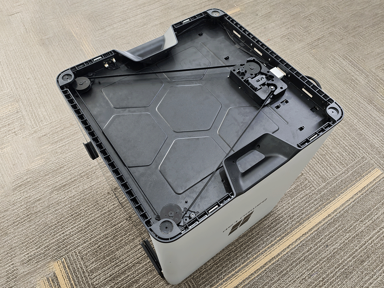
¶ Step 4. Lay the printer down
Carefully place the machine on its back so the bottom panel faces up, which will make subsequent disassembly easier.
Note: To make filming easier, certain steps are not shown in this placement.
¶ Remove the Enclosure Plastic Bottom Ring
¶ Step 1. Remove Handle of the Bottom Ring and Screws
Use an H2.0 straight hex driver to remove the four M3×6 screws at the handle (marked with red squares), then use the H2.0 straight hex driver to remove the six BT2×5 screws on the sides (marked with green circles).
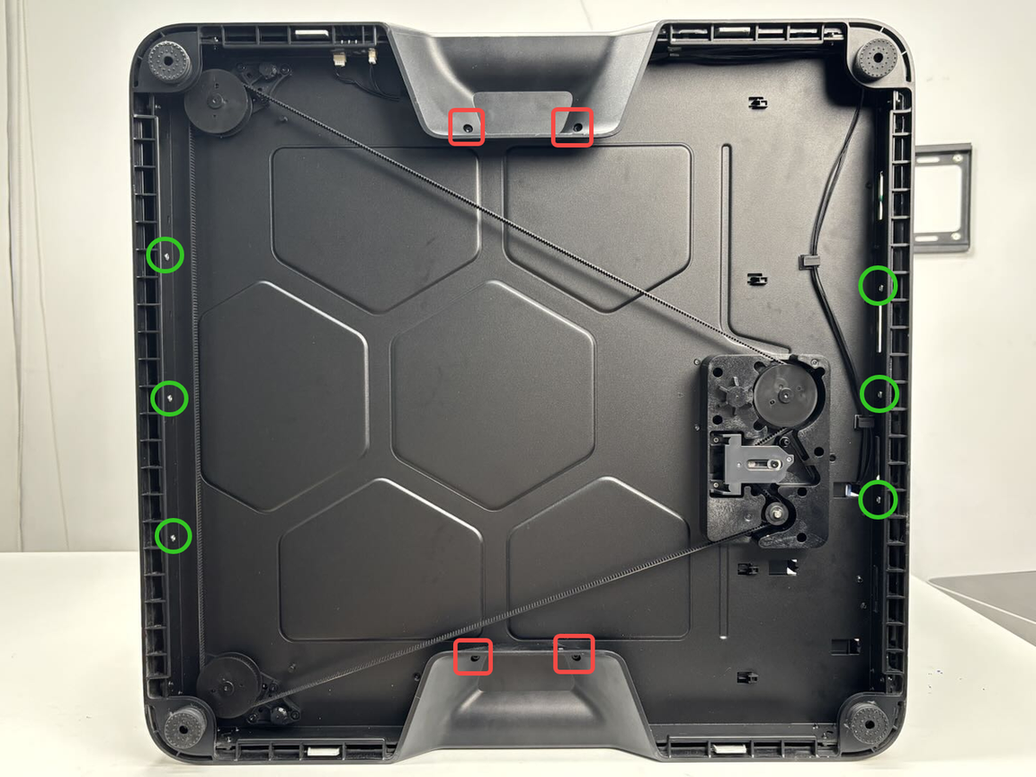
Note: Two of the BT2×5 screws are blocked by the Z-axis tensioner. Use the short end of an H2.0 L-key to crack them loose; if you have a short H2.0 bit, loosen with the short end first, then switch to the bit to remove them fully.
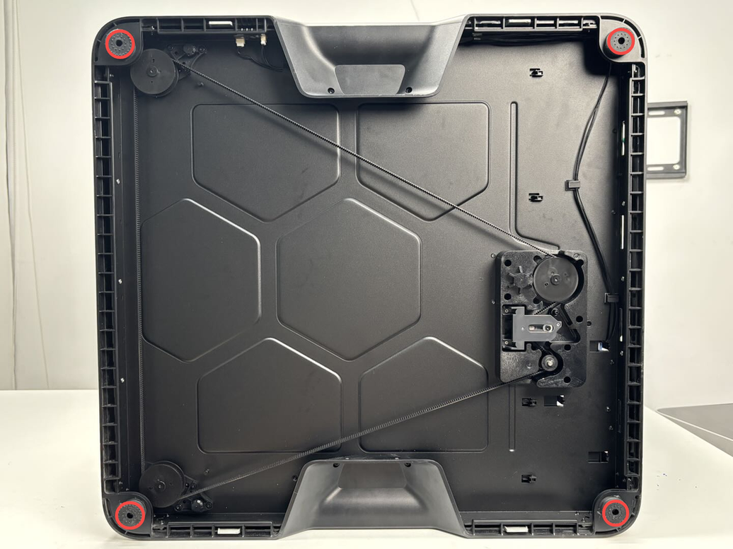
¶ Step 2. Remove the Screws of Printer Feet
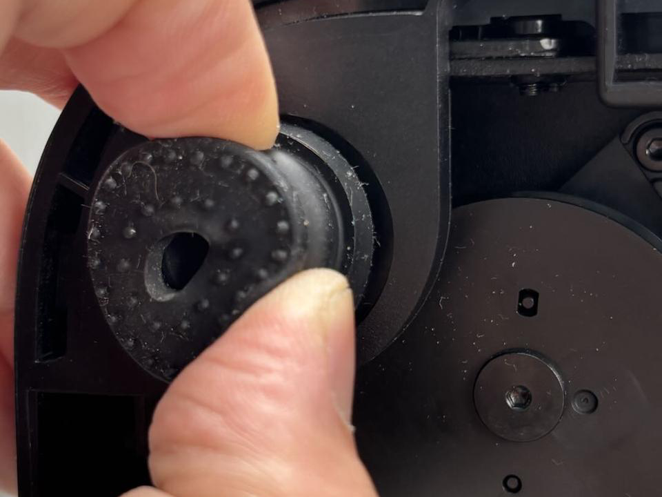
Use an H2.0 straight hex driver to remove the four M3×21.5×6 screws that clamp the printer feet. Remove the printer feet, screws, and washers together and store them safely.
Note: In addition to screws, the printer feet are stuck to the ring with adhesive. After removing the screws, peel the footpads off.
¶ Step 3. Remove the Enclosure Plastic Bottom Ring
To remove the enclosure plastic bottom ring, please pull that the handle area to partially slide it out,then pull at the left/right footpad areas to fully extract it. For more detail, you can see Replace H2D Enclosure Plastic Bottom Ring。
¶ Replace the Front Z-Axis Lead Screws (Left/Right are the Same)
¶ Remove the front Z-axis lead screw
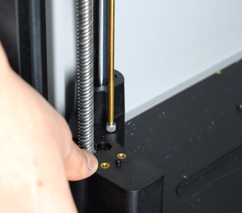
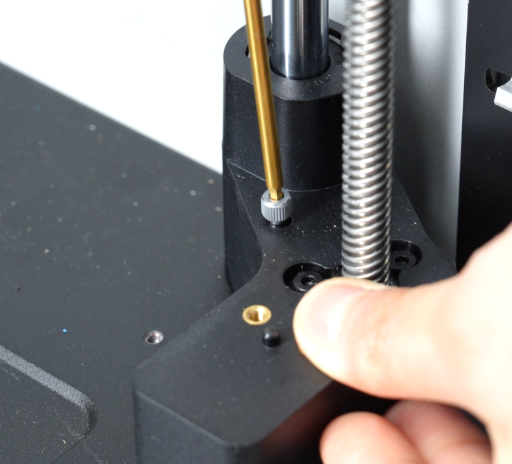
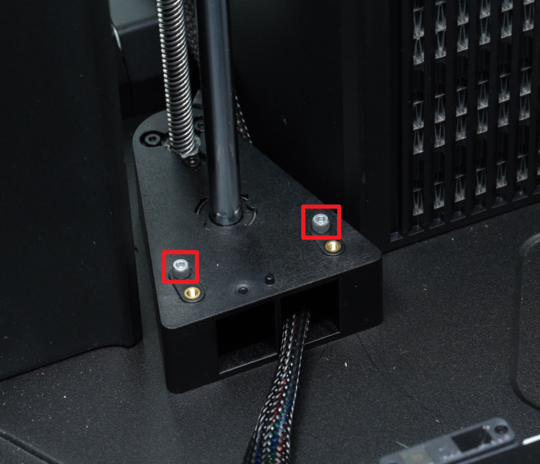
¶ Step 1. Remove the bottom lead-screw mounting screws
Using an H2.0 straight hex driver, remove the bottom mounting screws for the specific Z-axis lead screw you’re replacing.
Note: Each of the left and right Z-axis lead screws has four mounting screws at bottom.
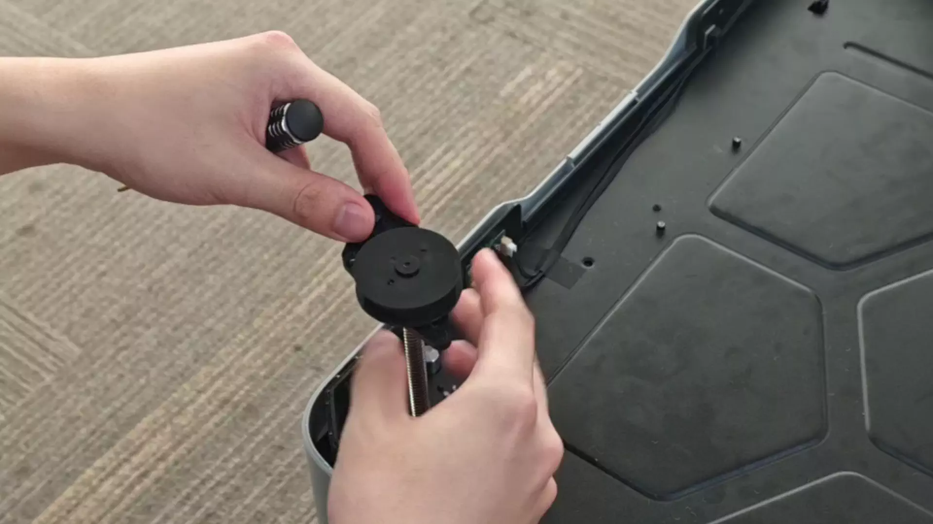
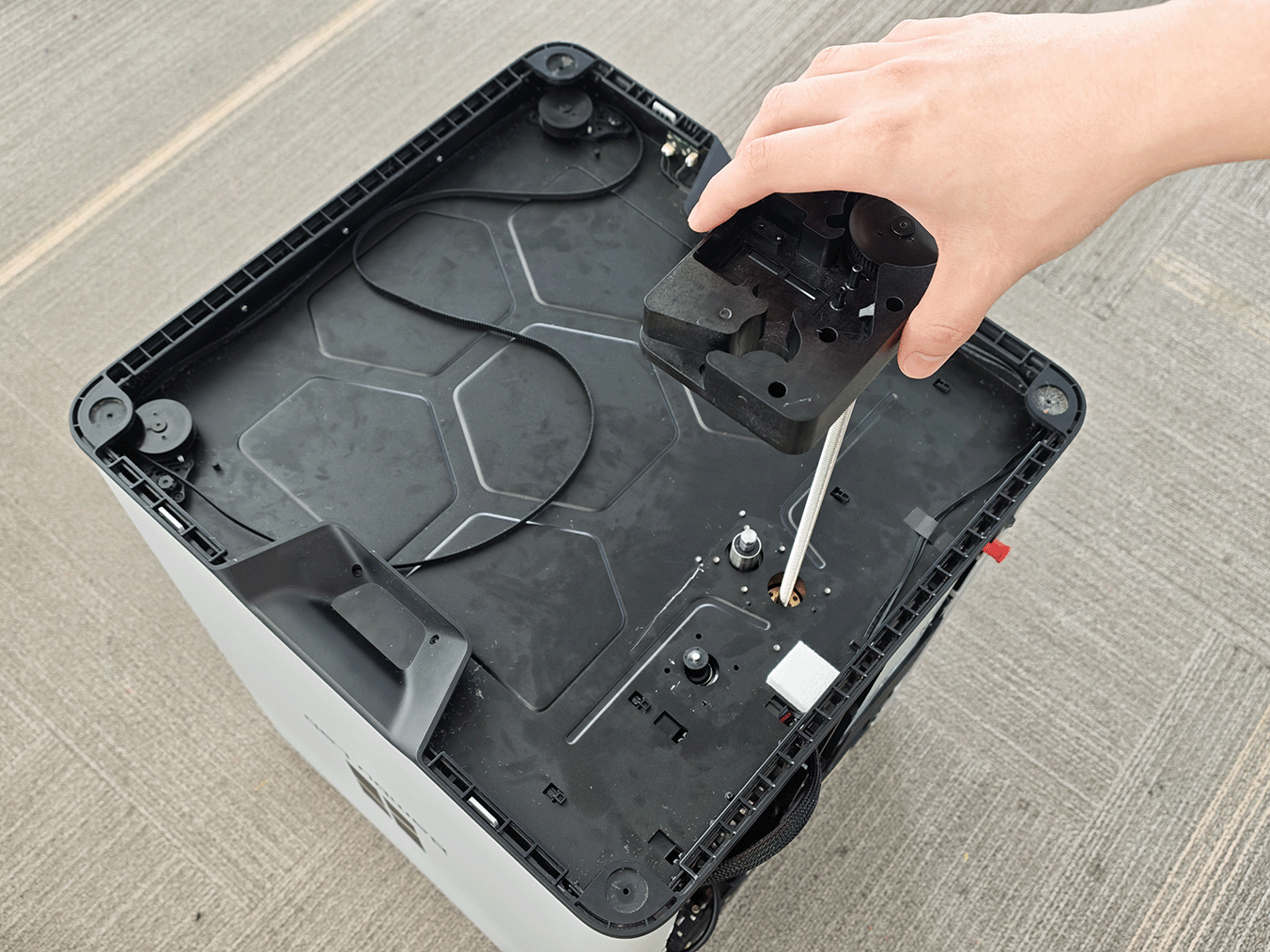
¶ Step 2. Remove the Z-axis lead screw
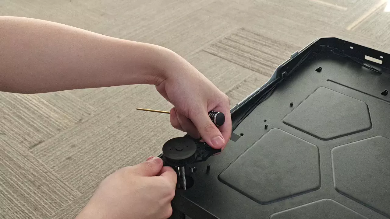
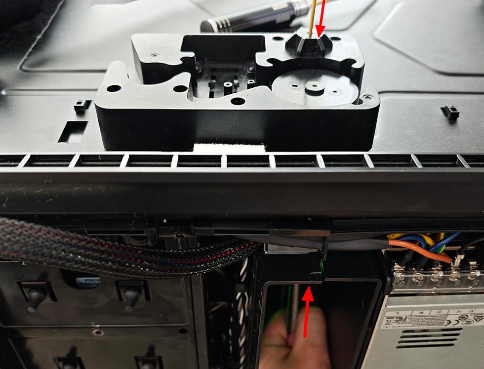
Because the guide shaft is an interference fit, pulling the lead screw straight up can lift the guide shaft and its top adhesive dot out together. Two people are recommended for this step:
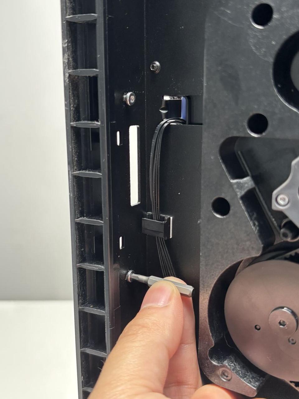
-
Person 1: From the bottom through-hole of the guide rod, lightly brace the end of the rod with a screwdriver to keep it from lifting.
-
Person 2: From inside the chamber, hold the lead screw firmly and push upward to gradually separate the lead-screw base from the guide rod.
Once the lead-screw base lifts slightly and you hear a faint “click” (the normal sound of the locating faces releasing), and you can feel a small gap open between the guide rod and its support, start withdrawing the lead screw so it gradually disengages from the lead-screw nut. Maintain a slow, steady rotation until the lead screw is fully removed.
¶ Optional: Removing the lead-screw nut (only if replacing or damaged)
If the lead-screw nut isn’t damaged, we don’t recommend removing or replacing it on its own. If you must, proceed:
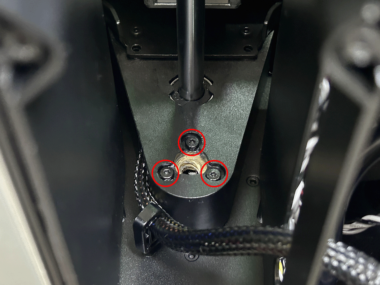
- After removing the lead screw, please locate the lead screw nut (location shown below).
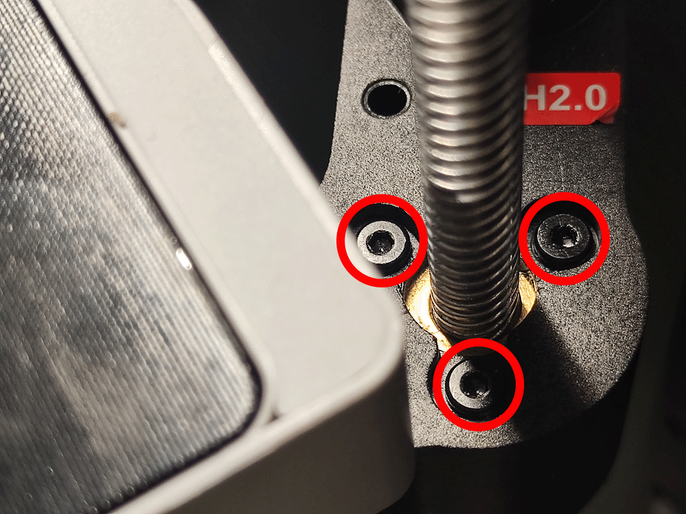
- Using an H2.0 L-shaped hex key to loosen the screws with small turns in the tight space. Each top lead-screw nut (left/right) has three fixing screws.
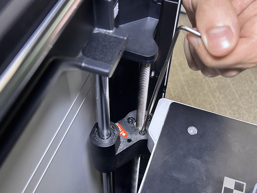
Note: These top screws use the red-threadlocker screws. The first removal may require extra torque to break the threadlocker. Keep the driver seated to avoid cam-out or slipping that could scratch parts.
¶ Install the front Z-axis lead screw
¶ Optional: Pre-install the lead-screw nut to the heatbed locating hole (only if replacing or damaged)
To avoid fixing the nut to the lead screw first—making later alignment between the bed and lead screw difficult—we recommend pre-installing the nut into the heatbed locating hole. This step is for positioning only, not final tightening.
Note: If you fully tighten the lead-screw nut at this stage, any misalignment can load the lead screw unevenly during assembly and may bend it.
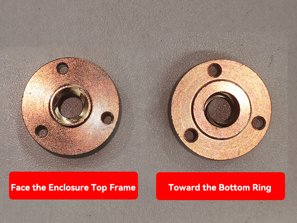
- Confirm the lead-screw nut orientation as shown below.
-
Place the lead-screw nut into the heatbed locating hole.
-
Use the red-threadlocker screws to tack it in place. Do not fully tighten yet, so you can fine-tune later.
-
Centering: ensure the lead-screw nut’s bore is concentric with the heatbed passthrough hole for the lead screw, so the screw will pass without rubbing.
¶ Step 1. Install the Lead Screw
Feed the lead screw downward through the reserved opening at the bottom of the printer. Slowly adjust the angle to align it with the through-hole of the pre-installed nut on the heatbed. Once aligned, thread it in slowly until you feel noticeable resistance and the locating face just makes light contact; stop applying force.
¶ Step 2. Fasten the Bottom Lead-screw Seat
-
While holding the lead screw in place, install the lower fixing screws for this front Z-axis lead screw from the bottom using the H2.0 straight hex driver.
-
If you replaced the lead-screw nut, again verify the lead-screw nut’s bore is perfectly concentric with the bed passthrough hole. Once aligned, tighten the three nut-fixing screws in sequence.
¶ Replace the Rear Z-axis Lead Screw
¶ Remove the Rear Z-axis Lead Screw
¶ Step 1. Remove the Rear Panel
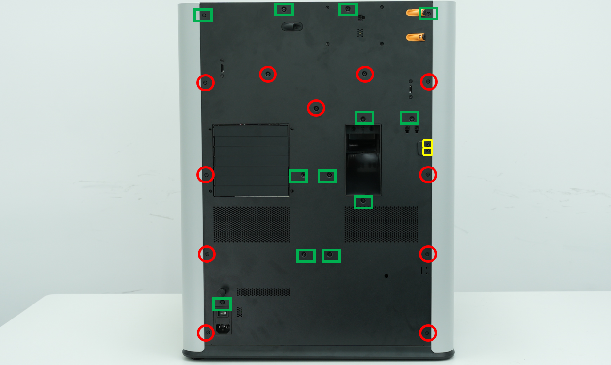
Remove 11 sheet-metal self-tapping screws (ST3×6) and 12 plastic self-tapping screws (BT3×8).
It is strongly recommended to prepare two small containers in advance to separate the two screw types and avoid mix-ups.
-
Use an H2.0 straight hex driver to remove the 11 × ST3×6 (red circles in the below image).
-
Use an H2.0 straight hex driver to remove the 12 × BT3×8 (green rectangles in the below image).
-
The yellow marker indicates the fixing screws for external spool (M3×12).
- Press the pneumatic fitting to clear interference, then tilt the rear panel back slightly and lift it out.
¶ Step 2. Remove the lead screw
-
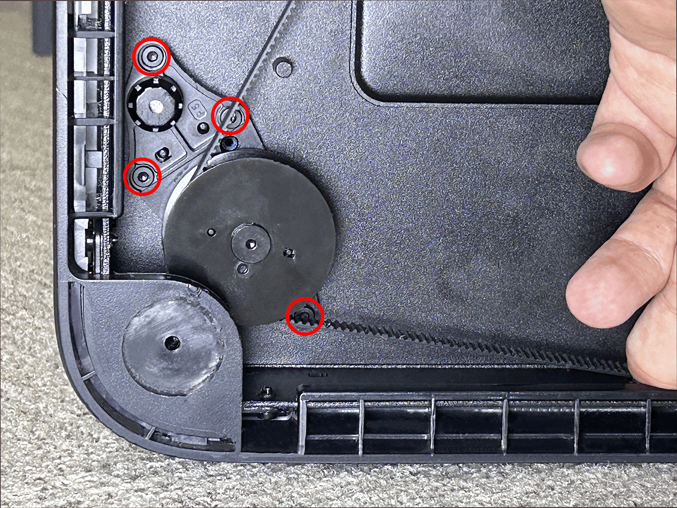
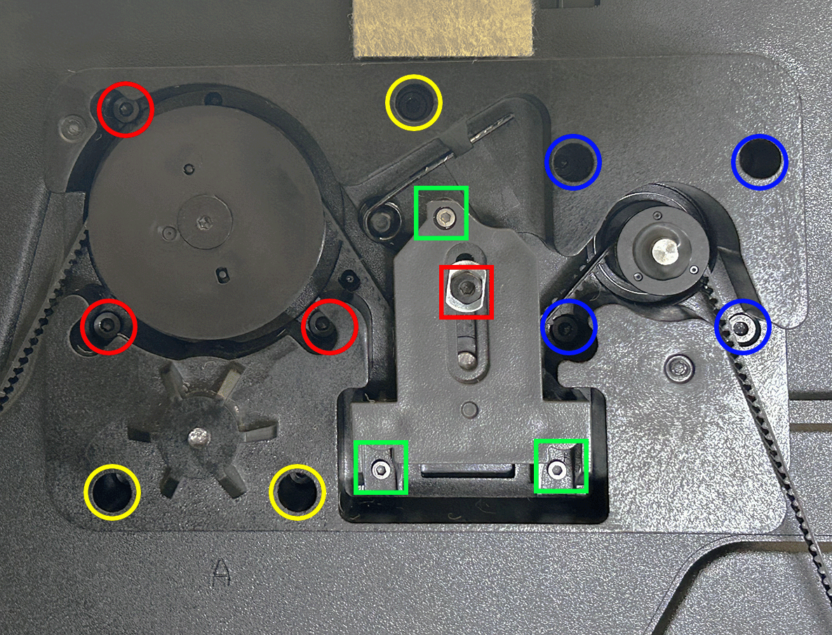
Using an H2.0 straight hex driver, remove the bottom mounting screws for the specific Z-axis lead screw you’re replacing (red circles).
-
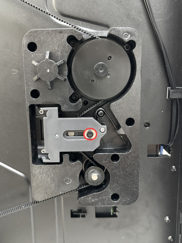
Refer to Replace H2D Z Belt/Z Belt Timing Pulley/Z-Axis Tensioner for steps to remove the Z-Axis Tensioner. Use an H1.5 straight hex driver to remove its three screws (green box) and one Z-axis tensioner slider mounting screw (red box).
-
Use an H2.0 straight hex driver to loosen the four Z-motor mounting screws (blue circles).
-
Use an H2.0 straight hex driver to loosen the relevant bottom-panel screws (yellow circles).
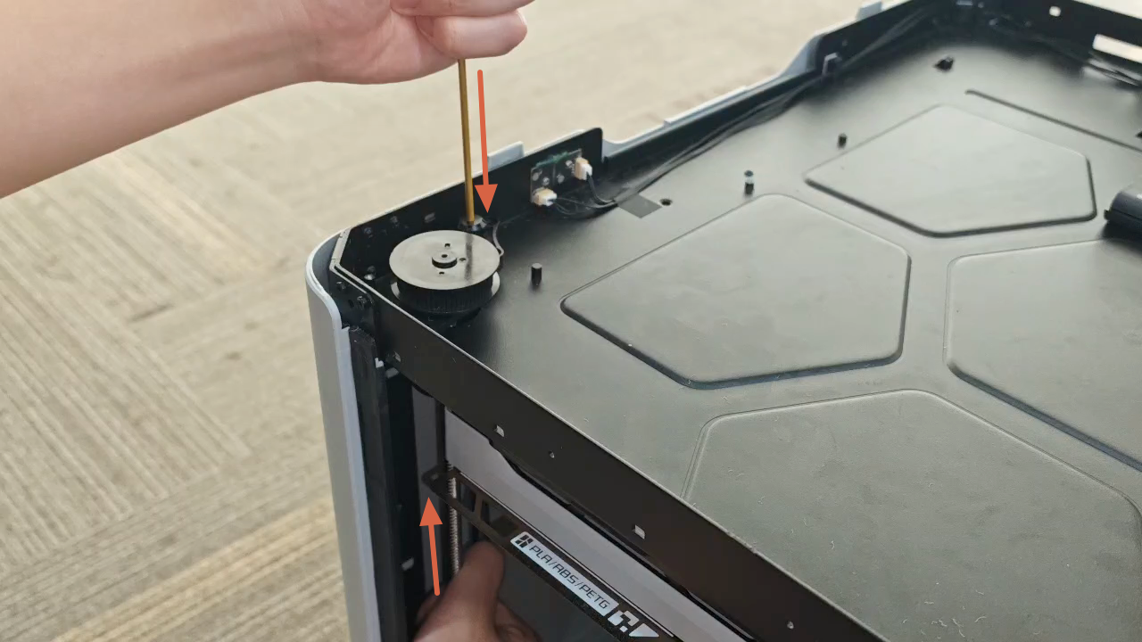
- Because the guide shaft is an interference fit, pulling the lead screw straight up can lift the guide shaft and its top adhesive dot out together. Two people are recommended for this step:
-
Person 1: From the bottom through-hole of the guide rod, lightly brace the end of the rod with a screwdriver to keep it from lifting.
-
Person 2: From inside the chamber, hold the lead screw firmly and push upward to gradually separate the lead-screw base from the guide rod.
Once the lead-screw base lifts slightly and you hear a faint “click” (the normal sound of the locating faces releasing), and you can feel a small gap open between the guide rod and its support, start withdrawing the lead screw so it gradually disengages from the lead-screw nut. Maintain a slow, steady rotation until the lead screw is fully removed.

¶ Optional: Removing the lead-screw nut (only if replacing or damaged)
If the lead-screw nut isn’t damaged, we don’t recommend removing or replacing it on its own. If you must, proceed:
- After removing the lead screw, please locate the lead screw nut (location shown below).
- Using an H2.0 L-shaped hex key to loosen the screws with small turns in the tight space. The top lead-screw nut has three fixing screws.
**Note: ** These top screws use the red-threadlocker screws. The first removal may require extra torque to break the threadlocker. Keep the driver seated to avoid cam-out or slipping that could scratch parts.
¶ Install the Rear Z-axis Lead Screw
¶ Optional: Pre-install the lead-screw nut to the heatbed locating hole (only if replacing or damaged)
To avoid fixing the nut to the lead screw first—making later alignment between the bed and lead screw difficult—we recommend pre-installing the nut into the heatbed locating hole. This step is for positioning only, not final tightening.
Note: If you fully tighten the lead-screw nut at this stage, any misalignment can load the lead screw unevenly during assembly and may bend it.
- Confirm the lead-screw nut orientation as shown below.
-
Place the lead-screw nut into the heatbed locating hole.
-
Use the red-threadlocker screws to tack it in place. Do not fully tighten yet, so you can fine-tune later.
-
Centering: ensure the lead-screw nut’s bore is concentric with the heatbed passthrough hole for the lead screw, so the screw will pass without rubbing.
¶ Step 1. Install the Lead Screw
From the bottom of the printer, feed the lead screw from top to bottom through the bottom opening. Gently adjust the lead-screw angle to line it up with the heatbed’s pre-installed nut. (There’s no self-locking—gravity will naturally draw the screw down.)

¶ Step 2. Fasten the Bottom Lead-screw Seat
-
Tighten the bottom fixing screws for the baseplate with H2.0 straight hex driver
-
Rrefer to H2D Z Belt/Z Belt Timing Pulley/Z-Axis Tensioner, and and install the three tensioners (green boxes) and the one Z-tensioner slider screw (red box).
-
Using an H2.0 straight hex driver, secure the four Z-axis motor fixing screws (blue circles).
-
If you replaced the lead-screw nut, again verify the lead-screw nut’s bore is perfectly concentric with the bed passthrough hole. Once aligned, tighten the three nut-fixing screws in sequence.(red circles)
¶ Step 3. Install the Rear Panel
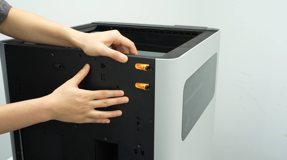
- Insert the rear panel at an angle into the bottom of the printer.
-
Use an H2.0 hex key to tighten 11 screws (marked with a red circle, ST3×6).
-
Use an H2.0 hex key to tighten 12 screws (marked with a green rectangle, BT3×8).

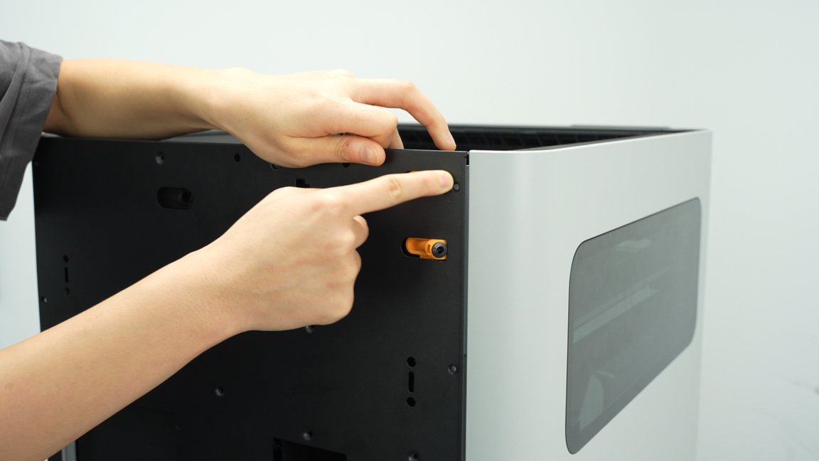
- Align the external spool bracket base with the holes on the back of the printer, then use an H2.0 hex key to tighten the two fixing screws;
¶ Tension the Z-axis Belt
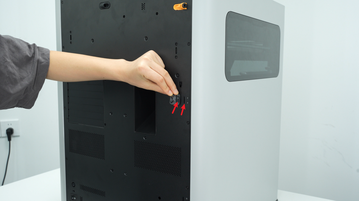
- Loosen the tensioner screw with an H2.0 straight hex driver (No need to remove it.)
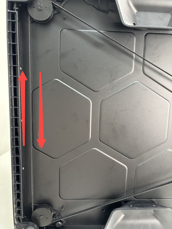
- Pull the Z belt back and forth a few times by hand to confirm smooth movement, then tighten the Z-axis tensioner slider fixing screw (M3×6) with an H2.0 straight hex driver.
 |
|
¶ How to Confirm It Worked
-
Plug the printer back in and power it on.
-
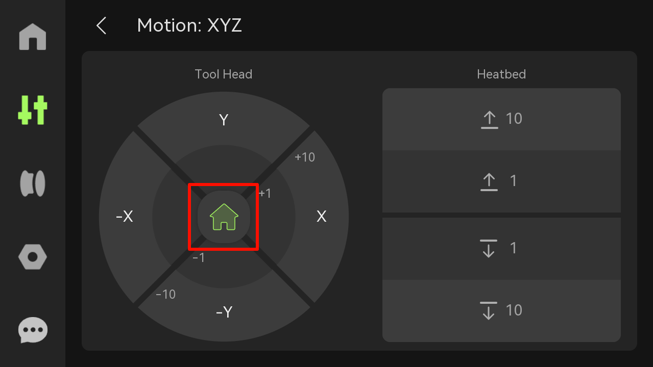
Click “Homing” to check if the printer can home correctly.
¶ End Notes
We hope the detailed guide provided has been helpful and informative.
If this guide does not solve your problem, please submit a technical ticket, we will answer your questions and provide assistance.
If you have any suggestions or feedback on this Wiki, please leave a message in the comment area. Thank you for your support and attention!