¶ AP board
The full name of AP board refers to the Application Processor Main Board, which is the power board that processes information interaction in the printer. It provides an independent operating environment for the printer and supports all system functions required by printer applications, including memory management, system firmware, graphics processing, and multimedia decoding.
The AP board spare parts include:
-
AP board * 1
-
BT3x5 screws - used to fix the AP board * 4
¶ When to use
It is necessary to contact Bambu Lab Technical Support to determine if the problem the printer has experienced is due to the AP board.
¶ Tools and materials needed
-
New AP board
-
H2.0 Allen key
Specifications and quantities of screws required to replace the H2D AP board (it is recommended to keep the removed screws properly to avoid loss):
| Specification | Image | Use | Position | Quantity | |
|---|---|---|---|---|---|
| BT2.6x8 | Fix the AP board cover |  |
1 | ||
| BT3x5 | Fix the AP board | 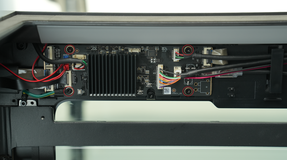 |
4 |
¶ Safety Warning
IMPORTANT!
It's crucial to power off the printer before conducting any maintenance work, including work on the printer's electronics and tool head wires. Performing tasks with the printer on can result in a short circuit, leading to electronic damage and safety hazards.
During maintenance or troubleshooting, you may need to disassemble parts, including the hotend. This exposes wires and electrical components that could short circuit if they contact each other, other metal, or electronic components while the printer is still on. This can result in damage to the printer's electronics and additional issues.
Therefore, it's crucial to turn off the printer and disconnect it from the power source before conducting any maintenance. This prevents short circuits or damage to the printer's electronics, ensuring safe and effective maintenance. For any concerns or questions about following this guide, we recommend submitting a technical ticket regarding your issue and we will do our best to respond promptly and provide the assistance you need.
Notes:
- For printers with replaced AP boards, skip the step of binding the printer when you start it for the first time.
Since the new SN is not activated, the binding operation cannot be performed. Binding can only be successful after the SN is activated.
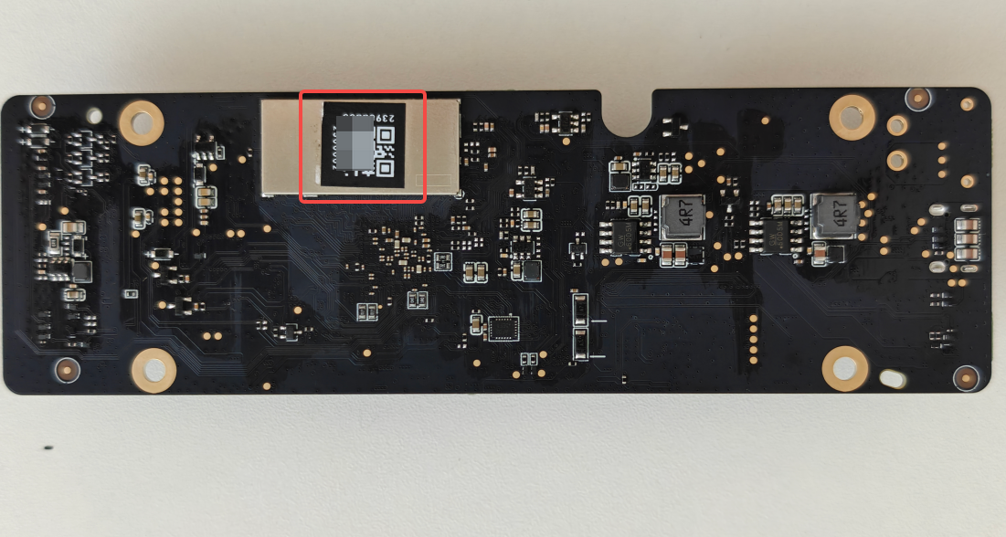
- After confirming that the replacement is complete, the SN needs to be replaced. Please contact Bambu Lab technical support and provide both the new and old SNs to complete the SN replacement. For how to obtain the SN of the new and old AP boards, please refer to this article: How to Find and Activate the Printer Serial Number. It is recommended to take a photo and save the SN of the AP board before replacing the AP board.
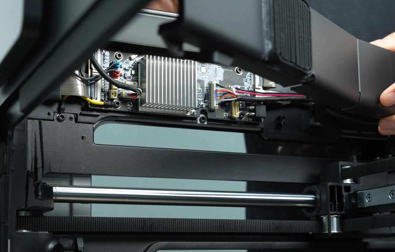
¶ Remove the AP board
¶ Step 1: Turn off the power
After turning off the printer, unplug the power cable and remove the glass cover plate.
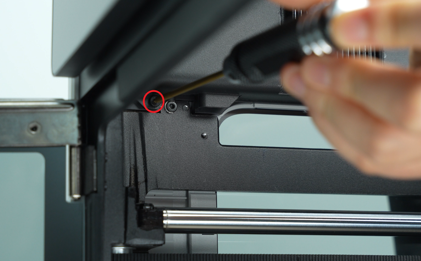
¶ Step 2: Remove the AP board cover
- Use an H2.0 Allen key to loosen 1 fixing screw (BT2.6x8) and open the AP board cover;
If you find it difficult to remove the AP board cover, you can refer to the relevant video steps in this wiki to perform the operation.
- Remove the AP board cover from the side near the front door.
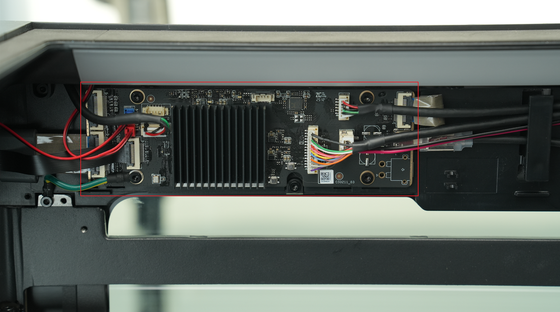
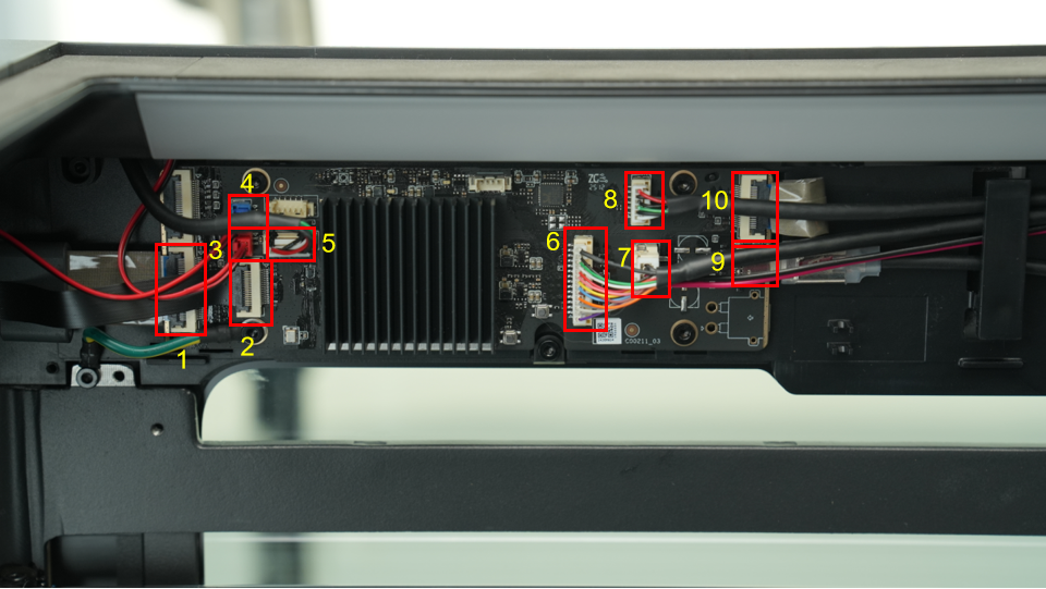
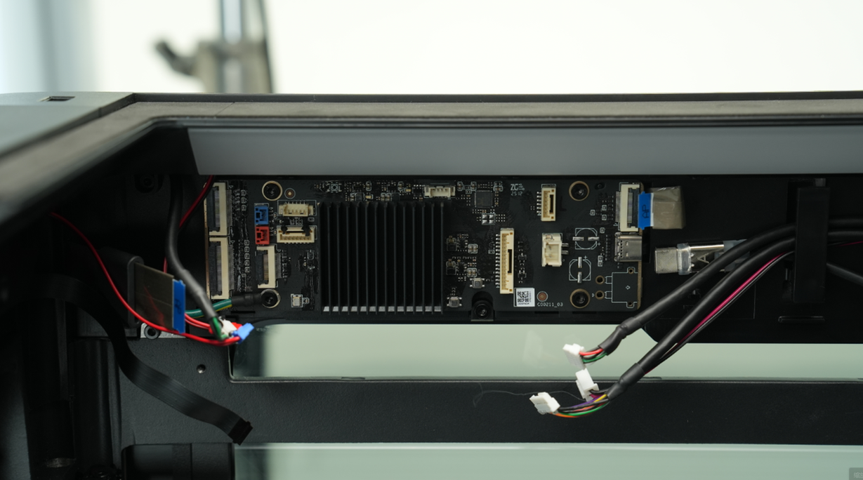
¶ Step 3: Disconnect the cables
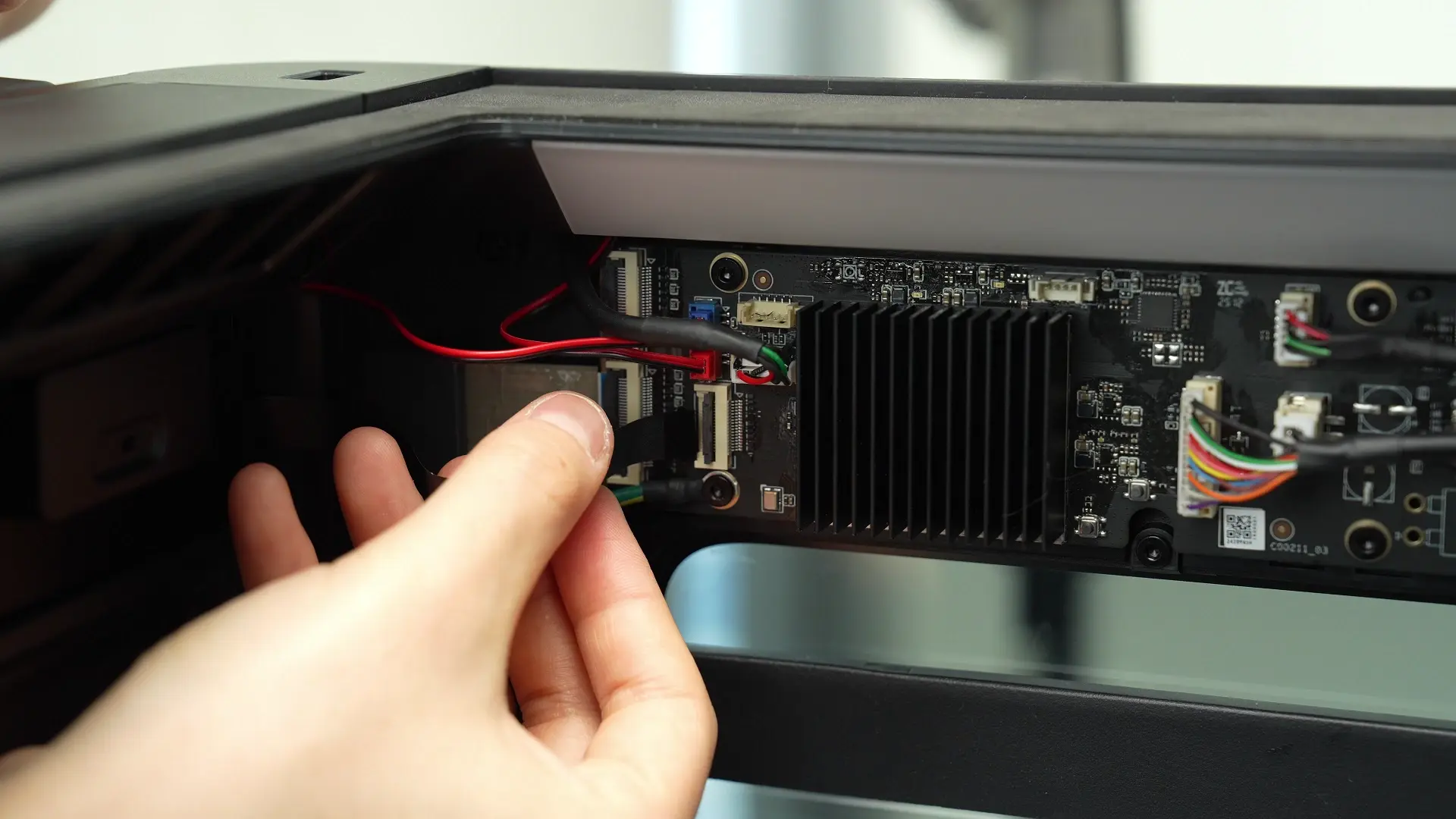
Unplug connectors 1 to 10 on the AP board in sequence.
-
Screen FPC
-
Wireless Network Board
-
Left LED light connector (red plug)
-
Right LED light connector (blue plug)
-
USB port board
-
MC-AP cable(communication)
-
MC-AP cable(power supply)
-
Ethernet Board
-
USB-C cable
-
Live view camera connector
Plug removal suggestions:
-
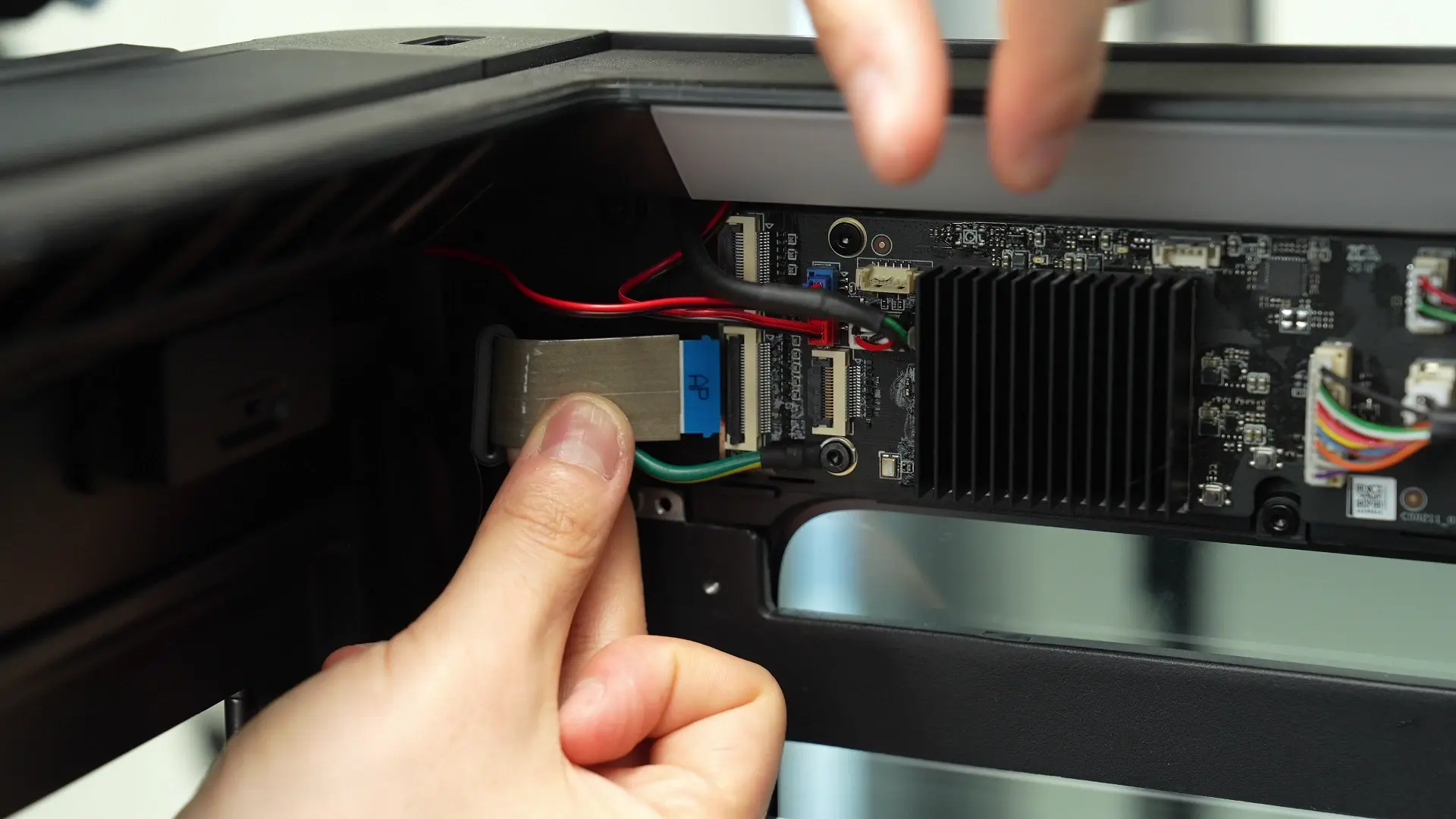
For FPC cable plugs such as #1, #2, and #10, you need to first open the buckle and then pull out the FPC cable.
-
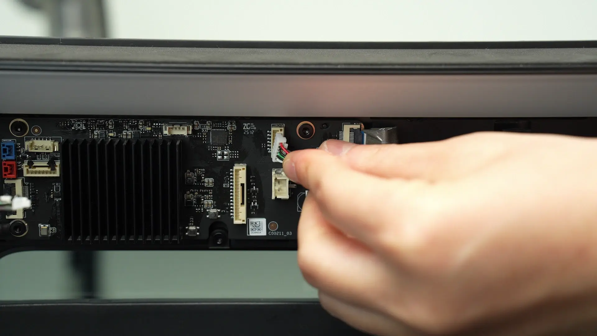
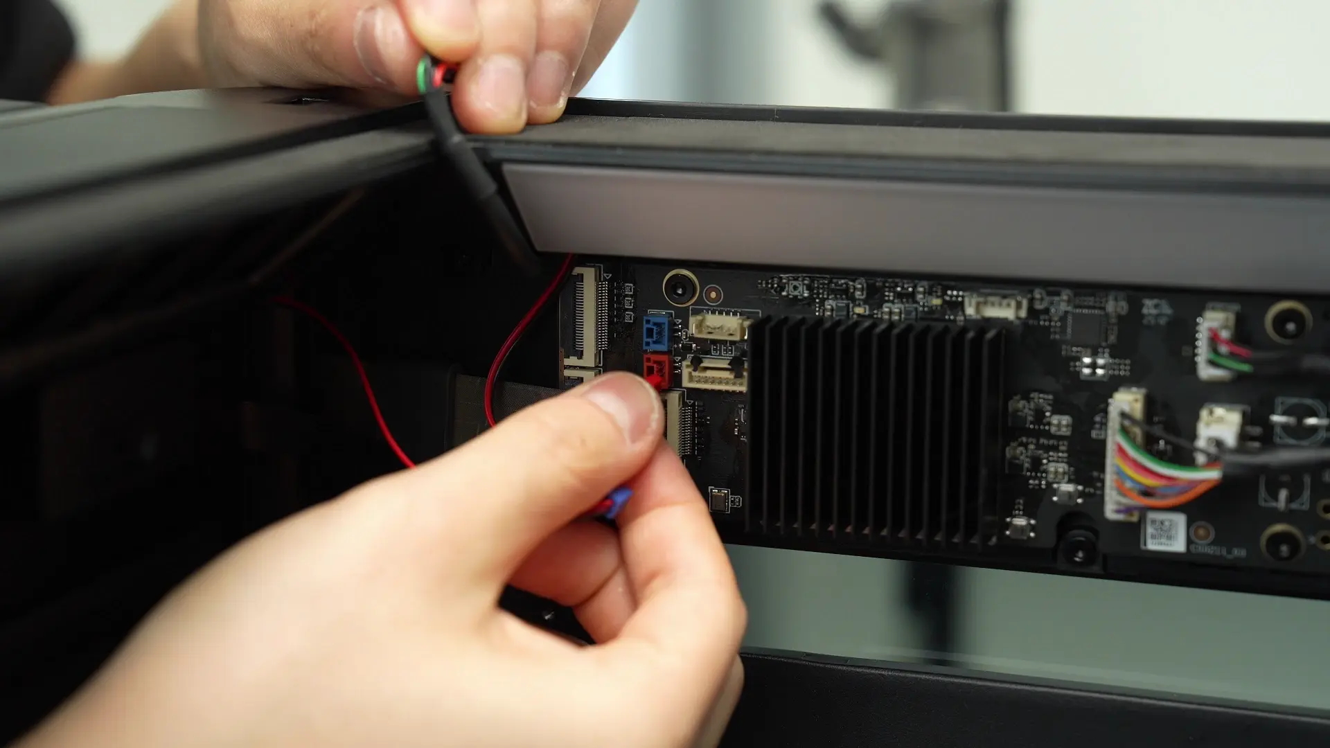
When unplugging #3, #4, #5, #6, and #8, you need to press the unlocking plug and then pull out the plug. Please refer to the following videos.
unplugging_suggestions_1_002.mp4
unplugging_suggestions_2_002.mp4
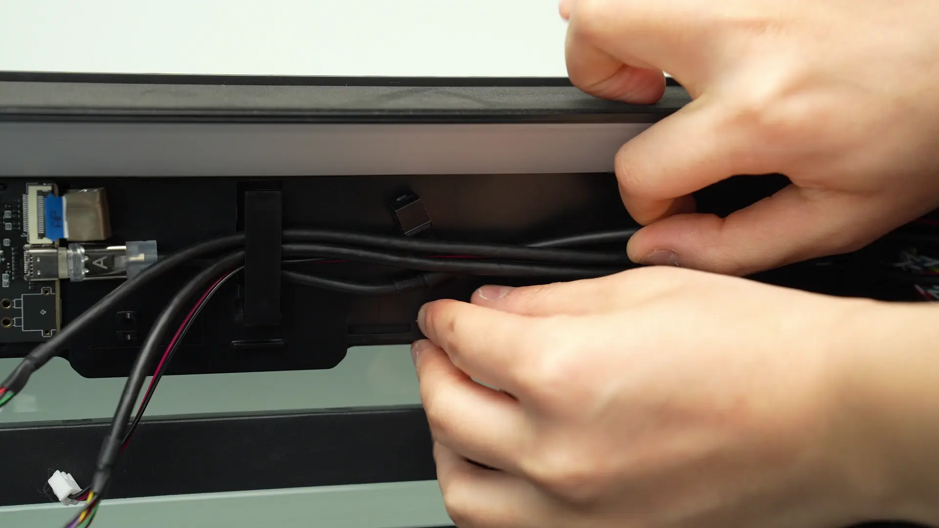
- If the #9 USB-C cable is difficult to unplug, you can push the cable toward the front of the printer with a little force to increase the length of the cable.
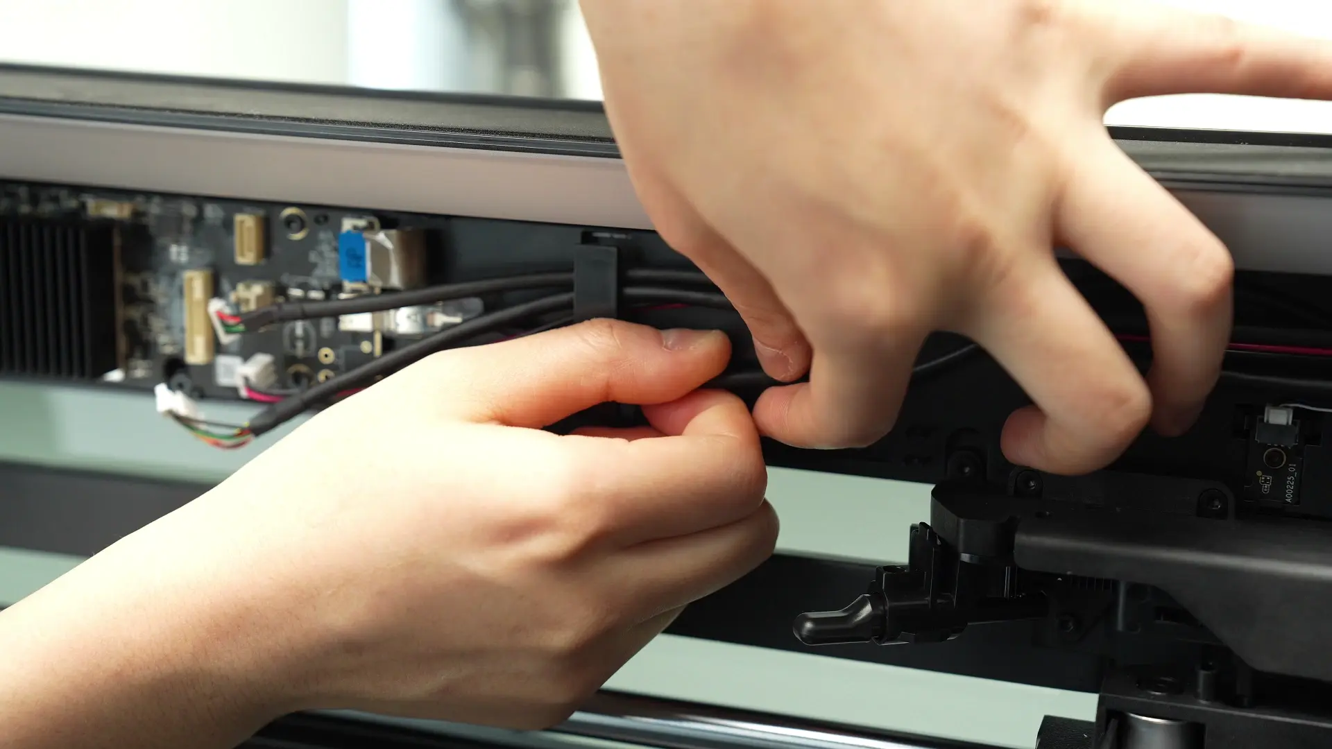
- Then, pull the cable toward the back of the printer with a little force and unplug the USB-C cable parallel to the AP board.
¶ Step 4: Remove the AP board
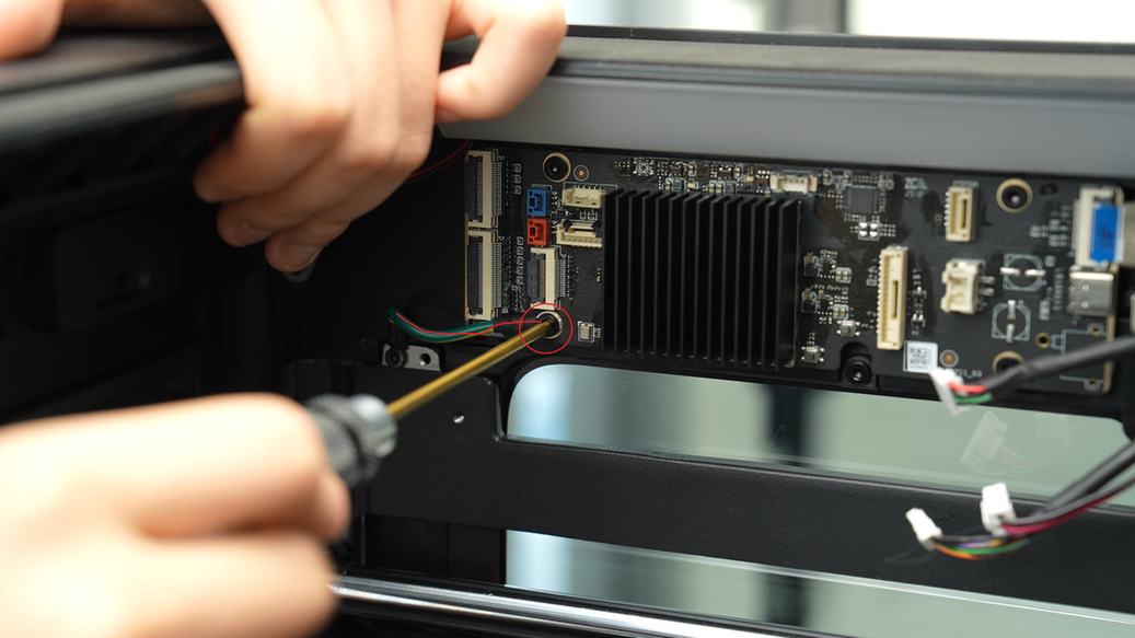
Use an H2.0 Allen key to loosen the 4 fixing screws (BT3×5), and then remove the AP board.
The fixing screw in the lower left corner of the AP board is connected to the ground wire. You can only unscrew the four screws on this end of the AP board (marked with red circles), and the screws connected to the chamber frame can remain intact.
¶ Install the AP board
¶ Step 1: Reinstall the AP board
Align the AP board with the screw holes on the upper frame and tighten the 4 fixing screws (BT3x5) using an H2.0 Allen key.
If your AP board has a ground wire at the fixing screw in the lower left corner, you can lock the ground wire and the AP board together when installing the fixing screw in the lower left corner of the AP board.
¶ Step 2: Connect the cables
Reinstall the connection cables on the AP board one by one.
-
Screen FPC
-
Wireless Network Board
-
Left LED light connector (red plug)
-
Right LED light connector (blue plug)
-
USB port board
-
MC-AP cable(communication)
-
MC-AP cable(power supply)
-
Ethernet Board
-
USB-C cable
-
Live view camera connector
Plug requirements:
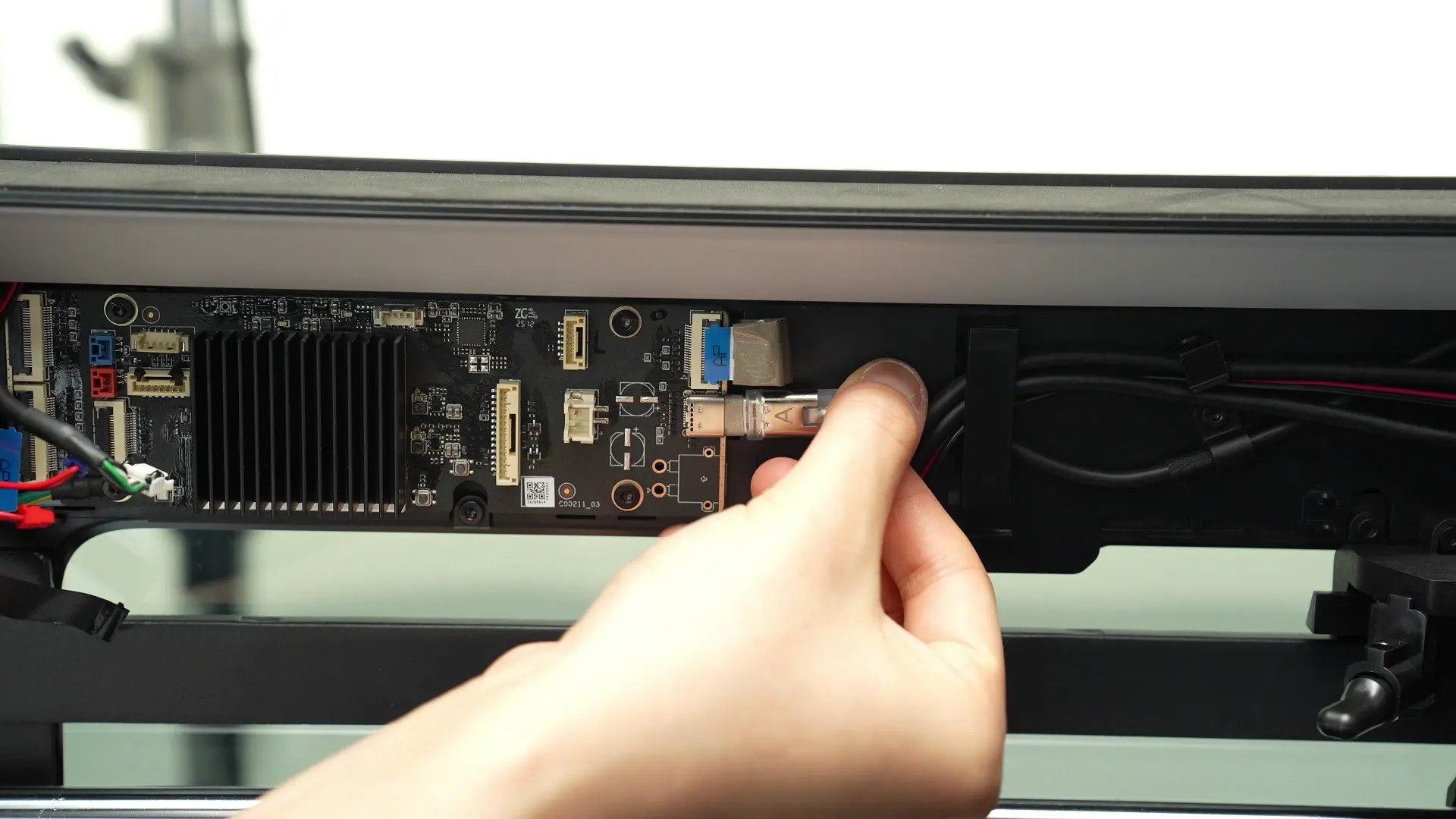
- Ensure the side of the USB-C cable (#9) labeled "A" faces the inside of the chamber when inserting. The connector is tight and may require some force to insert fully.
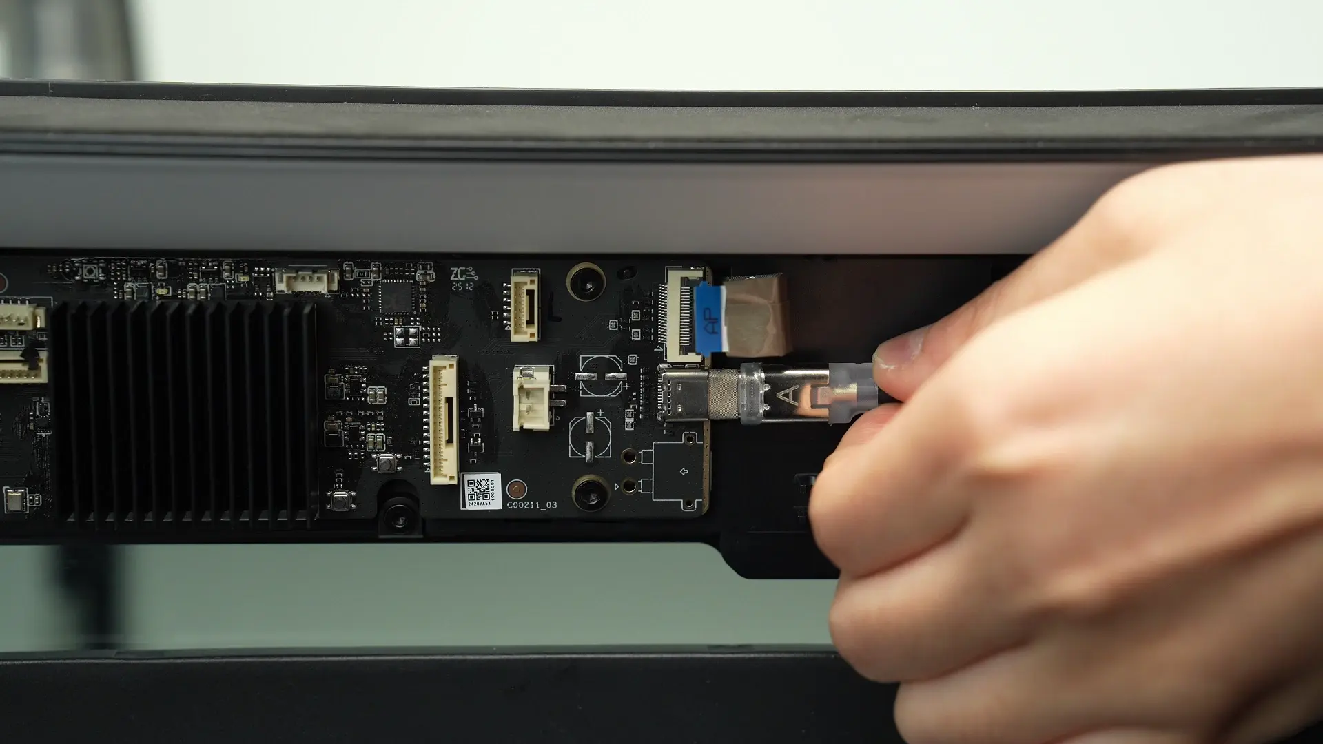
- After the connector is fully inserted, organize the cable. Be careful not to loosen the connector while arranging the cable.
- The small buckles on the left and right sides of the screen cable (#1), wireless network board (#2) and live view camera connector (#10) need to be embedded in the socket.
#1 and #10 need to have the side with the word "AP" facing the inside of the chamber, and ensure that the buckle is flat and not raised on one side after buckling.
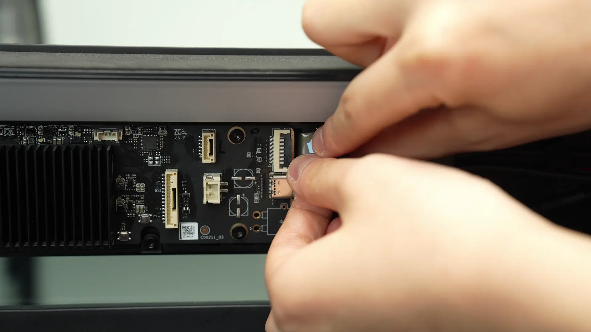
- When connecting cables #3, #4, #5, #6, and #8, make sure to align them properly with the latch direction before insertion.
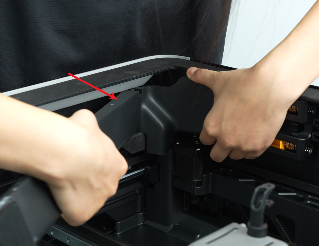
¶ Step 3: Reinstall the AP board cover
Note: Before installing the AP board cover, check that the cables do not obstruct the PTFE tube path to avoid issues with later PTFE installation.
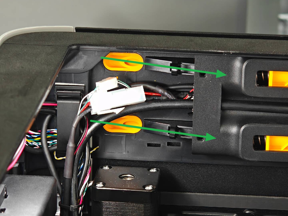
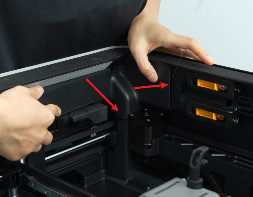
- Snap the AP board cover back from the side close to the back of the printer, press the two places indicated by the arrows into place, flush with the buffer on the right side and flush with the cable cover on the bottom;
- Tighten a fixing screw (BT2.6x8) using an H2.0 Allen key.

¶ Verify the Functionality
Connect the power cable and turn on the power. Initiate a print and check if there is an error.
Otherwise, check if all cables on the AP board are properly connected and try again. If the problem persists, contact Bambu Lab technical support for further assistance.
¶ End Notes
We hope the detailed guide provided has been helpful and informative.
If this guide does not solve your problem, please submit a technical ticket, we will answer your questions and provide assistance.
If you have any suggestions or feedback on this Wiki, please leave a message in the comment area. Thank you for your support and attention!