¶ Ethernet Board
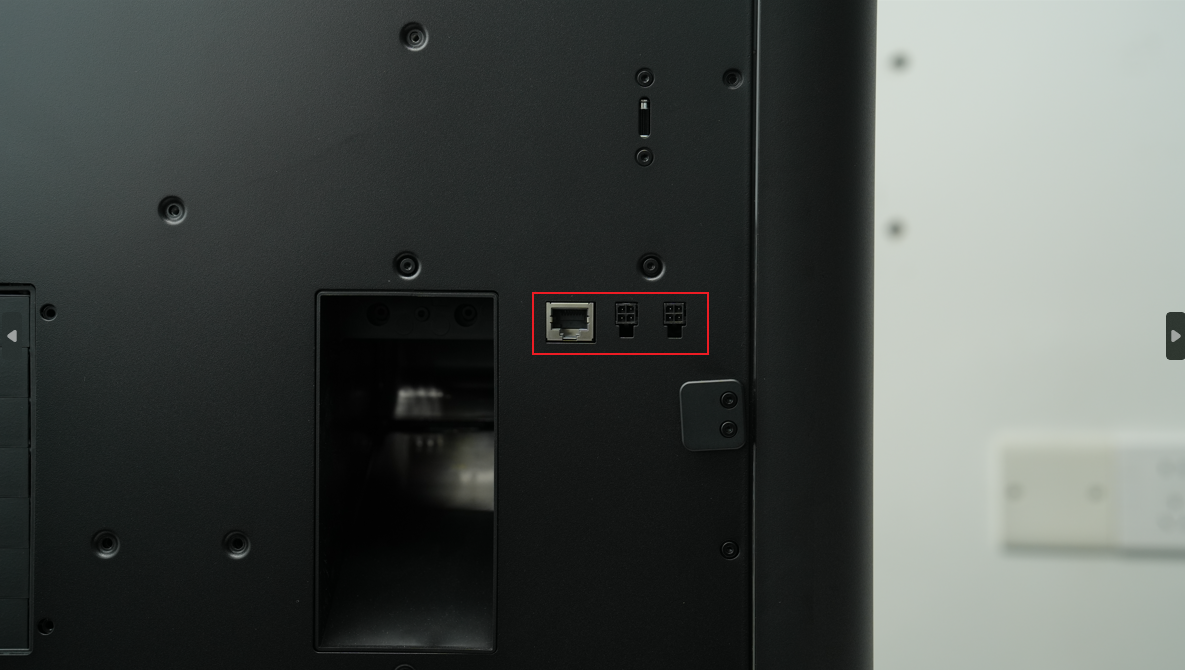
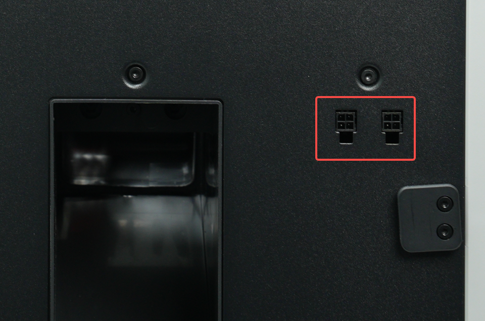
The Ethernet board is installed on the back of the printer, providing a wired network interface and two 4-pin interfaces. The 4-pin interface can be used to connect an external air pump and expansion boards that may be supported in the future.
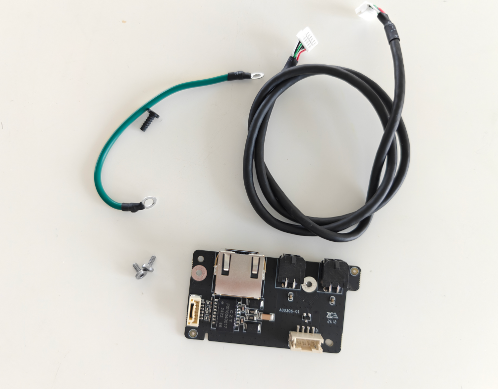
The spare parts of the Ethernet Board include the following:
-
Ethernet Board
-
BT2x5 screws - used to fix the 4pin interface board * 2
-
Ground wire screw
-
Ground wire
-
Ethernet Board - AP board cable
In most cases, the cable is not easily damaged, so you do not need to replace the cable. You only need to replace the Ethernet board in the accessory box. If the cable is found to be obviously damaged, you can refer to the steps in the appendix to replace the cable.
¶ When to use
- When the Ethernet board or 4-pin interface fails, it needs to be replaced.
¶ Tools and Materials Needed
-
New Ethernet board
-
H2.0 Allen key
| Specification | Image | Use | Position | Quantity | |
|---|---|---|---|---|---|
| BT3x8 | Fix the rear panel |  |
12 | ||
| ST3x8 | Fix the rear panel |  |
11 | ||
| ST3x12 | Fix the spool holder bracket | 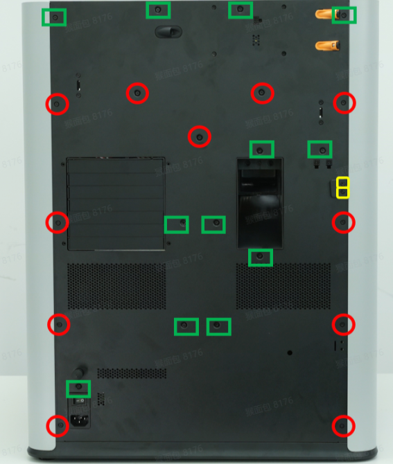 |
2 | ||
| BT2x5 | Fix the 4pin interface board | 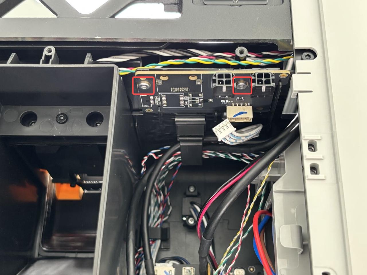 |
2 |
¶ Safety Warning
IMPORTANT!
It's crucial to power off the printer before conducting any maintenance work, including work on the printer's electronics and tool head wires. Performing tasks with the printer on can result in a short circuit, leading to electronic damage and safety hazards.
During maintenance or troubleshooting, you may need to disassemble parts, including the hotend. This exposes wires and electrical components that could short circuit if they contact each other, other metal, or electronic components while the printer is still on. This can result in damage to the printer's electronics and additional issues.
Therefore, it's crucial to turn off the printer and disconnect it from the power source before conducting any maintenance. This prevents short circuits or damage to the printer's electronics, ensuring safe and effective maintenance. For any concerns or questions about following this guide, we recommend submitting a technical ticket regarding your issue and we will do our best to respond promptly and provide the assistance you need.
¶ Remove the Ethernet board
¶ Step 1: Remove the rear panel
Refer to Replace H2D Rear Panel for instructions on removing the H2D Pro rear panel.
Note: The disassembly and assembly method of the rear panel of H2D Pro is exactly the same as that of H2D. The difference is that the rear panel of H2D Pro has an additional Ethernet port.
 H2D Pro rear panel |
 H2D rear panel |
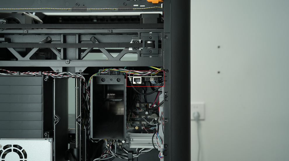
¶ Step 2: Remove the Ethernet board
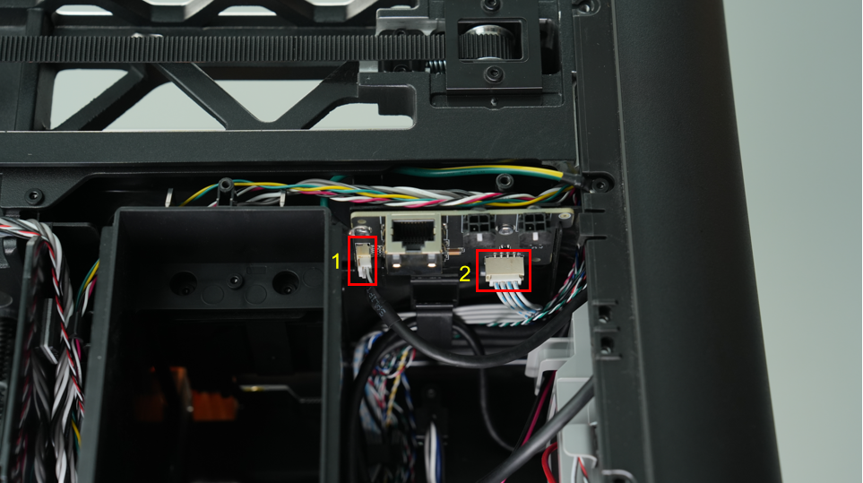
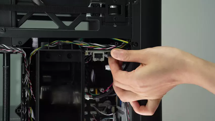
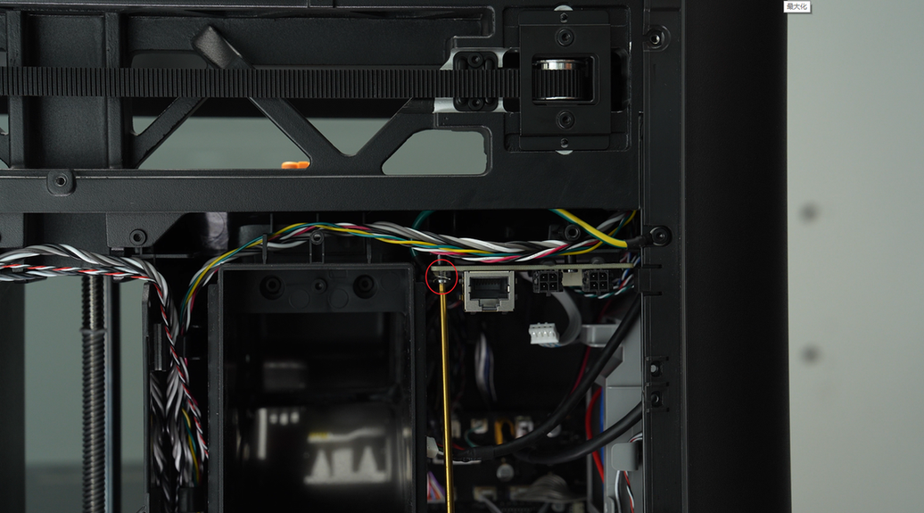
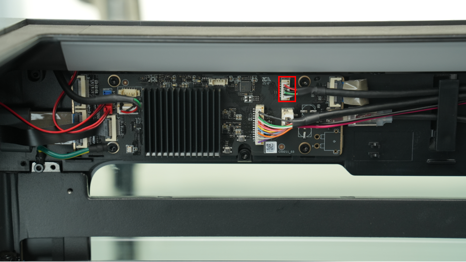
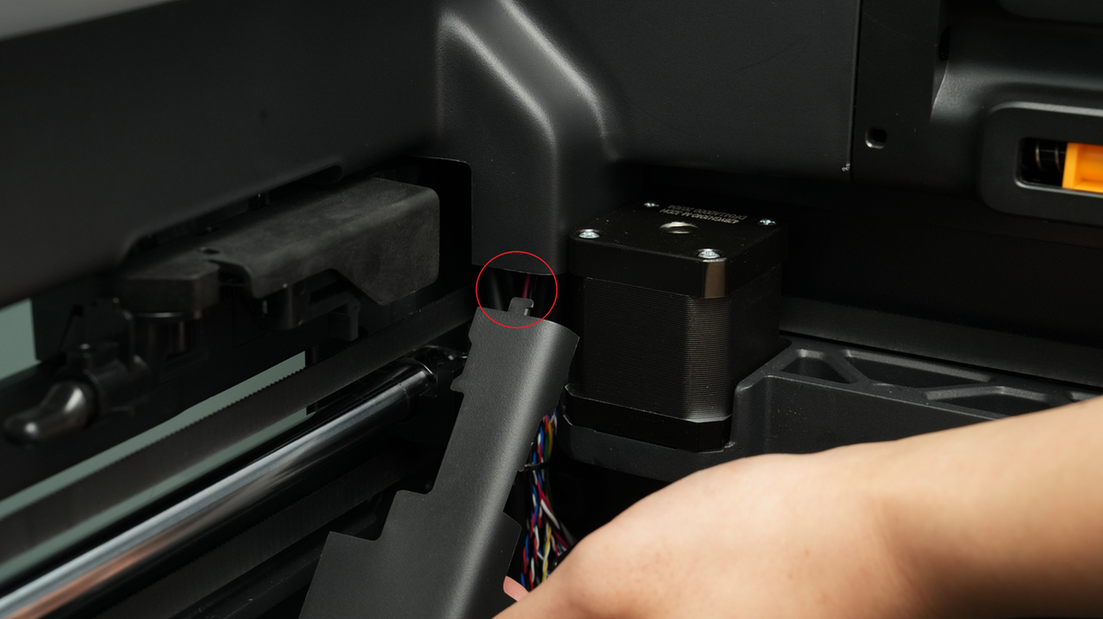
- Disconnect the cable from the Ethernet board;
-
#1: Ethernet port on the AP board; to disconnect, press the left side to release the plug buckle
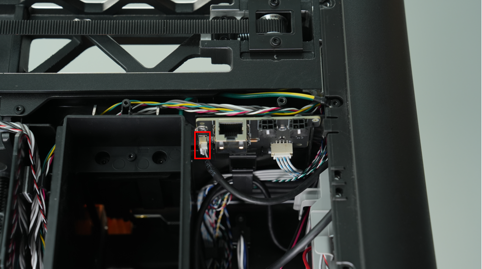
-
#2: 4-pin expansion port on the MC board
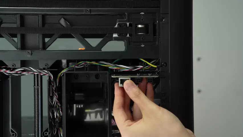
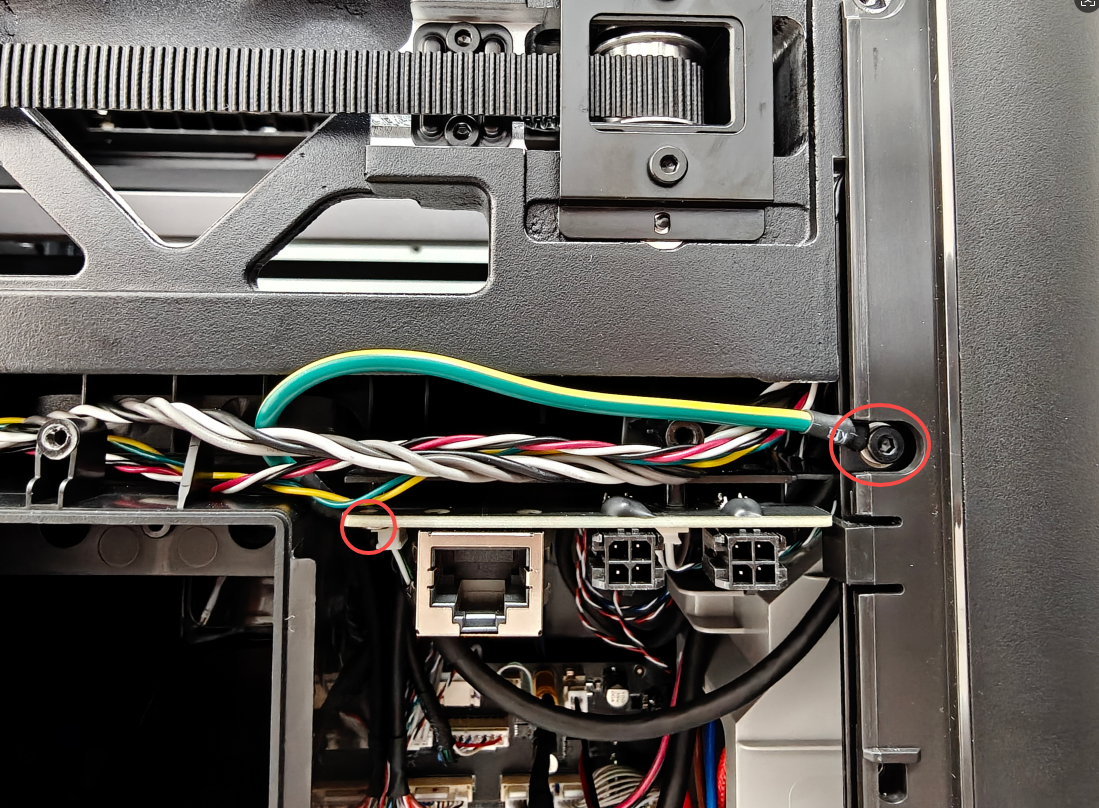
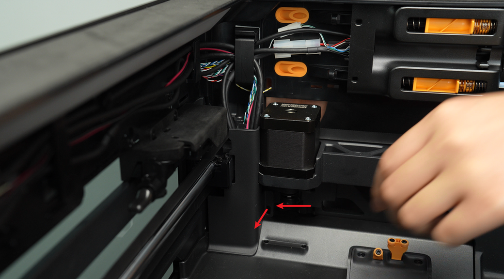
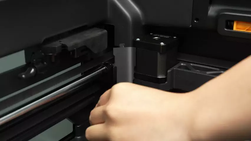
- Use an H2.0 Allen key to remove the 2 fixing screws (BT2x5);
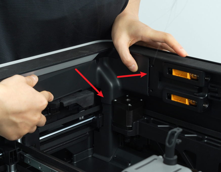
- Push back and remove the 4-pin interface board.
¶ Install the Ethernet Board
¶ Step 1: Install the new Ethernet Board
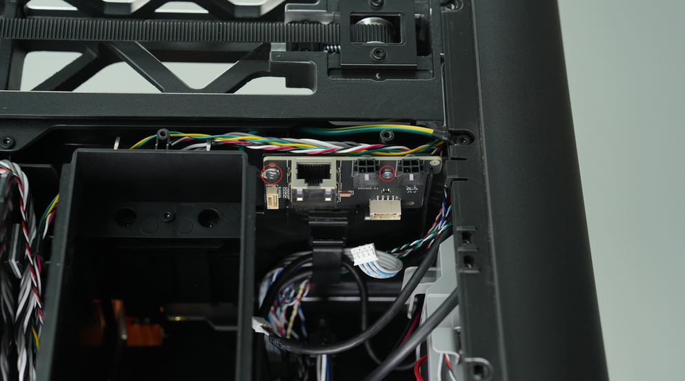
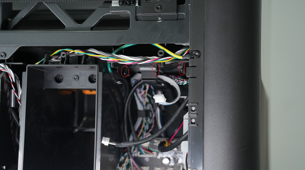
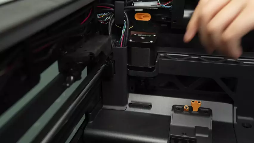
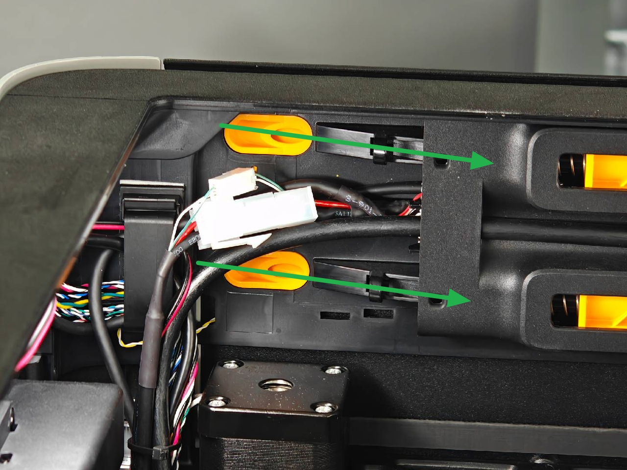
- Push the Ethernet board in along the direction of the three slots.
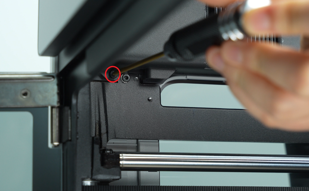
- Align the Ethernet board with the two screw holes, and tighten the two fixing screws (BT2x5) with an H2.0 Allen key;
Note: When locking the left screw, you need to lock the ground wire at the same time.
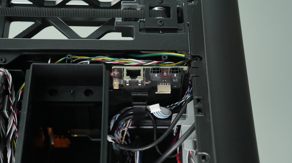
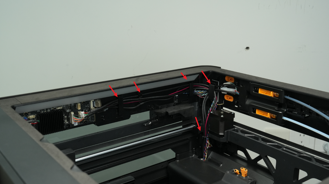
- Reconnect the 2 plugs on the Ethernet board. After connecting, route the cables as shown. Ensure that the ground wire is not pressed against the screw post.
¶ Step 2: Reinstall the rear panel
Refer to Replace H2D Rear Panel for instructions on installing the H2D Pro rear panel.
¶ Appendix: Replace the signal cable and ground wire between the Ethernet board and the AP board
¶ Replace the ground wire
If you need to replace the ground wire, just remove the two screws and replace the new ground wire.
¶ Replace the signal cable
If you need to replace the signal cable between the Ethernet board and the AP board, please refer to the following steps:
¶ Remove the AP board cover and cable cover
- Use an H2.0 Allen key to remove one mounting screw (BT2.6x8) and open the AP board cover.
If you find it difficult to remove the AP board cover, you can refer to the relevant video steps in this wiki to perform the operation.

- Remove the AP board cover from the side near the front door.
- Apply forward force to carefully pry out the cable cover.
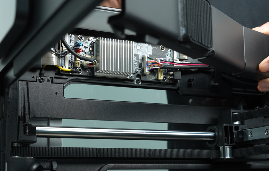
- Press the clips on the AP board and the wired Ethernet board to release the connectors. Disconnect the interfaces and pull the cables out through the cable routing opening.
¶ Replace the cables
As shown above, snap the cable into the slot and connect the plug.
¶ Install the AP board cover and cable cover
Note: Before installing the AP board cover, check whether the cables are blocking the PTFE tube to avoid affecting the subsequent installation of the PTFE tube.
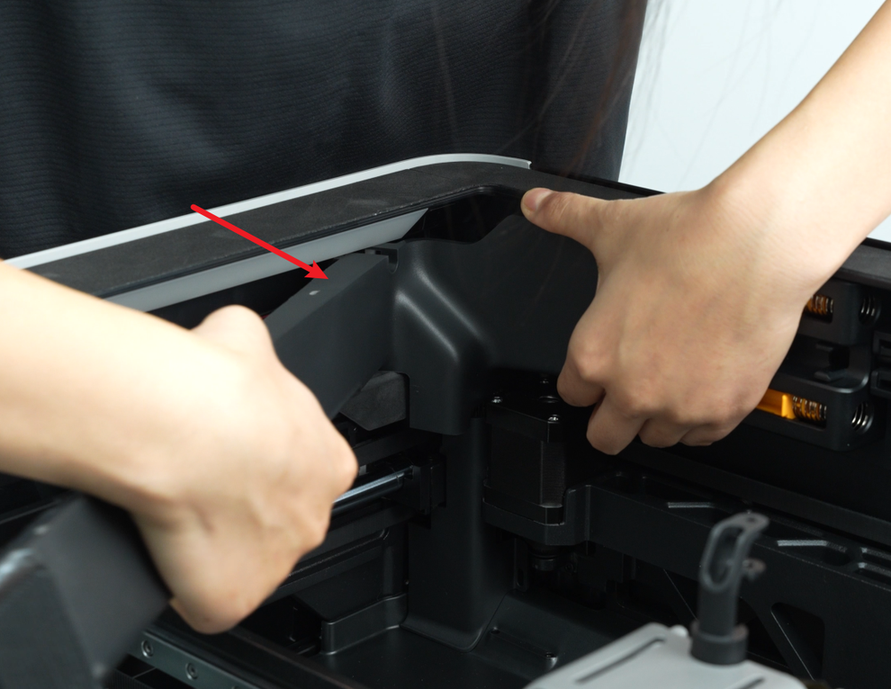
- First, snap the AP board cover back from the side close to the back of the printer, press the two places indicated by the arrows into place, flush with the buffer on the right side and flush with the cable cover on the bottom, and then tighten a fixing screw (BT2.6x8) with an H2.0 Allen key.
- Align the cable cover with the buckles on the AP board and push it backwards.
¶ Verify the Functionality
Connect the power supply and turn on the printer to check whether the external air pump or extension board can be used normally.
¶ End Notes
We hope the detailed guide provided has been helpful and informative.
If this guide does not solve your problem, please submit a technical ticket, we will answer your questions and provide assistance.