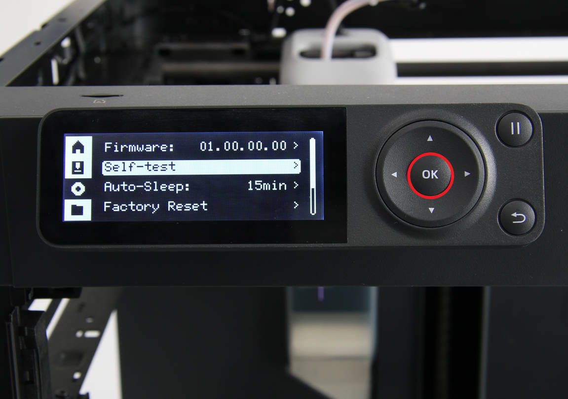
¶ Heat bed signal cable
Click here to see replacement guide for X1 series.
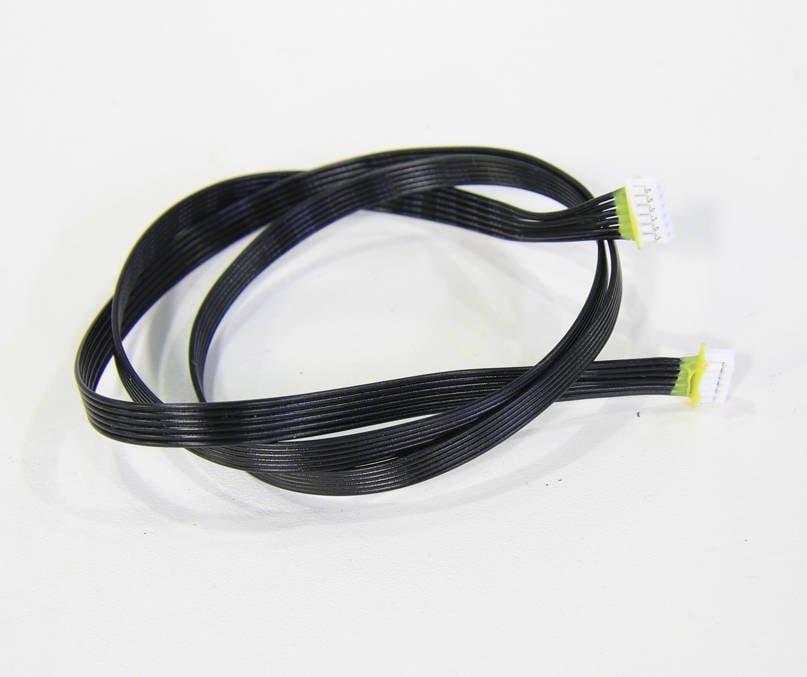
¶ Tools
H2.0/1.5 hex key
Tweezers
¶ Preparation
Disconnect the power cord cable
¶ Disassembly
¶ Step 1 - Remove the rear panel and excess chute
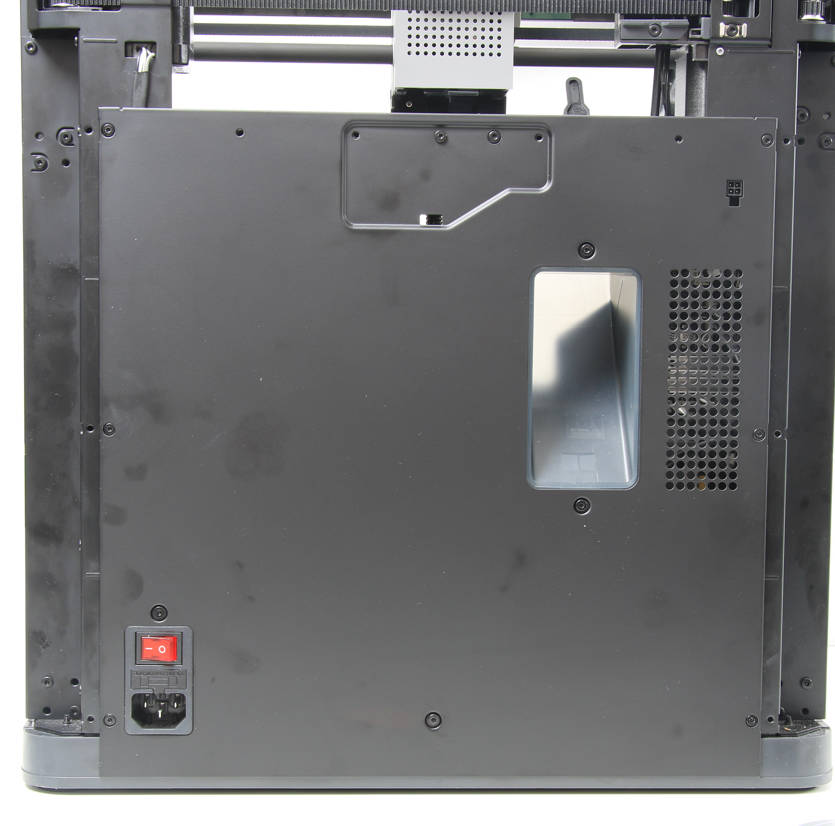
Refer to the related contents of the Rear panel and Excess chute to remove the rear panel and the excess chute.
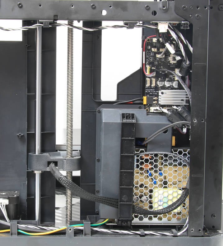
¶ Step 2 - Remove the cable railing
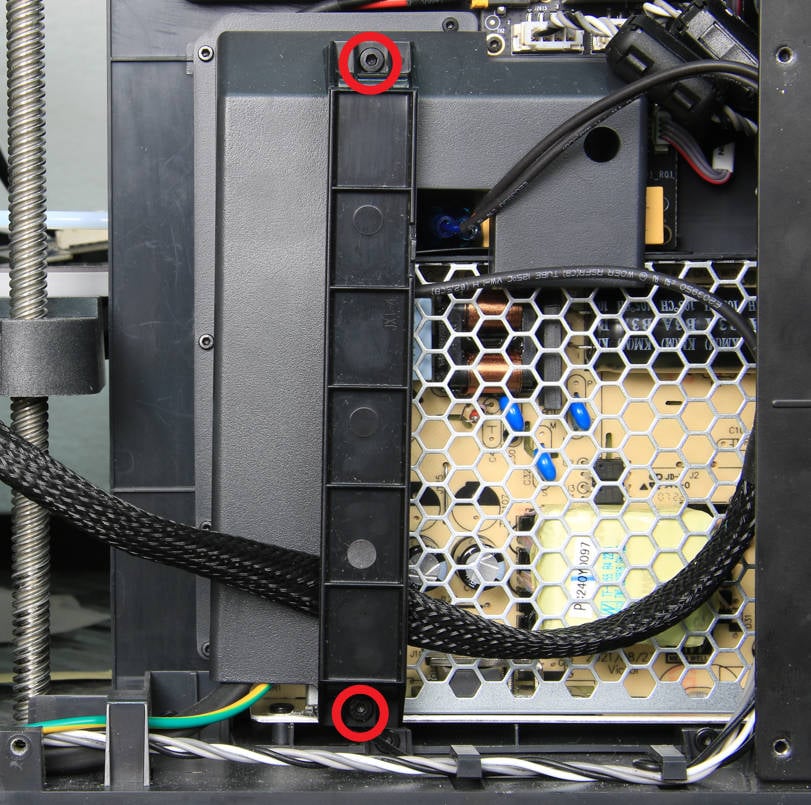
Remove 2 screws with an H2.0 hex key and remove the cable railing.
¶ Step 3 - Disconnect the heat bed signal cable
Disconnect the MC-AC connection cable first, then remove the silicone on the heat bed signal cable, and then disconnect the signal cable.
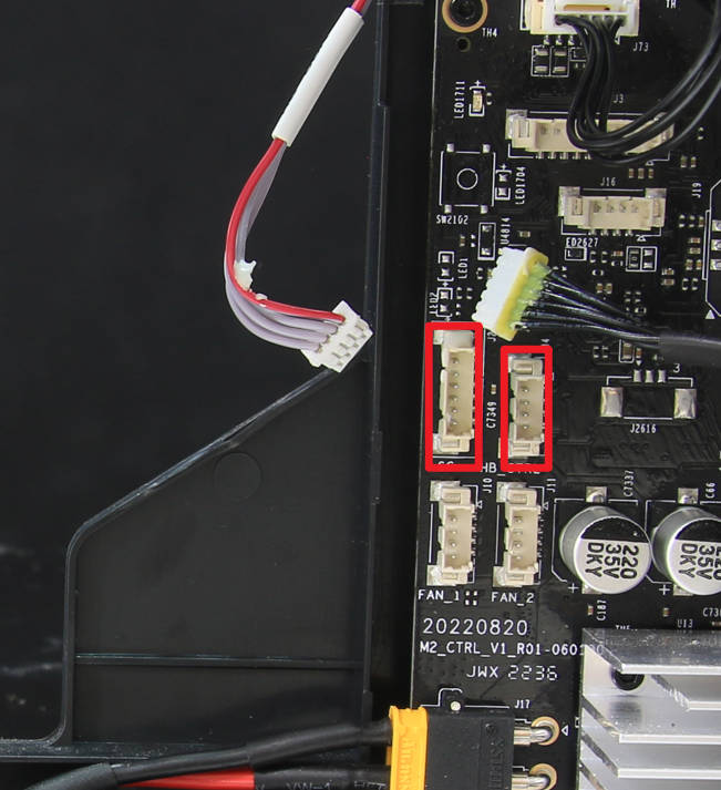
¶ Step 4 - Loosen the heat bed signal cable from the cable mesh
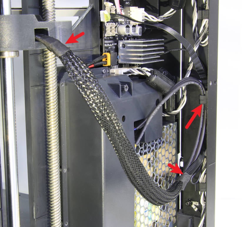
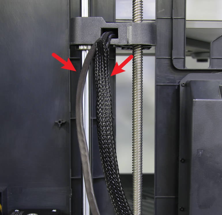
Loosen the heat bed cables from the cable buckles, tear off the tape at both ends of the cable mesh and pull out the signal cable.
 |
 |
¶ Step 5 - Raise the heat bed
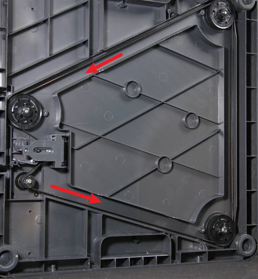
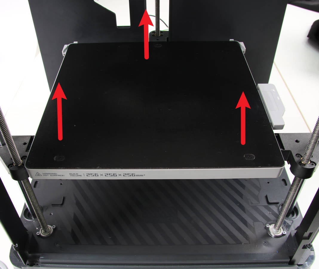
Put the printer on its right side, and raise the heat bed to about 2/3 of the full distance by pulling the Z-axis belt.
 |
 |
¶ Step 6 - Remove the holding plate
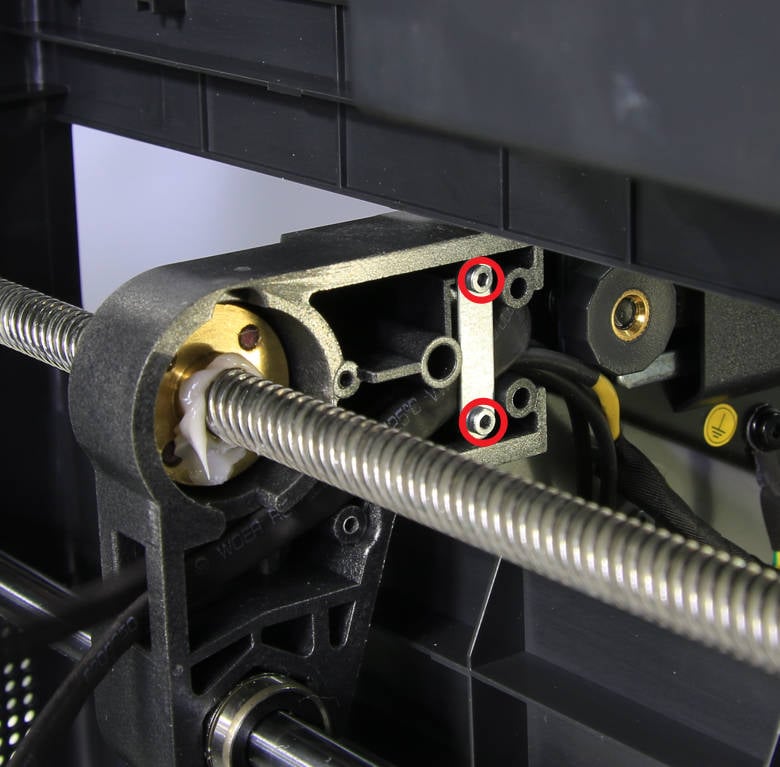
Unscrew 2 screws and remove the holding plate.
¶ Step 7 - Unlock the heat bed
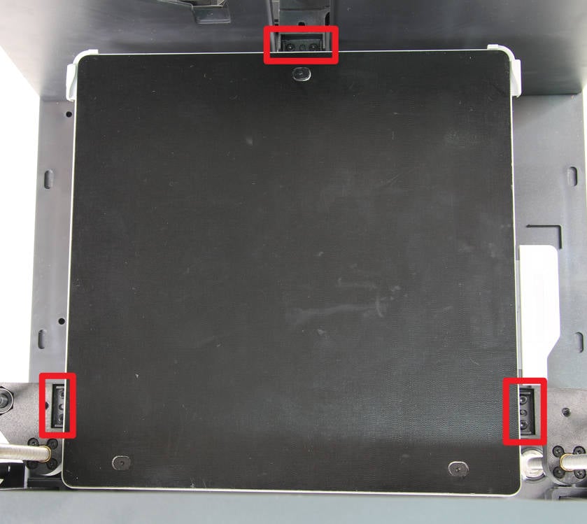
Put the printer upright again, and remove the 6 screws that fix the heat bed.
¶ Step 8 - Take off the heat bed
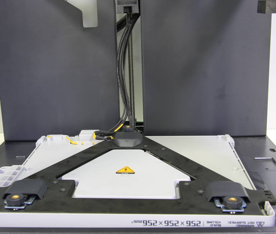
Turn the heat bed over, pull the cables towards the heat bed a little bit, and then place the heat bed face down on the bottom surface of the printer.
¶ Step 9 - Remove the leveling nuts
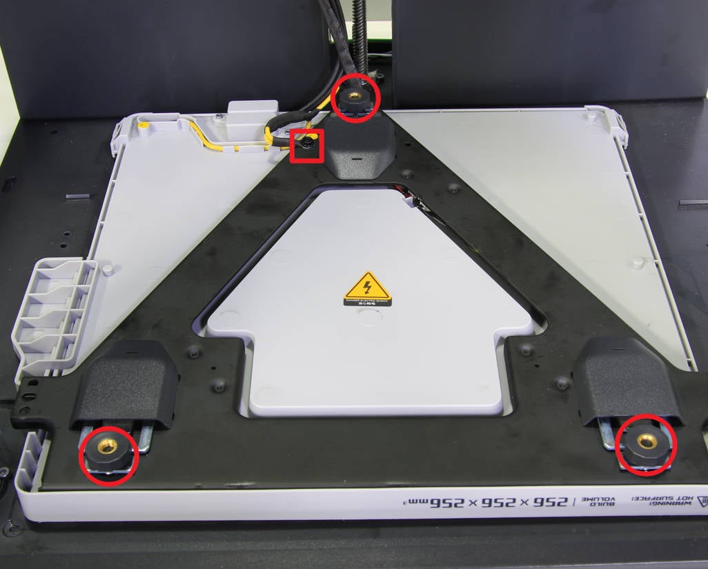
Remove the 3 leveling nuts and rubbers, and remove the ground cable fixing screw.
¶ Step 10 - Open the heat bed bracket
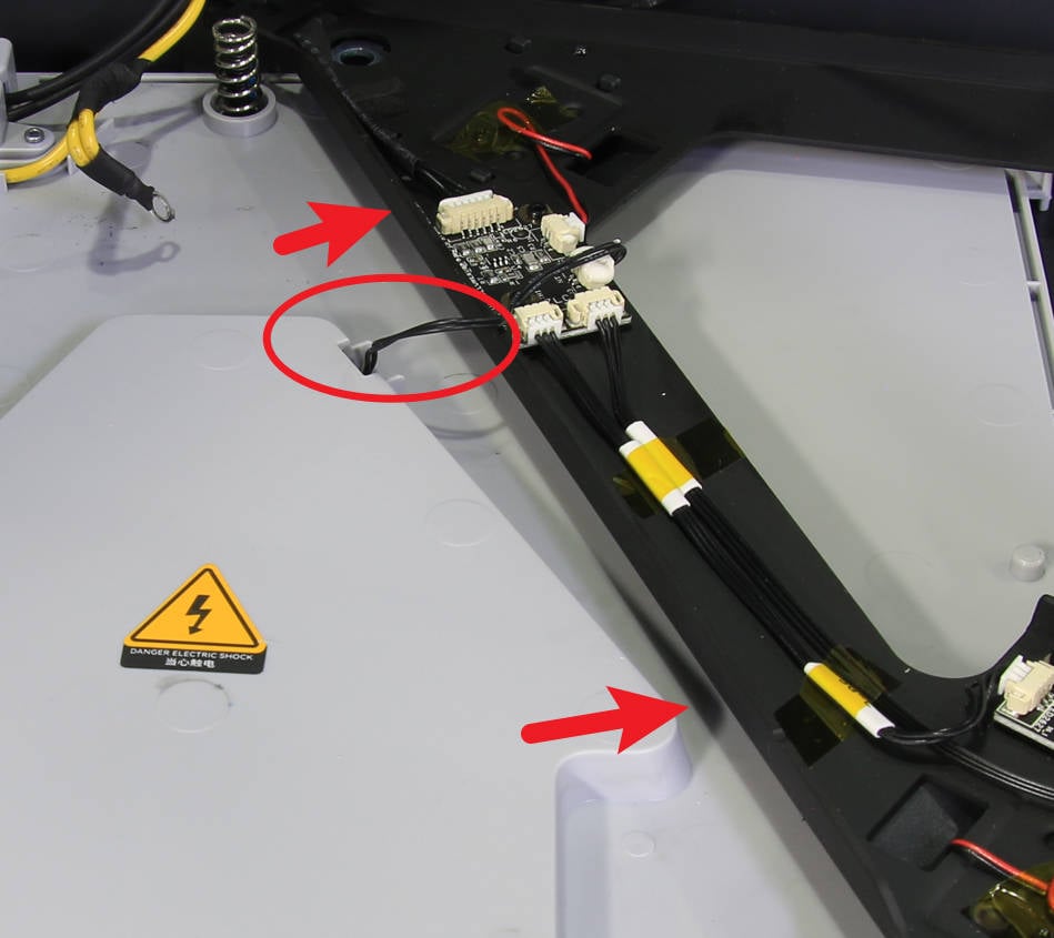
Flip from left to right to open the heat bed bracket, note that there is a 2PIN cable connecting on the board, do not damage it.
¶ Step 11 - Remove the heat bed signal cable
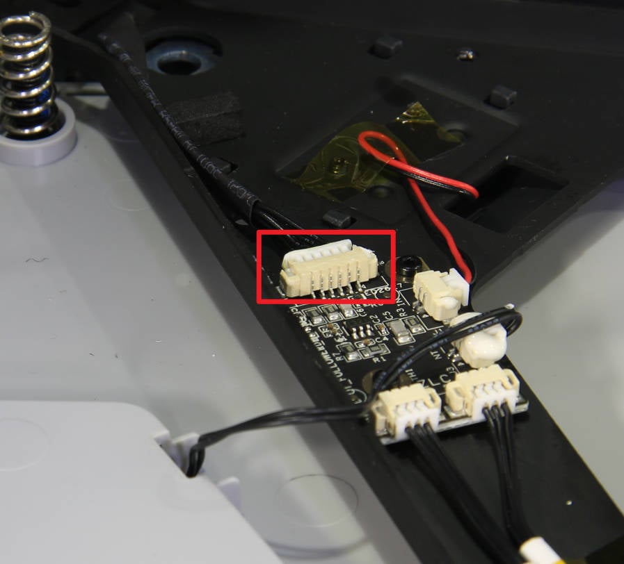
Clean the silicone glue on the heat bed signal cable connector, disconnect it, and then remove the heat bed signal cable.
¶ Assembly
¶ Step 1 - Connect the heat bed signal cable
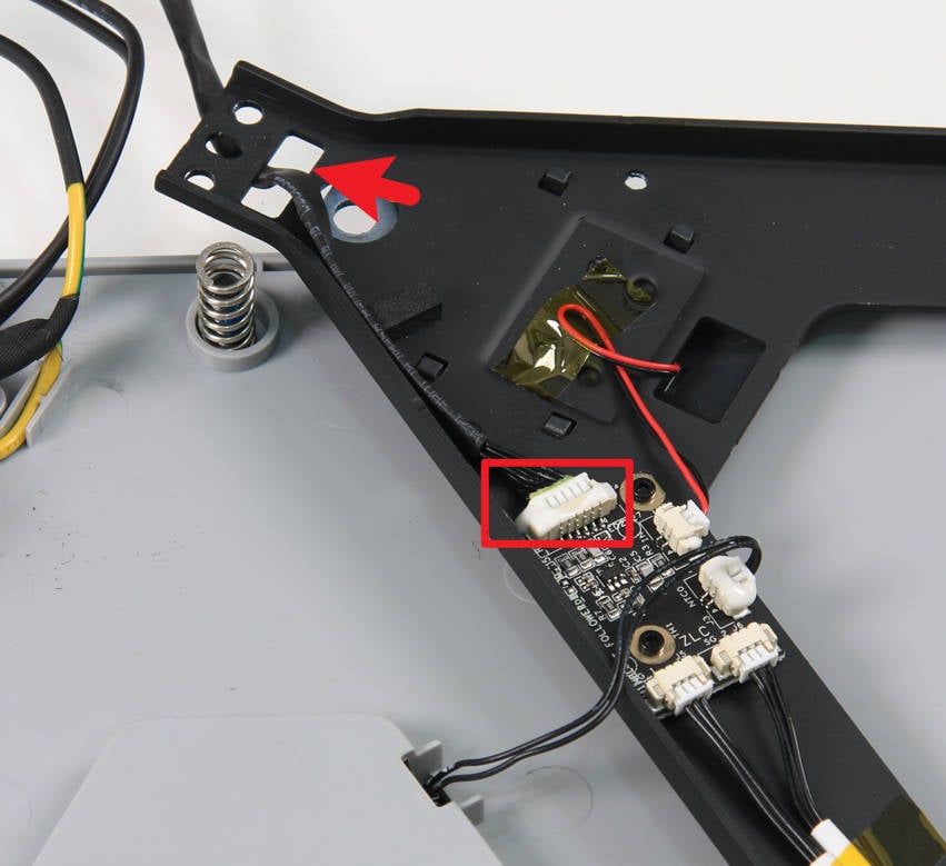
Pass the heat bed signal cable through the cable hole on the heat bed bracket, connect to the connector on the board, and reinforce it with silicone glue.
¶ Step 2 - Set the heat bed bracket
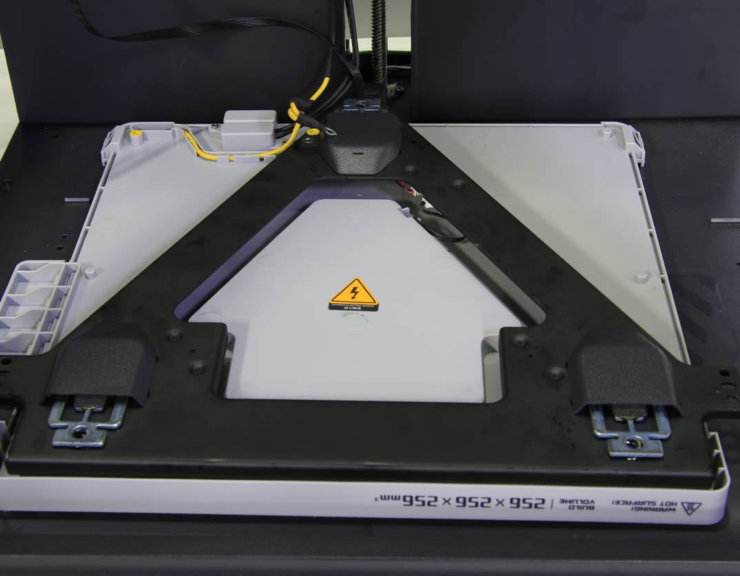
Set the heat bed bracket and adjust the position.
¶ Step 3 - Install leveling nuts
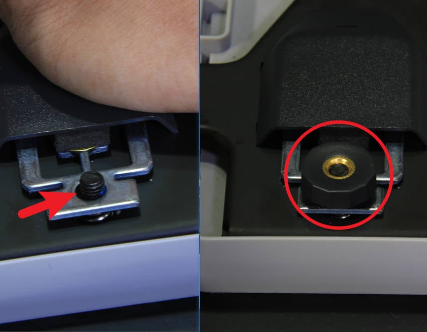
Press the heat bed bracket to to expose the studs, screw in the 3 leveling nuts one by one, try to screw them in the same height, and then lock the ground cable.
 |
 |
¶ Step 4 - Installing the heat bed
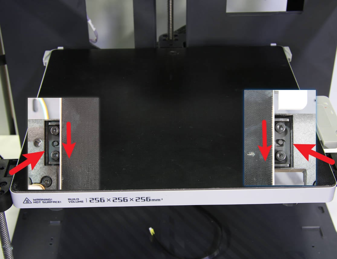
Install the heat bed on the 3 Z-sliders, move the heat bed as far forward as possible, and lock in 6 screws.
 |
 |
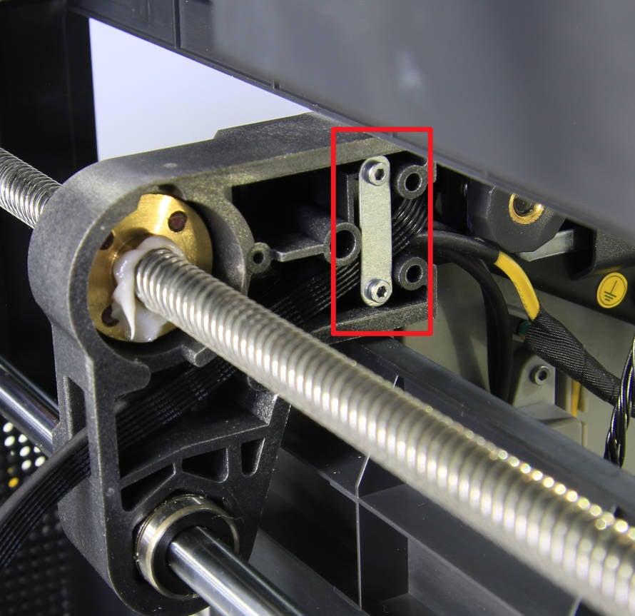
¶ Step 5 - Pass through the heat bed cables, lock the holding plate
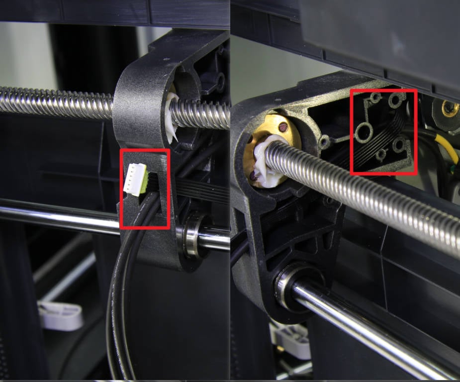
Put the printer on its right side, pass the heat bed signal cable through the cable hole on the rear slider, arrange the cables and press them into the cable groove of the rear slider, then install the cable holding plate, and lock in 2 screws.
 |
 |
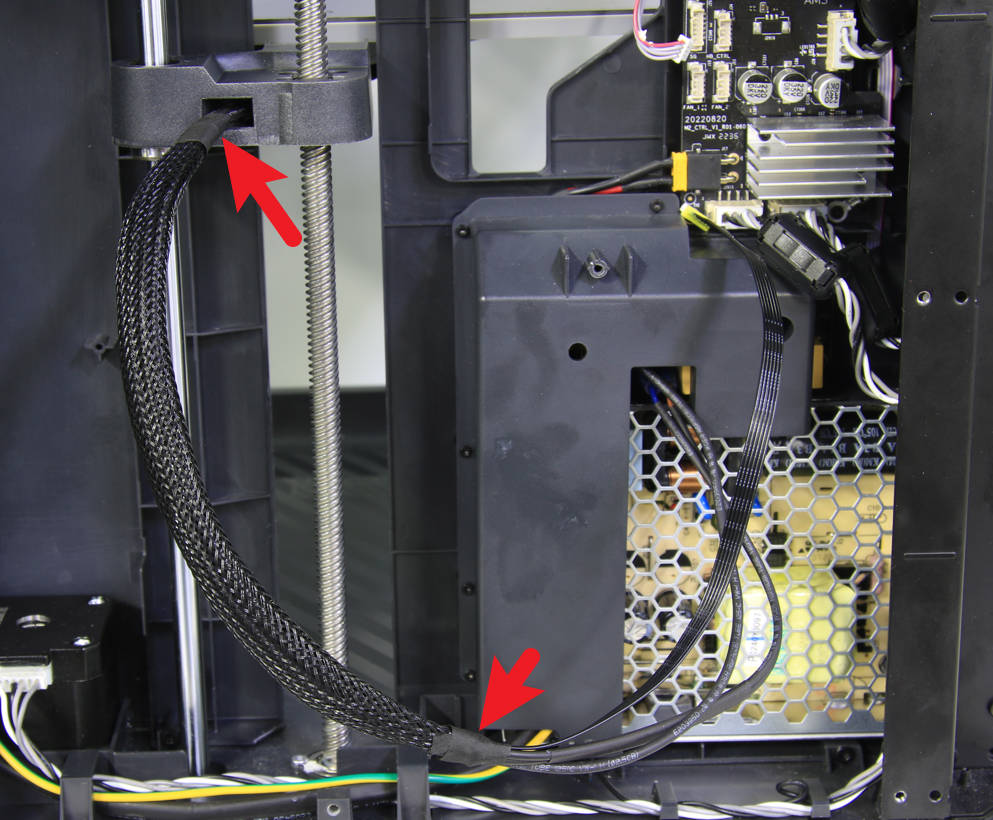
¶ Step 6 - Secure the cable mesh
Put the printer upright, pass the heat bed signal cable through the cable mesh, then wrap tape on both ends of the mesh to fix it, and place the cables to the cable buckle that attached on the column.
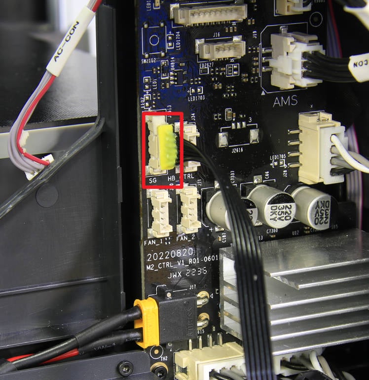
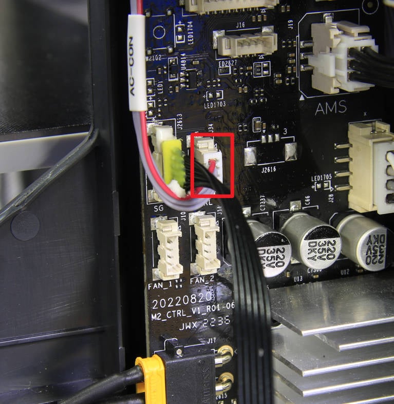
¶ Step 7 - Connect the signal cable to MC board
Connect the heat bed signal cable to the corresponding connector on the MC board, enhance the connector with silicone glue, and then connect the MC-AC connection cable.
 |
 |
¶ Step 8 - Install the cable railing
Install the cabe railing to the cable cover and lock in 2 screws with an H2.0 hex key.

¶ Step 9 - Install the excess chute and rear panel
Refer to the related contents of the Excess chute and Rear panel to install the excess chute and rear panel.
¶ How to verify
Connect the power cord cable of the printer, turn on the printer, and run the device self-test process. If the self-test passes, the operation is successful.
