¶ What is the left panel
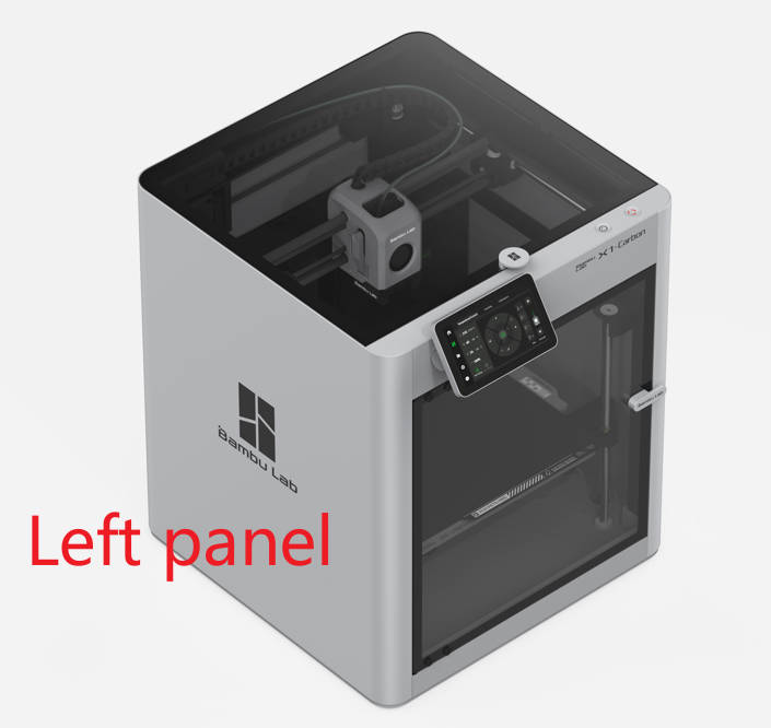
When facing the printer's front door, the left side cover is referred to as the left panel. The X1C utilizes a metal panel.
¶ When to use
Unacceptable deformation or damage on the left panel
¶ Tools and materials required
- A new left panel
- H2.0/1.5 hex key
¶ Safety warning and Machine state before starting operation
Before commencing the operation, ensure that the machine is switched off. If an AMS is connected, remove the PTFE tube and AMS buffer before proceeding.
Please also check the Old version information in this guide, if your printer uses the previous way of attaching the panel to the printer
¶ Video guide
¶ Operational guide(New version)
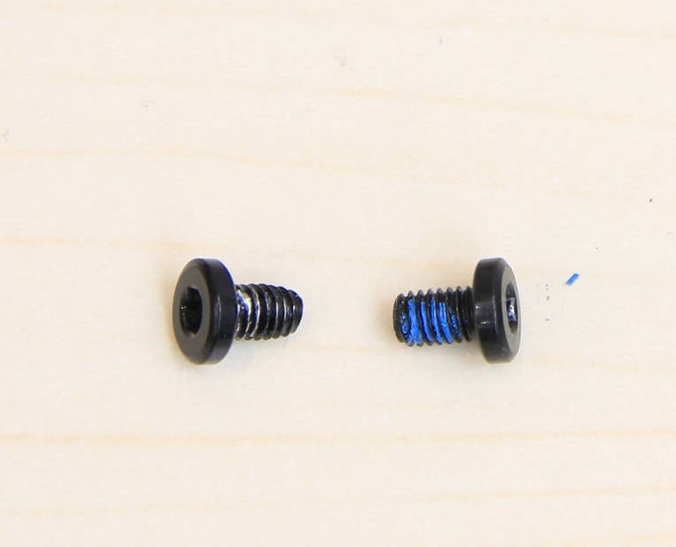
Precaution: The 2 screws on the bottom are different from the others.
¶ Step 1 - Remove the glass front door
Remove the upper glass cover plate, and then follow steps 1 to 3 of Replace the glass front door to remove the glass front door, as shown in the figure below.
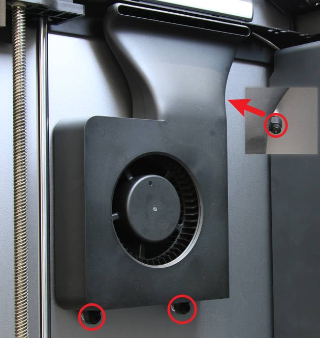
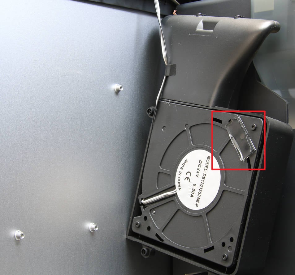
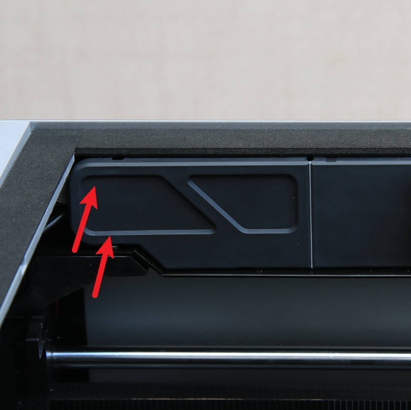
¶ Step 2 - Remove the auxiliary part cooling fan
Unscrew the 3 screws with the H2.0 hex key, and then detach the fan from the left panel.
 |
 |
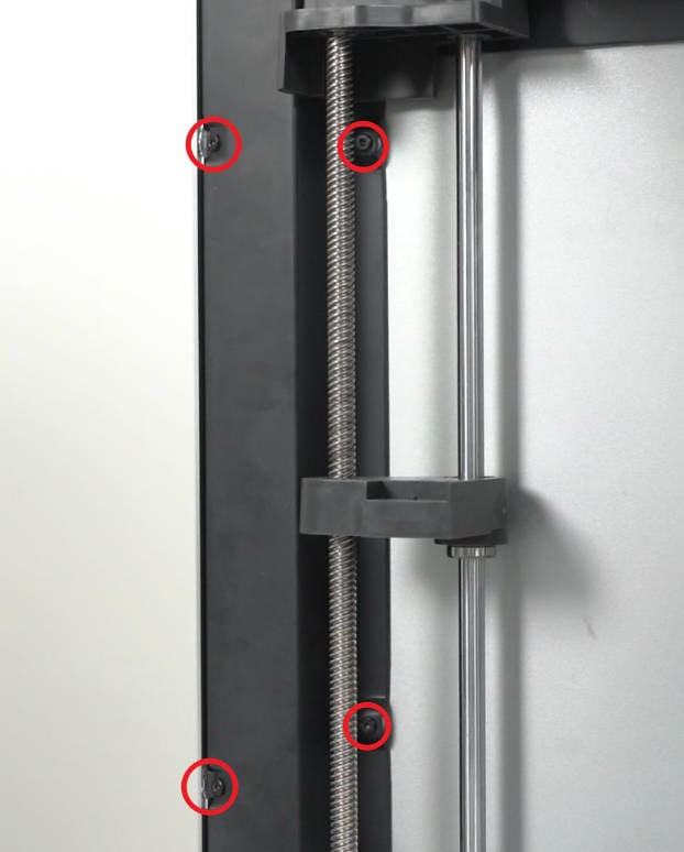
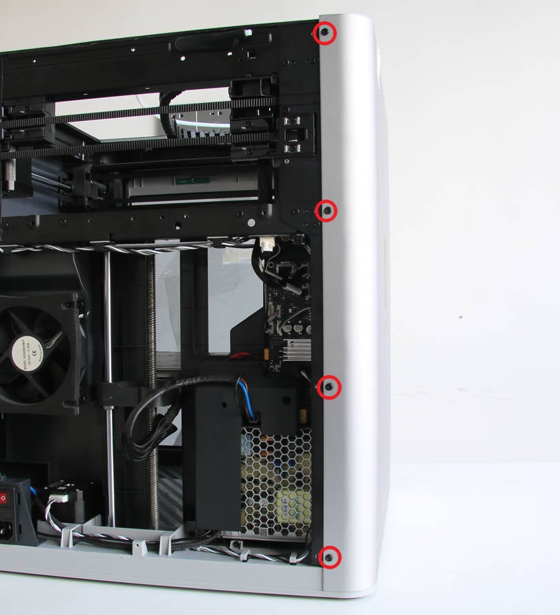
¶ Step 3 - Remove the front pillar screws
Remove the 4 screws on the front pillar using the H2.0 hex key.
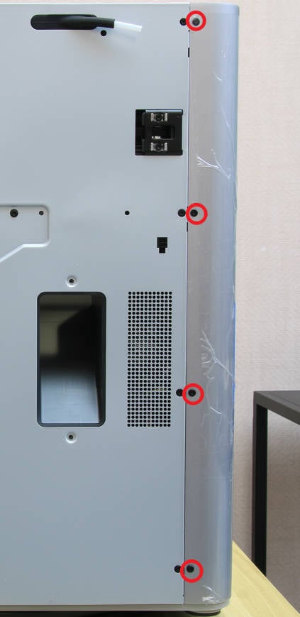
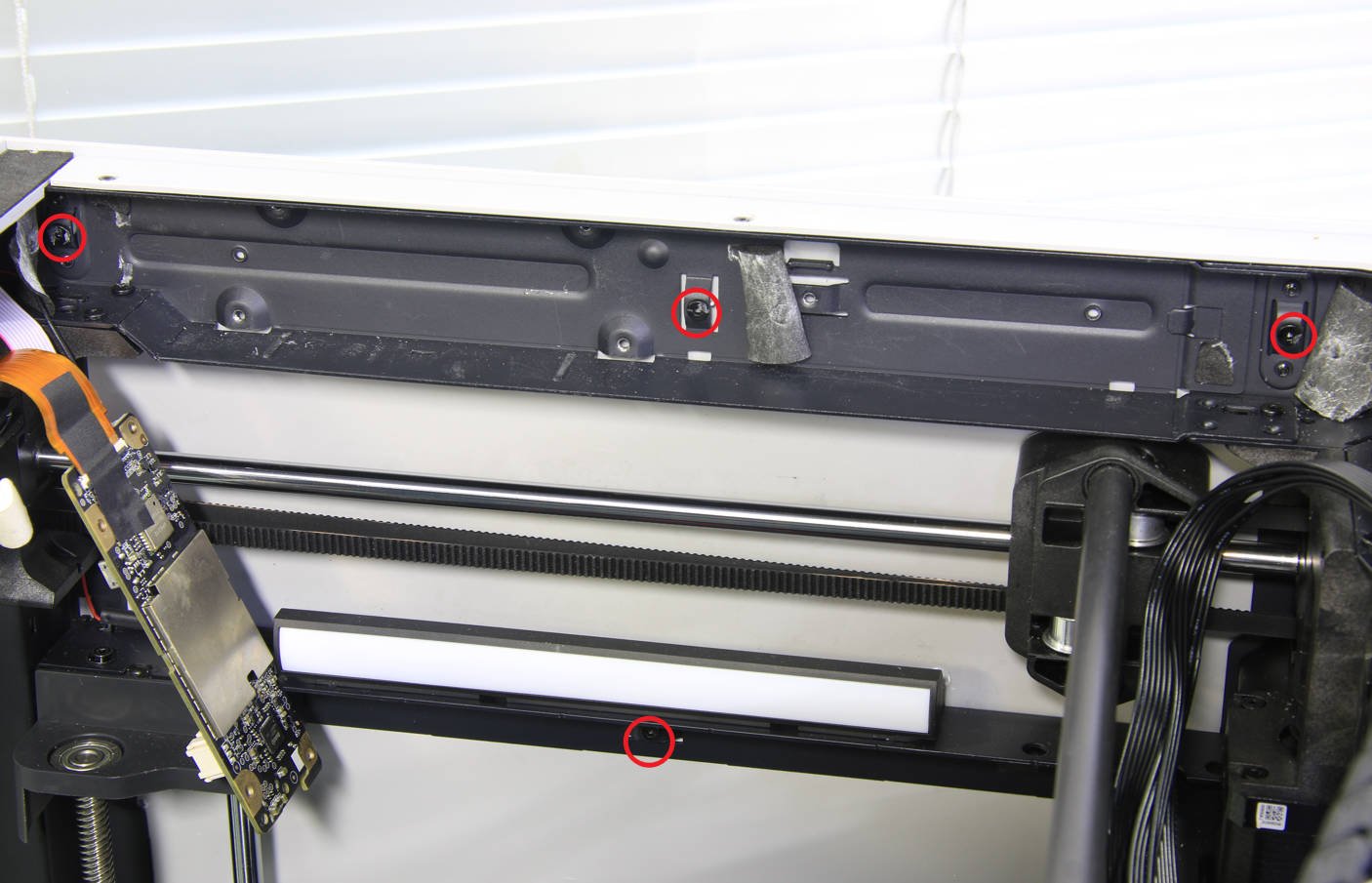
¶ Step 4 - Remove rear screws
Remove the 4 screws on the rear part of the panel using the H2.0 hex key.
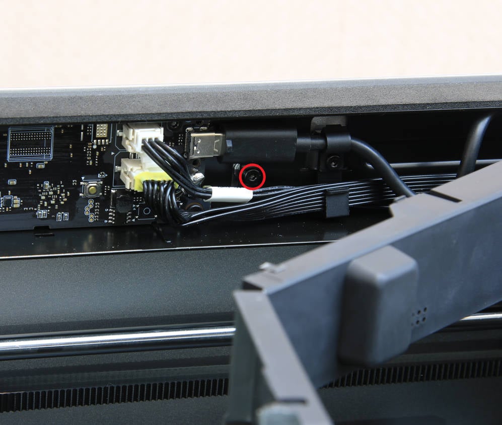
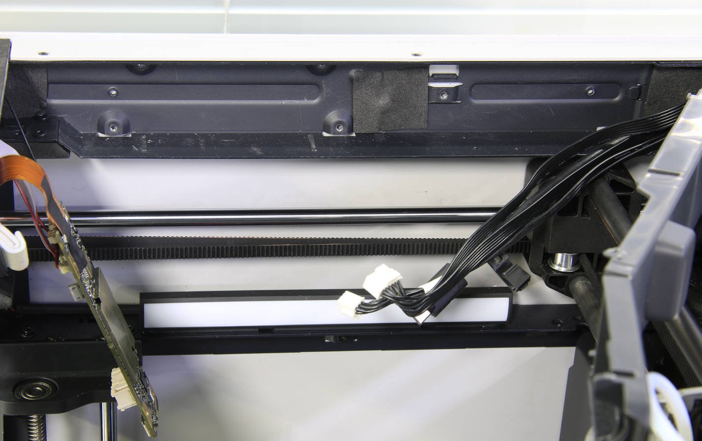
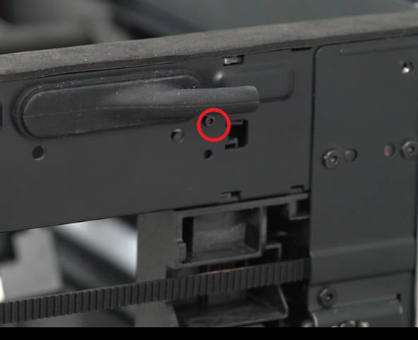
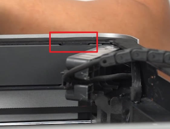
¶ Step 5- Remove the screw on the upper beam
Open the AP board cover to find the screw in the middle of the upper beam, and remove it using an H2.0 hex key.
 |
 |
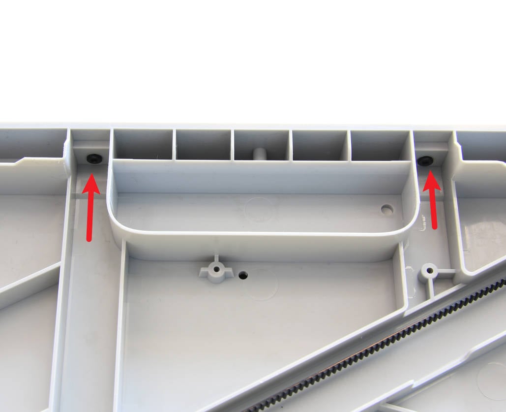
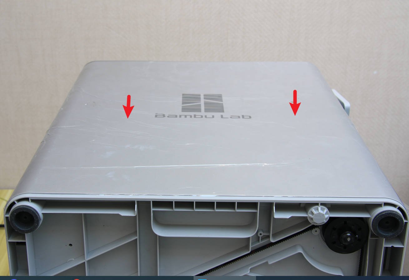
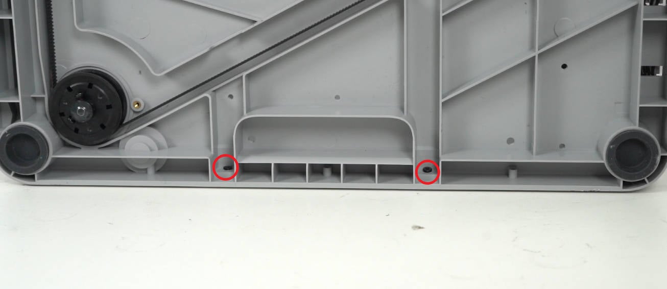
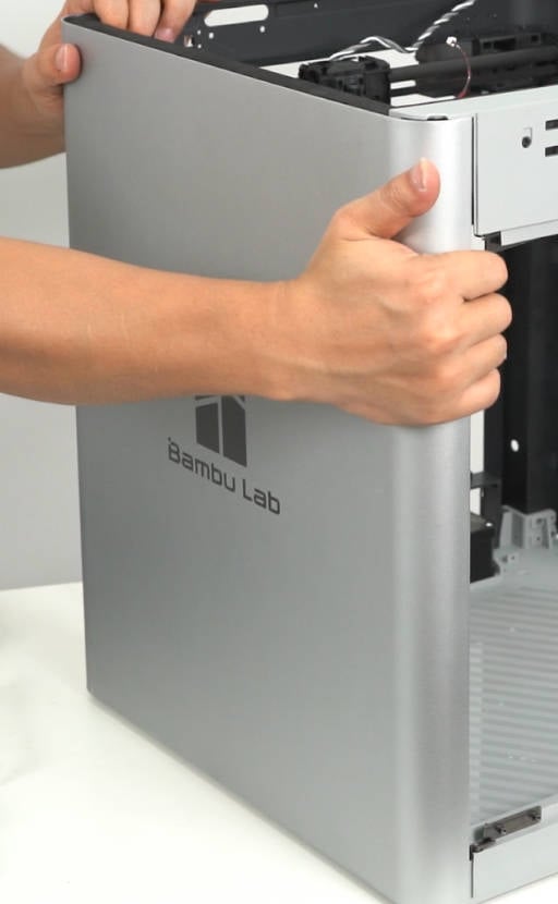
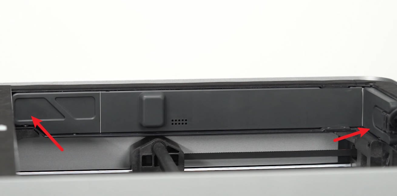
¶ Step 6 - Remove the bottom screws, and take off the left panel
Place the printer on its side, with the left panel facing up. Remove the 2 screws using an H2.0 hex key, and then take off the left panel. Please be cautious while handling the printer on its side, as the auxiliary part cooling fan is in a loose state.
¶ Step 7 - Install the left panel and secure the bottom screws
Install the left panel onto the printer, ensuring it is properly in place, and then secure it with 2 screws.
 |
|
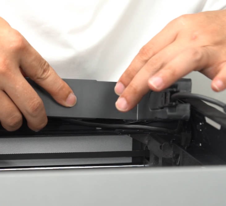
¶ Step 8 - Secure the screw on the upper beam
Secure 1 screw in the middle of the upper beam, and close the AP board cover.
|
|
 |
¶ Step 9 - Secure the front pillar screws
Secure the 4 screws on the front pillar.
¶ Step 10 - Secure rear screws
Secure 4 screws on the rear of the right panel.
¶ Step 11 - Install the auxiliary part cooling fan
Install the auxiliary part cooling fan and secure it with 3 screws.
Note: If the adhesive between the fan and the left panel is damaged during disassembly, you can use heat-resistant double-sided tape to apply it.
¶ Step 12 - Install the Glass front door
Please follow steps 4 to 6 to Replace the glass front door to install the glass front door, and then place the upper glass cover plate back in position.
¶ Operational guide(Old version)
¶ Step 1 - Remove the glass front door
Please refer to steps 1 to 3 of Replace the glass front door to remove the glass front door, as shown in the figure below.
¶ Step 2 - Remove the AP board
Please refer to steps 1 to 5 of Replace the AP board to separate the PA board from the chamber frame, as shown in the figure below.
¶ Step 3 - Remove the auxiliary part cooling fan
Please refer to Steps 1 to 4 of Replace the auxiliary part cooling fan to remove the auxiliary cooling fan.
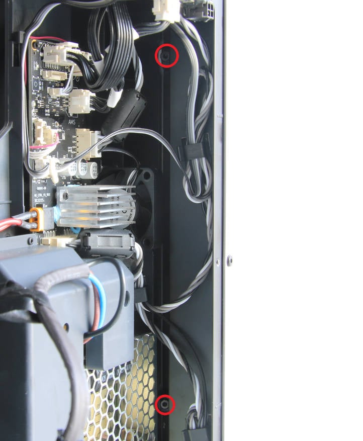
¶ Step 4 - Remove the AP board protective cover
Remove 1 screw on the back of the printer with the H1.5 hex key and remove the AP motherboard protective cover.
 |
 |
¶ Step 5 - Remove the left panel
After the previous series of operations, we finally reached the topic.
The light metal panel of the old version is fixed with a total of 16 screws, of which the 4 screws at the back are different from the other 12 screws. Refer to the picture below to find the screws in the corresponding positions and remove them one by one, then remove the light panel.
Note: X1 can refer to this version for processing, but the screws will be different due to different materials.
¶ Step 6 - Install the left panel
Install the left panel on the printer, making sure it is in place.
¶ Step 7 - Secure left panel screws
All screws should be secured according to the actual version. Please refer to the picture below for the screw-locking sequence. Note that the rear 4 screws are different from those in other positions, so don’t make a mistake.
¶ Step 8 - Install auxiliary cooling fan (for X1C, only rear panel for X1)
Please refer to Steps 5 to 8 of Replace the auxiliary part cooling fan to install the auxiliary part cooling fan.
¶ Step 9 - Install the AP board
Please refer to Steps 9 to11 of Replace the AP board to install the AP board and cables.
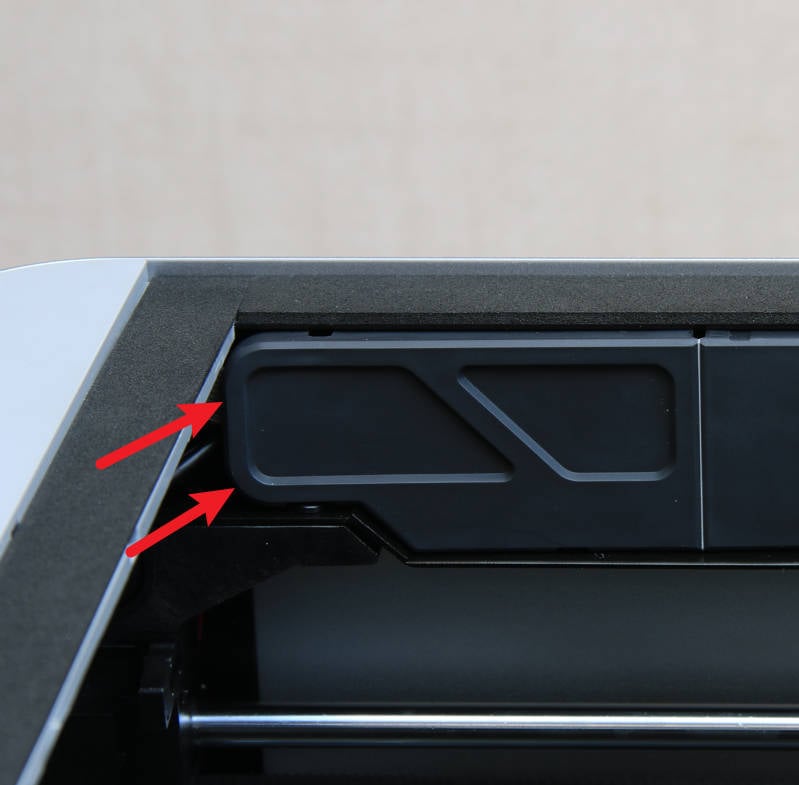
¶ Step 10 - Install the AP board protective cover
First, install the gap shown in the figure below, then install the entire AP board protective cover in place, and then secure a screw with the H1.5 hex key on the back of the printer.
|
|
|
¶ Step 11 - Install the Glass front door
Please refer to Steps 4 to 6 of Replace the glass front door to install the glass front door.
¶ To verify completion/success
1. Visually inspect the appearance and ensure that the right panel is correctly installed in place.
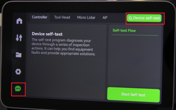
2. Connect the power cord and turn on the printer. Perform a Device self-test operation as shown below and verify that no errors occur.
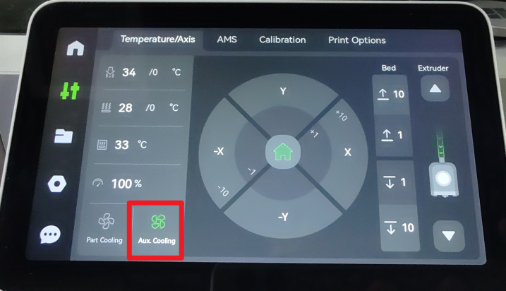
3. Operate the screen to activate the auxiliary part cooling fan. Confirm that the label turns green, and that the fan operates as expected.
If you encounter any issues, please retrace your steps and double-check the connections. If issues persist, contact the support team for further assistance.