¶ Phenomenon
1. The printer is ON and idle, but the tool head fails to move along X and Y axes when pressing the directional buttons (Rx exception);
2. There is no temperature information on the screen, both the hot end and the heat bed temperature are displayed as "0" (Tx exception);
3. Both the tool head movement and the temperature are abnormal (Rx & Tx exception).
¶ Causes & Solutions
1. Components on the AP board may be damaged and need to be replaced.
2. The MC board may be faulty and need to be replaced.
3. There may be poor connection on the MC-AP cable, which requires reconnecting or replacing the MC-AP cable.
¶ Safety warning and Machine state before starting operation
IMPORTANT!
It's crucial to power off the printer before performing any maintenance work on the printer and its electronics, including tool head wires, because leaving the printer on while conducting such tasks can cause a short circuit, which can lead to additional electronic damage and safety hazards.
When you perform maintenane or troubleshooting on the printer, you may be required to disassemble some parts, including the hotend. This process can expose wires and electrical components that could potentially short circuit if they come into contact with each other or with other metal or electronic components while the printer is still on. This can damage the electronics of the printer and cause further damage.
Therefore, it's essential to switch off the printer and disconnect it from the power source before doing any maintenance work. This will prevent any short circuits or damage to the printer's electronics. By doing so, you can avoid potential damage to the printer's electronic components and ensure that the maintenance work is performed safely and effectively.
If you have any concerns or questions about following this guide, open a new ticket in our Support Page and we will do our best to respond promptly and provide you with the assistance you need.
¶ Tools needed
- H2.0 hex key
- Multimeter
- Tweezers
¶ Operation guide
¶ Step 1 - Confirm the fault phenomenon
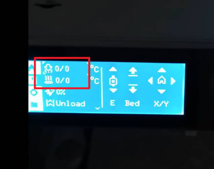
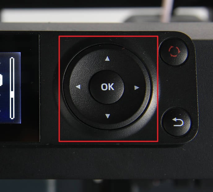
When the printer is turned on and idle, check the temperature information on the screen and the control of the toolhead movement to see whether the printer is RX abnormal, TX abnormal, or both RX and TX are abnormal, and then proceed to the next step.
 |
 |
¶ Step 2 - Check the status of the MC board
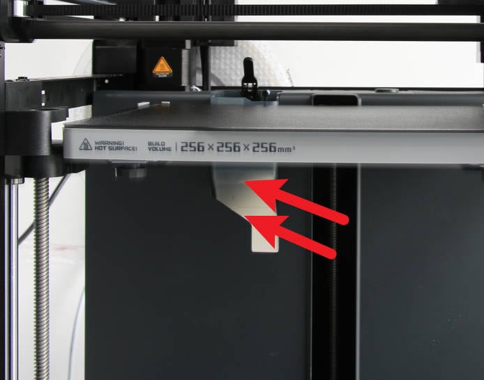
If the situation confirmed in step 1 is that both RX and TX are abnormal, you can keep the power on and observe the status indicator LED of the MC board through the excess chute (in case of uncertainty, you can remove the rear panel first, and directly observe the indicator LED status). If the indicator LED of the MC board flashes normally, you can proceed to the next step; If the MC board indicator does not work, it is recommended to replace the MC board.
(Click MC board to learn how to replace MC board)
¶ Step 3 - Pre-inspection of poor contact of AP-MC cable
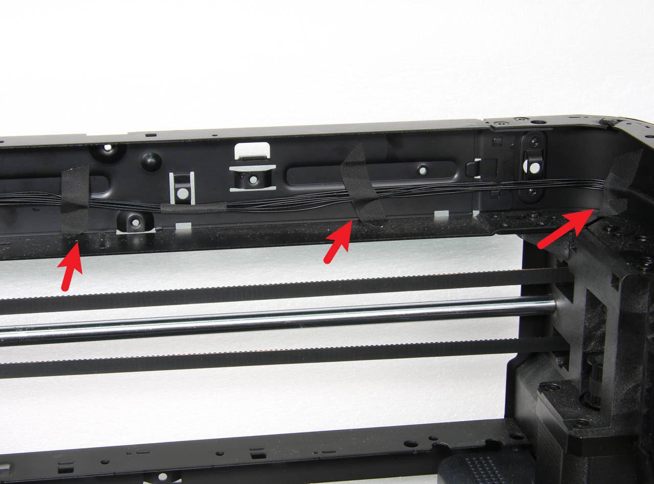
If Tx is abnormal (no temperature), you can continue to remove the fixed tape of the AP-MC cable under the power-on state, and then shake the entire cable to observe whether the temperature on the screen changes. If there is no change, proceed to the next step; If there is any change, it indicates a poor connection, and you can go to step 5.
¶ Step 4 - Check the AP board
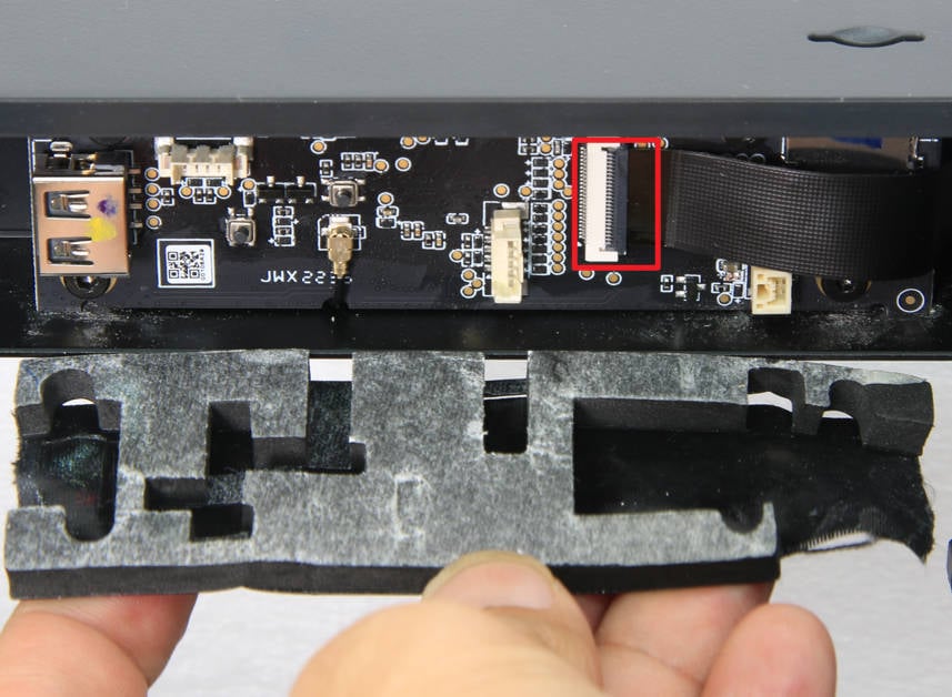
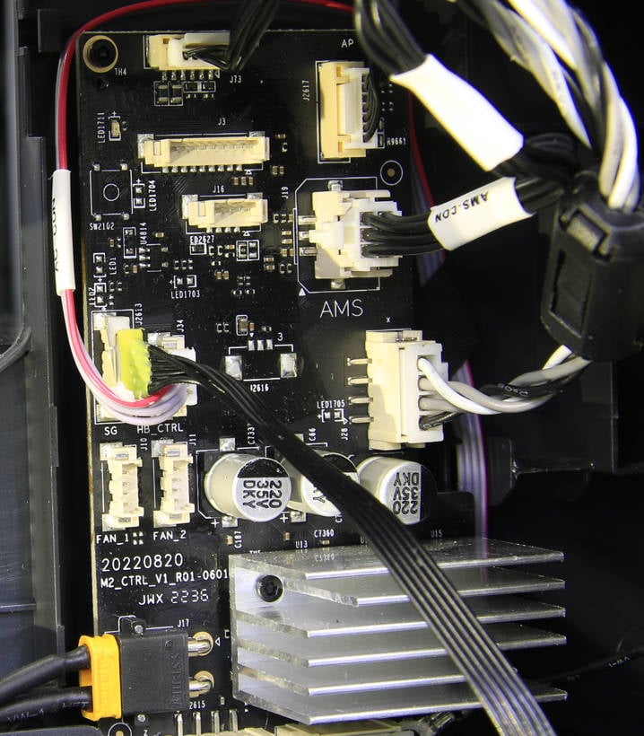
Remove the foam covering from the AP board, disconnect the camera connection cable, check the status of the components under the card slot, and confirm that there is nothing missing or burnt. If there are any, replace the AP board. If there are no abnormalities, proceed to the next step.
 |
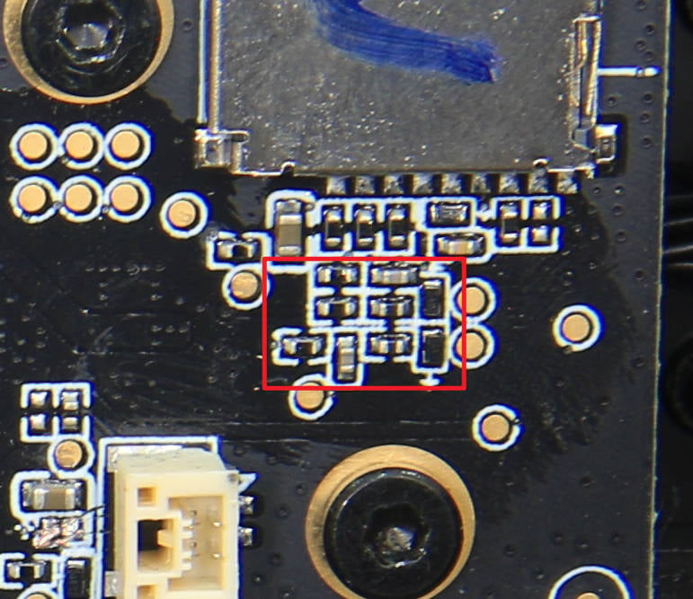 |
(Click AP board to learn how to replace the AP board)
¶ Step 5 - Check the connectors
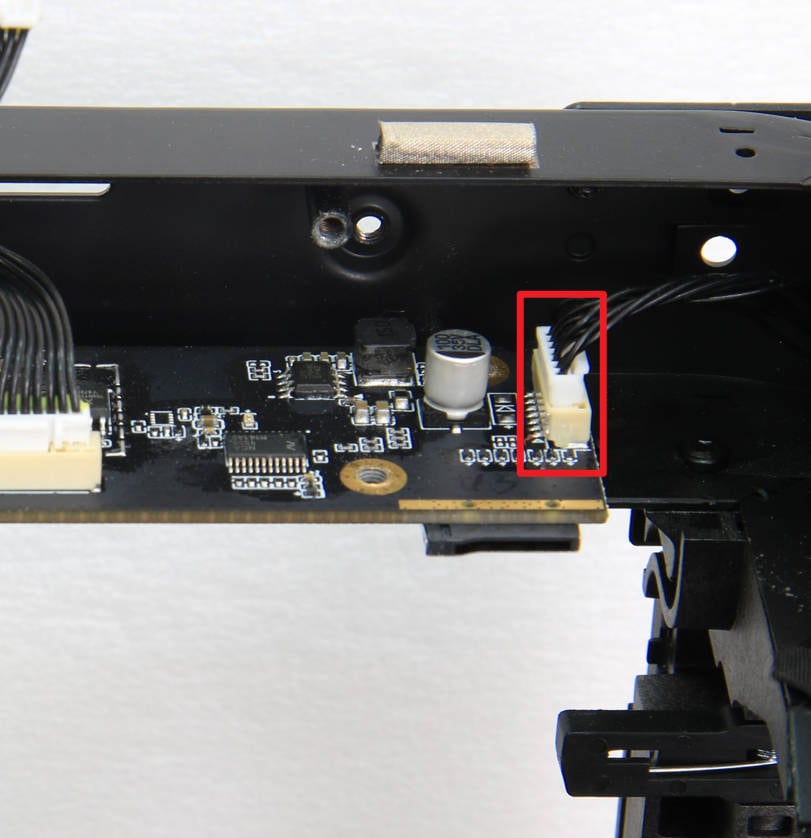
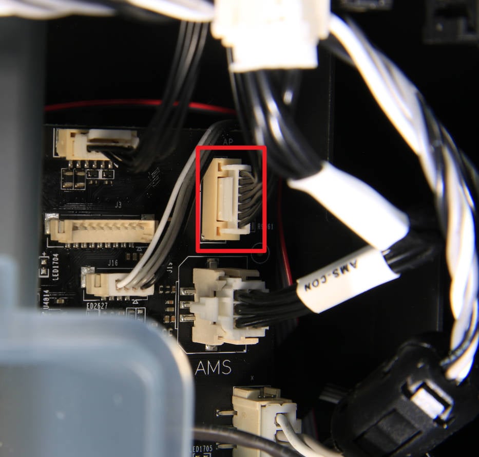
Refer to the relevant steps of the MC-AP cable, find the connectors of the cable on the AP board and MC board, confirm that the connection status is normal, unplug the plug, and check and confirm that the plugs and seats are normal and without damage. Then proceed to the next step.
 |
 |
¶ Step 6 - MC-AP cable connection continuity test
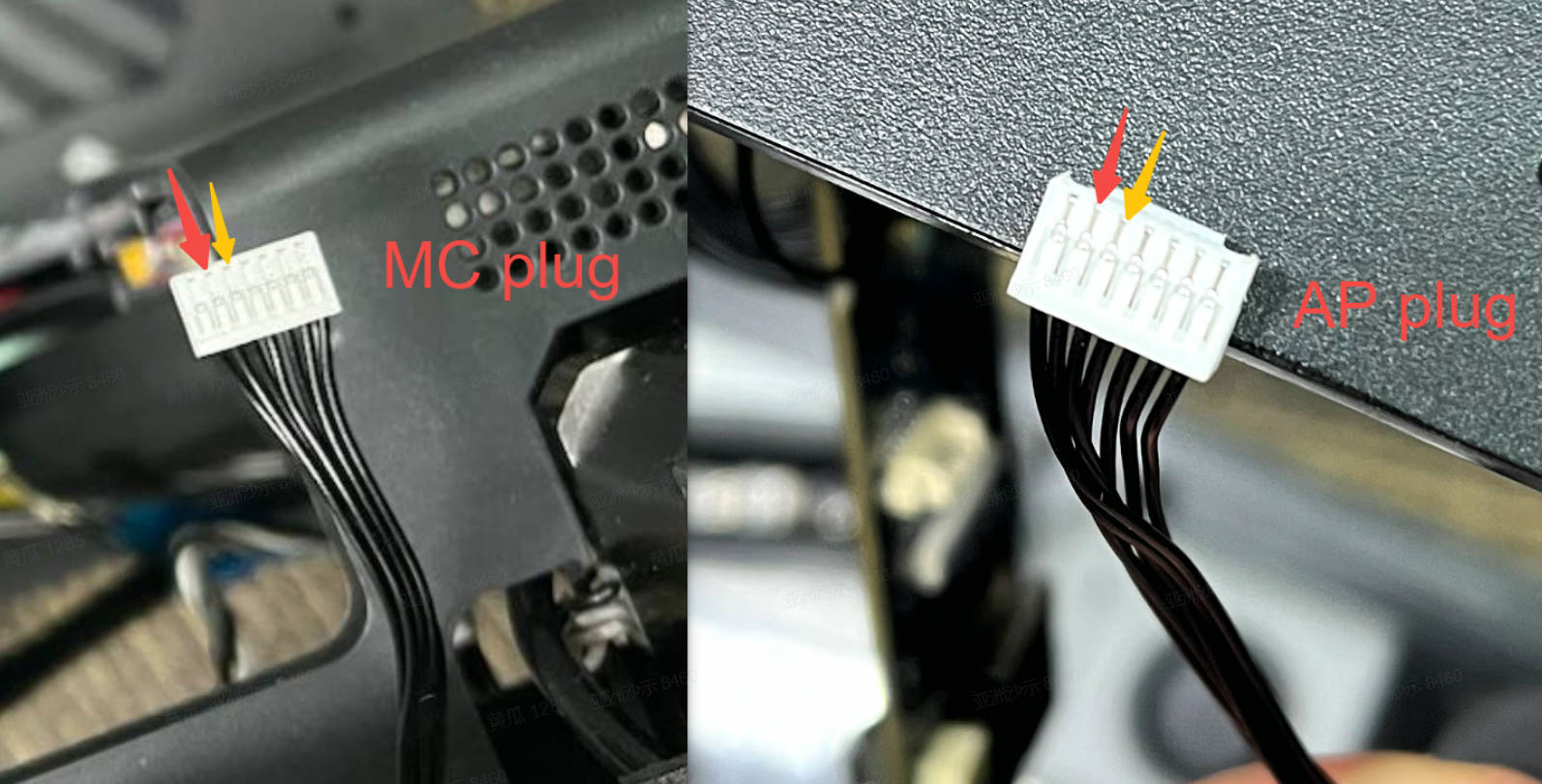
Use a multimeter to measure whether the second and third contact of the AP plugs (red points and yellow points below, respectively) are conductive. If you can detect conductivity across the red points and across the yellow points, proceed to the next step. If there is a break in conductivity across either set of points (red or yellow), replace the cable.
¶ Step 7 - Check the MC board
If no abnormality is found in the above steps, and the indicator of the MC board has been confirmed to work normally in step 1, you can try to observe whether there are any damaged components visible on the MC board. If you find any, replace the MC board. If you cannot find any damage, please provide the LOG file to the service team for analysis and confirmation. You could also check the MC-TH cable (this should be another troubleshooting guide).
¶ End Notes
We hope that the detailed guide we shared with you was helpful and informative.
We want to ensure that you can perform it safely and effectively. If you have any concerns or questions regarding the process described in this article, we encourage you to reach out to our friendly customer service team before starting the operation. Our team is always ready to help you and answer any questions you may have.
Click here to open a new ticket in our Support Page.
We will do our best to respond promptly and provide you with the assistance you need.