¶ Preface
During laser processing, smoke is generated. The laser air pump provides high-pressure airflow when the laser is in operation, which is used to blow away the smoke and dust produced during the cutting process. This not only prevents the cutting edges of materials from being blackened by smoke and reduces the risk of fire, but also protects the laser head lens from smoke and dust contamination. When used in conjunction with the Automatic Top Vent, Filter Switch Flap, Chamber Exhaust Fan, Automatic Exhaust Grille, exhaust pipe adapter, and exhaust pipe, the smoke generated by laser cutting will be discharged out of the printer chamber through the printer's exhaust fan. For more exhaust pipe installation guidelines, please refer to the relevant document. Laser Module Installation Guide (Taking 10W Laser Module as an Example)
Although most of the smoke will be discharged through the exhaust pipe, some smoke will still remain inside the chamber. Therefore, if a laser module is used, the internal contamination of the printer will be more severe than when only the printing function is used, requiring more frequent maintenance.
If the inner walls around the chamber are not cleaned for a long time, dirt will easily accumulate, and attachments on the front door and side panels may affect visibility. Therefore, it is also necessary to regularly wipe these areas with alcohol and non-woven fabric. At the same time, components such as the cooling fan air duct on the Toolhead, Flow Blocker, and its magnet bracket should be cleaned regularly. In addition, the X-axis Linear Guideway, Y-axis and Z-axis Linear Rods, and Lead Screws also need to be cleaned regularly with alcohol and non-woven fabric. It is particularly important to note that after wiping metal bearing components with alcohol, it is recommended to replenish Lubricant Oil (for Linear Guideways and Linear Rods) or Lubricant Grease (for Lead Screws).
To ensure the normal operation of various intelligent visual detection and sensor detection functions, it is very important to regularly clean the surfaces of various camera lenses and Flame Sensors. It is recommended to wipe the lenses with alcohol and non-woven fabric, and at the same time clean the laser wrench marks, Hotend marks, Build Plates, Laser Base marks, as well as the parallelogram limit blocks on the inner side of the Heatbed to prevent image blurring or mark recognition errors. When cleaning the camera, dip a small amount of alcohol on the non-woven fabric and wring it out slightly before wiping to prevent alcohol from seeping into the interior of the plastic housing. For an introduction to the intelligent detection function, please refer to the relevant document Introduction to H2D Intelligent Detection
In addition, components related to air exchange between the chamber and the outside are prone to dust accumulation. It is recommended to regularly clean the accumulated dust with a cleaning brush. The filter cover and the Exhaust Grille on the back can also be removed for cleaning to ensure the normal operation of the equipment and extend its service life.
¶ Maintenance Frequency
The H2S can evaluate the pollution level of the printer based on the task type and task duration, and provide corresponding cleaning and maintenance reminders. It is imperative to maintain and clean the Laser Module and various components of the printer as required. Failure to clean them on time may cause equipment damage and pose safety risks.
For the maintenance guide of the Laser Module, please refer to 10W Laser Module Regular Maintenance Recommendations
If only the 3D printing function is used, the maintenance frequency of each component is as follows:
| Component | Cleaning & Maintenance Frequency | Notes | Component | Cleaning & Maintenance Frequency | Notes |
|---|---|---|---|---|---|
| Printer Exterior & Screen | Every 3 months | X-axis Linear Guideway | Every 1 month | Apply Lubricant Oil after cleaning | |
| Heatbed | Every 3 months | Y-axis Linear Rod | Every 3 months | Apply Lubricant Oil after cleaning | |
| Toolhead | Every 3 months | Z-axis Lead Screw & Linear Rod | Every 3 months | Apply Lubricant Grease after cleaning | |
| Toolhead Camera | Every 3 months | Dip a small amount of alcohol on non-woven fabric and wring it out | Live View Camera | Every 3 months | Dip a small amount of alcohol on non-woven fabric and wring it out |
| Birds Eye Camera | Every 3 months | Dip a small amount of alcohol on non-woven fabric and wring it out | Enclosure Top Frame | Every 3 months | |
| Flame Sensor | Every 3 months | Dip a small amount of alcohol on non-woven fabric and wring it out | Left & Right Side Panels | Every 3 months | |
| Auxiliary Part Cooling Fan | Every 3 months | Activated Carbon Filter Cover | Every 3 months | ||
| Left & Right Inner Linings | Every 3 months | Exhaust Grille | Every 3 months | ||
| Chamber Exhaust Fan | Every 3 months | Extruder Gear | Every 3 months | Related to usage frequency and Filament type; cleaning can refer to this wiki |
¶ Materials Required for Cleaning

- Alcohol
- Cleaning Brush
- Lubricant Oil and Lubricant Grease (Lubricant Grease is available in bottled and bagged versions, depending on the version you receive)
- Non-woven Fabric or other lint-free cleaning cloth
- Gloves
¶ Cleaner Instructions
During the above maintenance process, it is recommended to use a small amount of alcohol (75% ethanol or 70% isopropyl alcohol) and non-woven fabric to wipe the surfaces of cameras, metals, and plastics. For special parts such as the filter cover, grilles, fan blades, and heat sinks, it is recommended to use a cleaning brush for cleaning.
After using liquid cleaners, wring out the non-woven fabric properly before cleaning. At the same time, it is strongly recommended that you increase the cleaning frequency to prevent oil stains from caking, which will be difficult to remove.
If the contamination is severe, oil stain cleaners such as Mr. Muscle can be used for deep cleaning.
¶ Maintenance and Replacement Instructions for Wearable Consumables
| Wearable Component | Recommended Replacement Frequency |
|---|---|
| Filament Cutter Blade | For regular Filaments such as PLA/PETG/ABS/PC, check the blade every 3-5 spools. Replace it if it becomes dull. For abrasive Filaments such as PA+CF/PA+GF, the blade will become dull quickly, so it is recommended to check after printing 1-2 spools of abrasive Filaments. Replace it if it becomes dull. |
| Extruder Gear | When you see a small amount of dust on the Extruder Gear, you should clean the dust inside the Extruder Unit. It is recommended to check and clean the Extruder Gear once a week. If wear on the Extruder Gear is found, it needs to be replaced. |
| Nozzle Wiper Silicone on Purge Wiper | If the Silicone Nozzle Wiper is damaged or deformed, it needs to be replaced to ensure the nozzle cleaning effect. |
| Hotend Silicone Sock | If there are signs of wear on the Silicone Sock, or if the Silicone Sock cannot be firmly fixed on the Hotend, the Silicone Sock should be replaced. |
| Hotend | Under normal circumstances, when printing non-carbon fiber Filaments such as PLA and PETG, it is recommended to perform cold pull cleaning on the Hotend after printing 5 spools of Filament; when printing carbon fiber Filaments, perform cold pull cleaning on the Hotend after printing 2 spools of Filament. If obvious wear on the Hotend is found causing Filament leakage, and regular cleaning cannot solve the problem, please replace it with a new Hotend. |
¶ Maintenance Steps
Before starting the cleaning and maintenance operations, please turn off the printer first.

¶ Cleaning of Components Related to Laser Module (If there is no Laser Module, skip the first 3 steps and start from Step 4)
¶ Step 1: Remove the Laser Base
Open the printer's front door, remove the top cover, and then take off the Laser Base from the Heatbed.
 |
 |
¶ Step 2: Clean the Laser Base and Support Bars
Put on gloves and remove all support bars from the Laser Base.
 |
 |
First, spray alcohol on the marks around the Laser Base and carefully wipe with non-woven fabric to clean the stains.

 |
 |
Then spray alcohol inside the Laser Base and carefully wipe with non-woven fabric.


Spray alcohol on the support bars and wipe with non-woven fabric to clean the stains. After cleaning, reinstall the support bars into the card slots of the Laser Base.


¶ Step 3: Remove the Laser Module
Disconnect the laser connection cable, unlock the quick-release latch, and remove the Laser Module.
 |
 |
¶ Overall Printer Cleaning (Related to 3D Printing Function)
¶ Step 4: Clean the Printer Front Door and Screen
Use non-woven fabric dipped in alcohol to wipe the printer screen, the outer side and inner side of the front door to clean the dust.


¶ Step 5: Clean the Heatbed
Spray alcohol on the Heatbed and wipe the Heatbed surface with non-woven fabric.


After wiping the Heatbed surface clean, continue to wipe the edges around the Heatbed to clean the stains, especially the Heatbed surface markers required for camera recognition.

¶ Step 6: Clean the Toolhead
Use a damp non-woven fabric dipped in alcohol cleaner to wipe the front, rear, left, and right surfaces of the Toolhead Middle Housing and the Filament Cutter Lever.
 |
 |
Remove the Toolhead Front Cover to clean the surface of the Extruder Unit.

Clean the Toolhead Camera and Part Cooling Fan.


Clean the Cable Chain and PTFE Tube Coupler.

¶ Step 7: Clean and Lubricate the X-axis Linear Guideway
Use non-woven fabric to wipe the X-axis Linear Guideway; the belt can also be cleaned at the same time. The Toolhead needs to be moved to ensure that the Linear Guideway on both the left and right sides of the Toolhead is cleaned thoroughly, and that the upper and lower ball grooves of the Linear Guideway are cleaned properly.
 |
 |
After cleaning all dust and foreign objects on the surface of the X-axis Linear Guideway, it is necessary to add Lubricant Oil to the rolling grooves of the Linear Guideway, and move the Toolhead left and right to distribute the Lubricant Oil evenly on the Linear Guideway. Please note that both the left and right sides of the Toolhead must be fully lubricated, and the upper and lower sides of the Linear Guideway need to be coated with Lubricant Oil.
 |
 |

¶ Step 12: Clean and Lubricate the Y-axis Linear Rod
Use non-woven fabric sprayed with alcohol to wipe the Y-axis Linear Rod, then move the Toolhead to clean the part of the Linear Rod blocked by the carriage.


After cleaning this section of the Linear Rod completely, apply Lubricant Oil on the Linear Rod. When applying, both the upper and lower sides need to be coated, and it is recommended to apply it in an "S" shape. Move the Toolhead back and forth to distribute the Lubricant Oil evenly on the Y-axis Linear Rod for full lubrication.

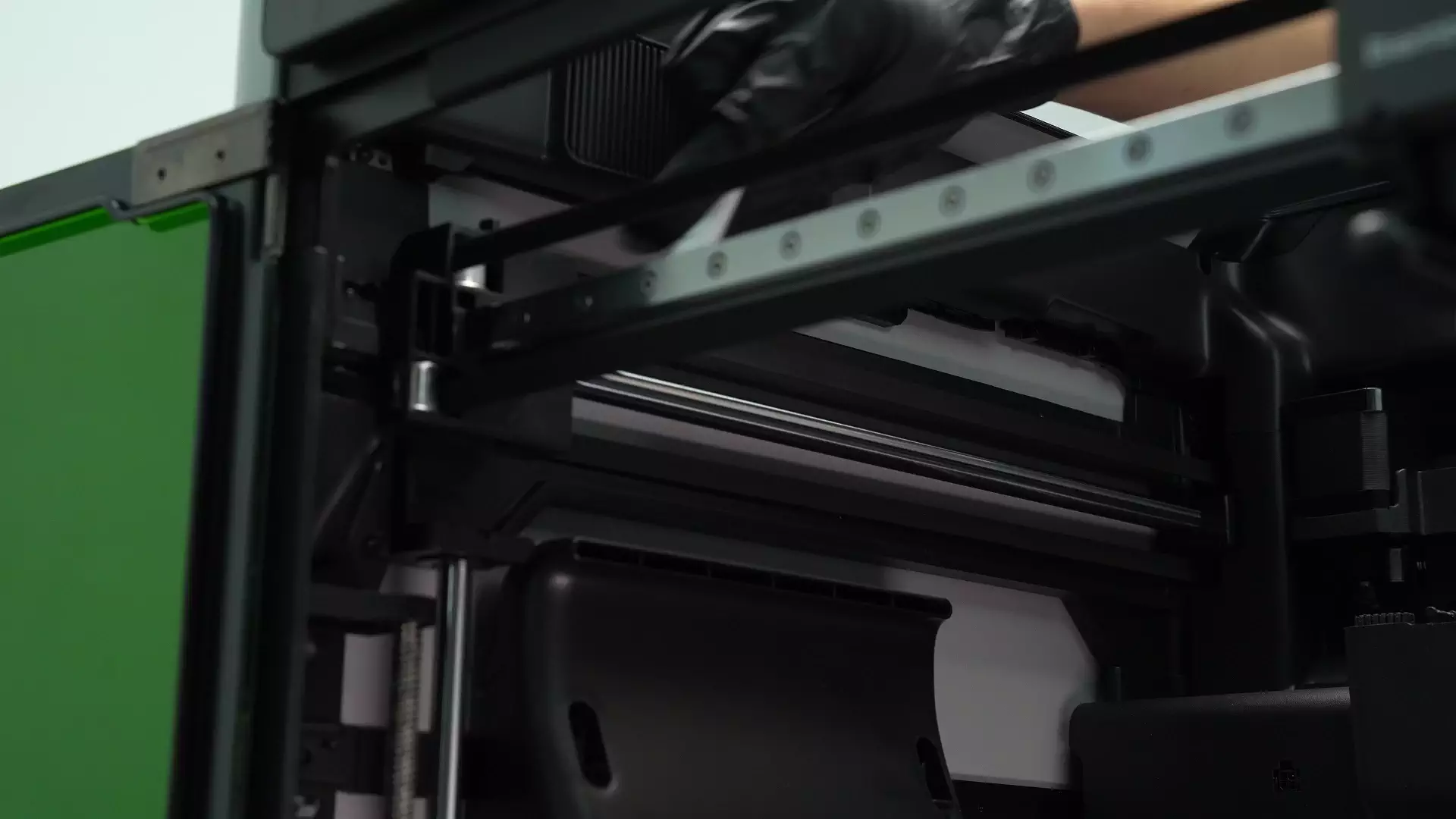
Next, clean and lubricate the other Y-axis Linear Rod using the same method.


¶ Step 14: Clean and Lubricate the Z-axis Lead Screw and Linear Rod
Wrap the Linear Rod with non-woven fabric dipped in alcohol and wipe it by moving it up and down to ensure the Linear Rod is clean. Then wipe the Lead Screw with the same motion.


Then apply Lubricant Grease on the Lead Screw and Lubricant Oil on the Linear Rod. Please note not to mix up Lubricant Oil and Lubricant Grease. The Lead Screw refers to the rod with threads, and the Linear Rod refers to the smooth rod. Lubricant Grease is thicker than Lubricant Oil.

 |
 |
In addition to the left Linear Rod and Lead Screw, there are also right and inner Linear Rods and Lead Screws inside the H2S, totaling 3 sets. The same cleaning and lubrication operations need to be performed on the other 2 sets of Linear Rods and Lead Screws.
The following figures show the cleaning and lubrication process of the right Linear Rod and Lead Screw.


The following figures show the cleaning and lubrication process of the inner Linear Rod and Lead Screw.


After lubrication is completed, power on the printer again and control the Heatbed to move up and down on the printer screen. The purpose is to allow the Lubricant Oil and Lubricant Grease to fully soak the Z-axis Lead Screw and Linear Rod to ensure sufficient lubrication.

 |
 |

Before continuing with the cleaning work, please turn off the printer again.

¶ Step 9: Clean the Flame Sensors
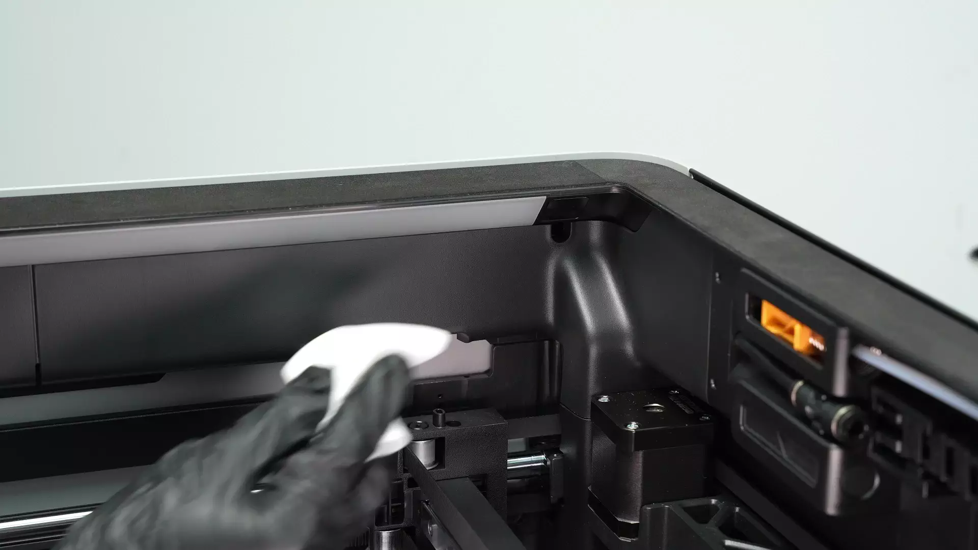
There are 4 Flame Sensors in the printer, located at the 4 corners of the Printer Frame. Wipe each Flame Sensor with non-woven fabric.

¶ Step 10: Clean the Birds Eye Camera and Live View Camera
Use non-woven fabric sprayed with alcohol to wipe the lenses of the Birds Eye Camera and Live View Camera.
 |
 |
 |
 |
¶ Step 11: Clean the Enclosure Top Frame, Left & Right Inner Linings, Inner Sides of Left & Right Side Panels, and Printer Bottom
Use non-woven fabric sprayed with alcohol to clean the inner lining of the Enclosure Top Frame, the inner linings of the left and right Side Panels (all sides need to be wiped), the upper sides of the left and right Inner Linings, and the surface of the left Inner Lining. At the same time, wipe the Purge Wiper to clean residual Filament. If some positions are difficult to clean, the Toolhead can be moved to facilitate cleaning.


Raise the Heatbed appropriately, then clean the dust and foreign objects at the bottom of the printer.

¶ Step 13: Clean the Auxiliary Part Cooling Fan
Use non-woven fabric dipped in alcohol to clean the dust on the glass of the left Side Panel and the upper side of the Auxiliary Part Cooling Fan, then wipe the surface and both sides of the Auxiliary Part Cooling Fan. There is a shock absorption structure on the upper side of the Auxiliary Part Cooling Fan; when cleaning, try not to pull it outward with force to prevent the shock absorption pins from falling off.


¶ Step 16: Clean the Activated Carbon Filter Cover
Clean the filter cover with a cleaning brush. If the filter cover is particularly dirty or the filter needs to be replaced, further cleaning can be done according to the method below.
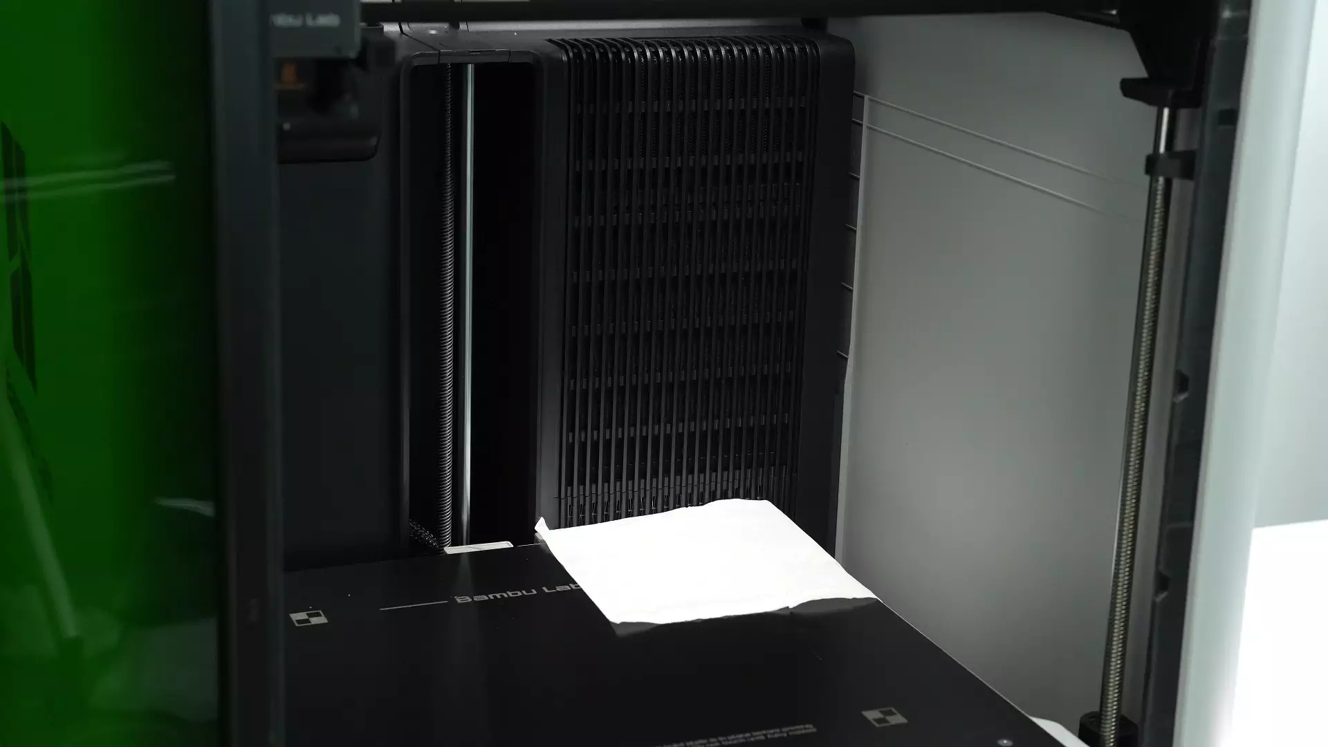
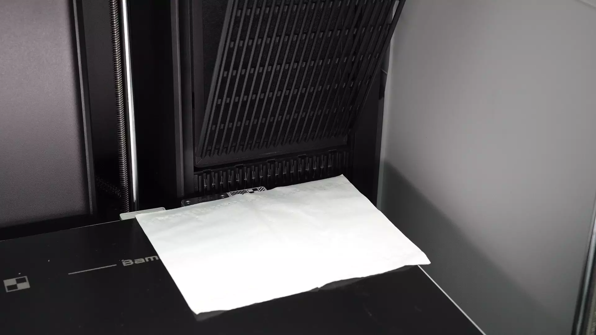
Press the top of the Activated Carbon Filter Cover with your hand and pull it outward to unlock the top buckle, then remove the Activated Carbon Filter Cover. When removing the Activated Carbon Air Filter, place paper under the Activated Carbon Air Filter to prevent dust from falling into the printer.
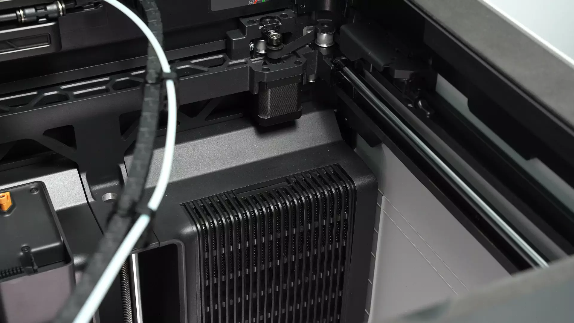


If the filter cover is particularly dirty, after removing it, first use a cleaning brush to clean the dust on both the front and back sides of the filter cover, then wipe the filter cover clean with non-woven fabric dipped in alcohol.


If the filter cover is extremely dirty and cannot be cleaned by ordinary methods, you can try rinsing the filter cover directly under the faucet while cleaning it with a cleaning brush. Please note that after washing with water, the filter cover must be completely dried. There are some electronic components around the filter cover, and residual moisture may affect the function of these electronic components.

¶ Step 17: Clean the Inner Side of the Chamber Exhaust Fan and Air Filter Slot
Use non-woven fabric dipped in alcohol to wipe the Activated Carbon Filter slot inside the right Inner Lining.
Move the Filter Switch Flap upward to clean the lower part of the flap. After cleaning, lower the Filter Switch Flap again. When cleaning the Filter Switch Flap, frequent upward and downward movement of the flap may reduce the service life of the steering gear, so try to minimize the number of times you push and pull the flap.


After cleaning, install a new Activated Carbon Air Filter into the right Inner Lining of the printer. Then insert the Activated Carbon Filter Cover obliquely into the Inner Lining, insert the five pins at the bottom into the Inner Lining, push the Activated Carbon Filter Cover inward, and snap the four buckles and one spigot at the top into the Inner Lining.


¶ Step 19: Clean the Exhaust Grille
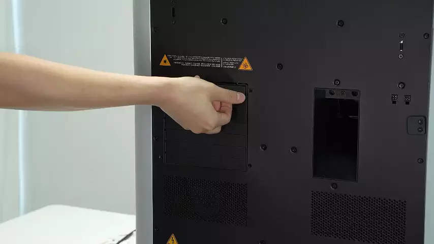
The Exhaust Grille is located on the outer side of the Chamber Exhaust Fan, with a total of 7 Exhaust Grilles. When removing the Exhaust Grille, remove it from top to bottom. First, slightly push the Exhaust Grille outward to concave it, then take out the positioning block on the right side from the small hole. Rotate the Exhaust Grille 90° clockwise, lift it up slightly to take out the pin, and remove the Exhaust Grille. Remove the remaining 6 Exhaust Grilles following the same steps.


First, use a cleaning brush to remove the dust on the Exhaust Grille, then wipe the Exhaust Grille with non-woven fabric dipped in alcohol.


If the Exhaust Grille is extremely dirty and cannot be cleaned by ordinary methods, you can try rinsing the Exhaust Grille directly under the faucet while cleaning it with a cleaning brush. Please note that after washing with water, the Exhaust Grille must be completely dried. There are some electronic components around the Exhaust Grille, and residual moisture may affect the function of these electronic components.

¶ Step 20: Clean the Outer Side of the Chamber Exhaust Fan
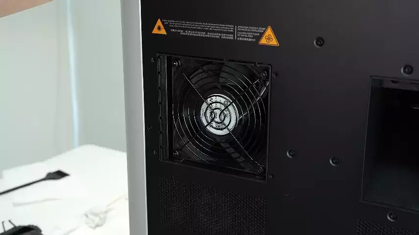
After removing the Exhaust Grille, use a cleaning brush to clean the dust on the outer side of the fan.

After cleaning, install the Exhaust Grille from bottom to top. Start from the left side first, insert the left pin into the hole indicated by the arrow, align the left positioning block with the small hole shown in the circle and snap it into place, then snap the right positioning block into the small hole on the right side. Install the remaining 6 Exhaust Grilles following the same steps.
 |
 |
 |
 |
¶ End Notes
We hope the detailed guide provided has been helpful and informative.
If this guide does not solve your problem, please submit a technical ticket, we will answer your questions and provide assistance.
If you have any suggestions or feedback on this Wiki, please leave a message in the comment area. Thank you for your support and attention!