¶ Issue Description
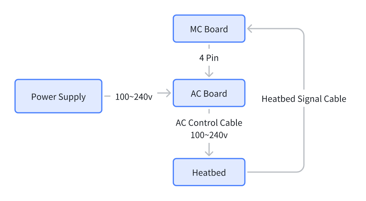
During the heatbed heating process, the printer strictly monitors the machine's internal state. When the printer detects that the heating status of the heatbed does not meet expectations (such as AC control cable disconnection, AC board failure, heatbed cable cracking, heatbed failure, etc.), the printer will stop heating to ensure system safety and display a message indicating a potential heatbed malfunction.
Possible reasons
-
The AC control cable is loose or disconnected
-
The AC board is damaged
-
The heatbed signal cable is cracked
-
The heatbed fails
¶ Troubleshooting
If this error occurs, please immediately stop using the printer and turn off the printer's power to ensure safety.
Safety warning
The heatbed is directly heated by mains electricity, and there is a danger of high voltage. It is necessary to ensure that troubleshooting is carried out with the power off.
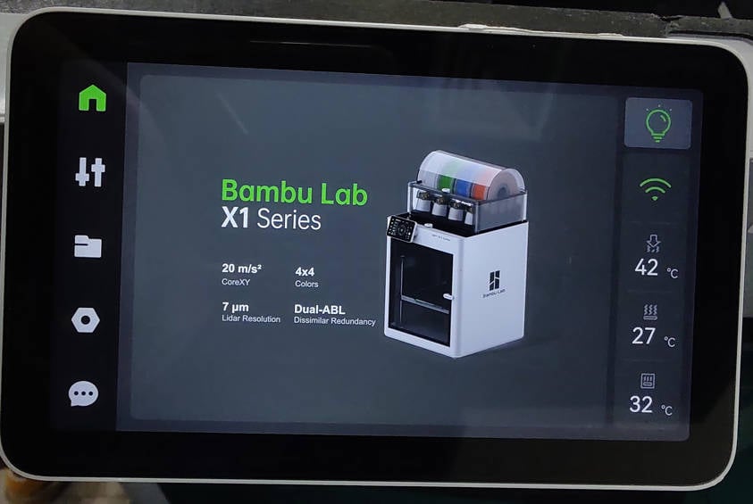
Set the heatbed to a middle height from the LCD screen when the printer is still powered on.
¶ Tools, Equipment and Materials
-
H2.0 Hex Wrench
-
H1.5 Hex Wrench
-
Phillips screwdriver
-
Tweezers
-
Multimeter
¶ Fault Isolation Process
-
Check the heatbed power cable and circuit board connections.
-
With the power off, use a multimeter to measure the heatbed resistance.
-
With the power on, check the AC board output (high voltage is dangerous; electrical proficiency is required).
¶ A1 Series
-
Replace the AC board
A1
For A1 mini, it is similar to replace the mainboard. -
Replace the MC board
For A1 mini, it is similar to replace the mainboard.
For A1 mini, it is similar to replace the mainboard.
¶ X1 & P1 Series
¶ Disassembly
¶ Step 1. Remove the rear cover screws
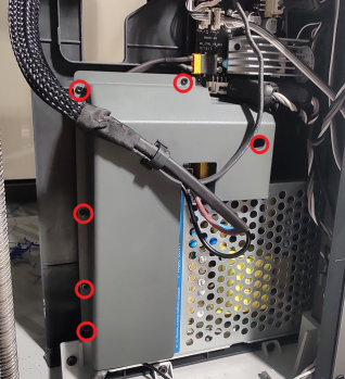
NOTE:
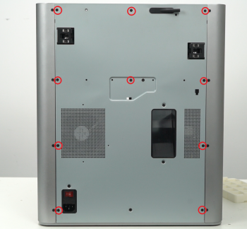
There are a lot of screws involved in this procedure. Please label them and group them in separate sections to avoid issues.
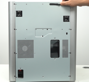
Remove the 10 screws and 4 screws from the rear cover shown in the picture. There are 2 types of screws, so keep them separate and remember which ones go where.
 |
 |
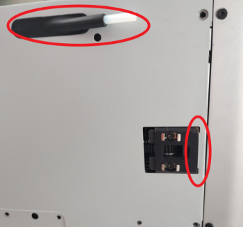
¶ Step 2. Remove the rear cover
Remove the rear cover by unlocking the left side belt tension port first, and then the right side one to avoid getting stuck.
 |
 |
¶ Step 3. Remove the excess chute
Remove 2 screws, and remove the excess chute.
 |
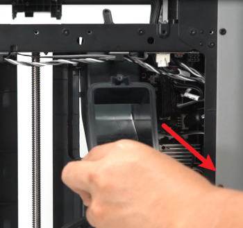 |
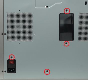
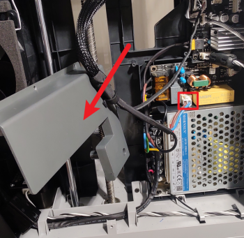
¶ Step 4. Remove the power module protective cover
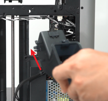
Remove the 6 screws shown, move the power module protective cover to the side, and disconnect the power cable of the heat bed from the AC power board.
 |
 |
¶ Inspection
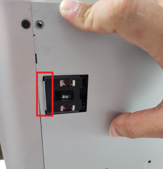
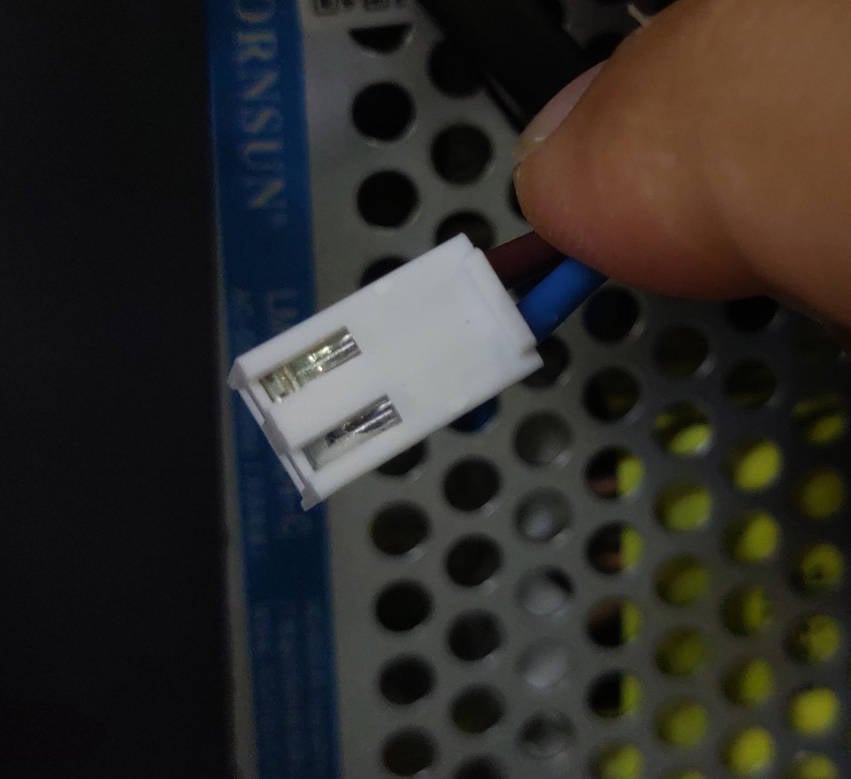
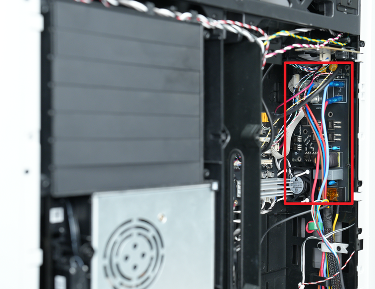
¶ Step 5. Check the 2PIN cable and its connection
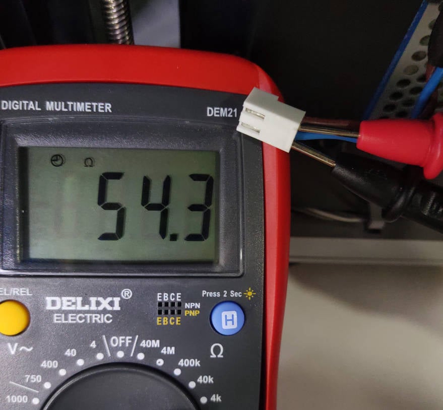
After confirming that the 2 pins are normal, reconnect the power cable to the AC power board. Temporarily connect the power cord to start the printer, and set the bed temperature to confirm whether the problem is solved. If not resolved, after disconnecting the power cord, proceed to the next step.
 |
 |
Reminder:
If you have a multimeter at home, you can also test the resistance value of the two pins. Under normal circumstances, the resistance value is about 50~60 ohms. If the resistance value is not displayed, the power connection at the heat bed end is likely open or the internal components of the heat bed are burned out.
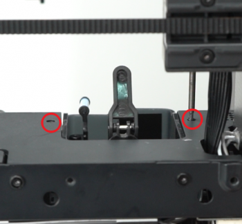
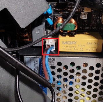
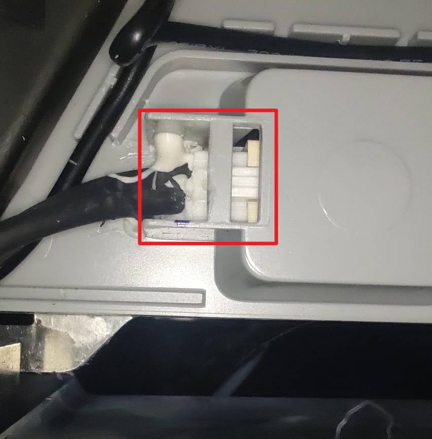
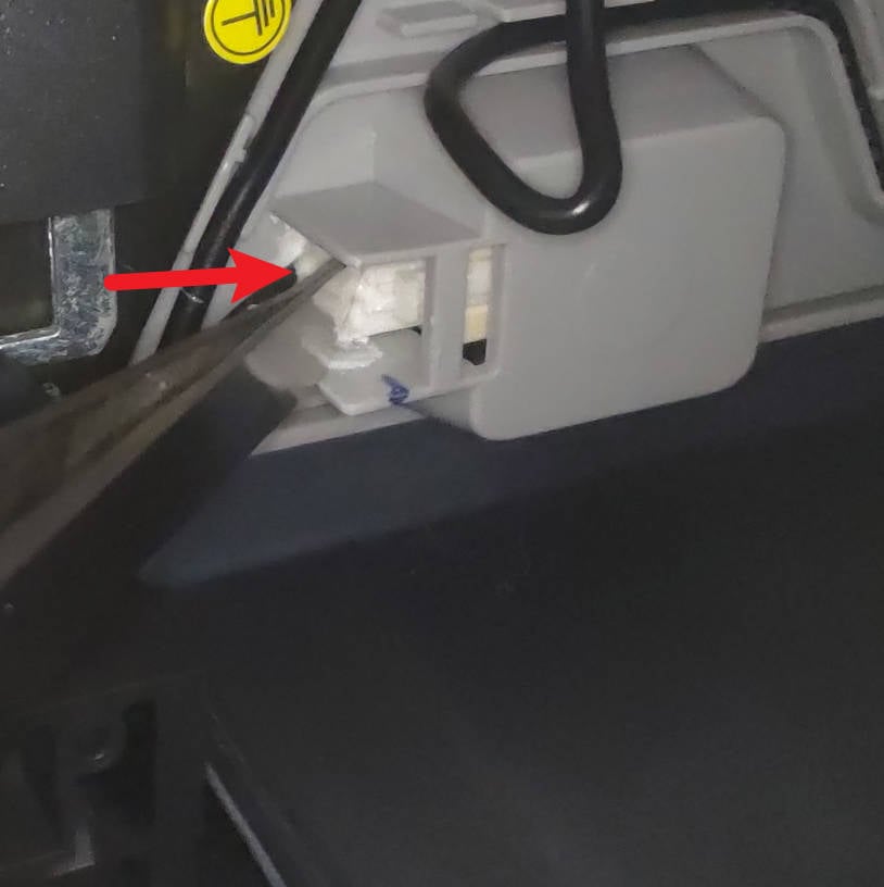
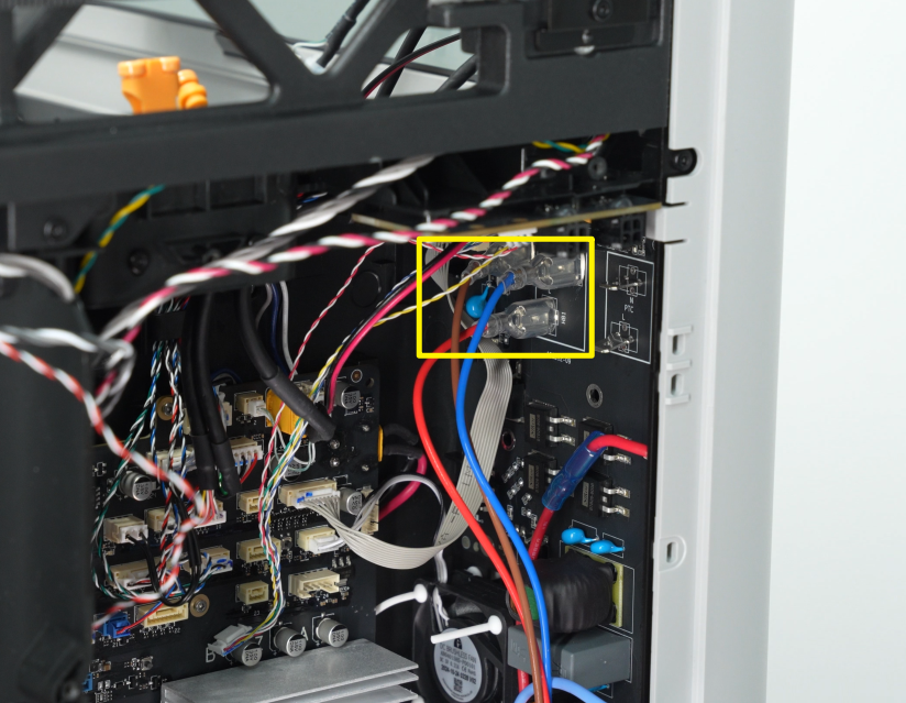
¶ Step 6 - Check the power cable connection under the heat bed
WARNING:
Always confirm that the power supply is disconnected before operation.
Because the connector is usually glued with white silicone gel, it may not be directly clear whether the connection is normal. Just use the tip of the tweezers to push the connector several times. After the pressing, connect the power to start the printer and set the bed temperature to confirm whether the problem is solved. If the problem is not resolved, continue to the next step to check the AC board.
 |
 |
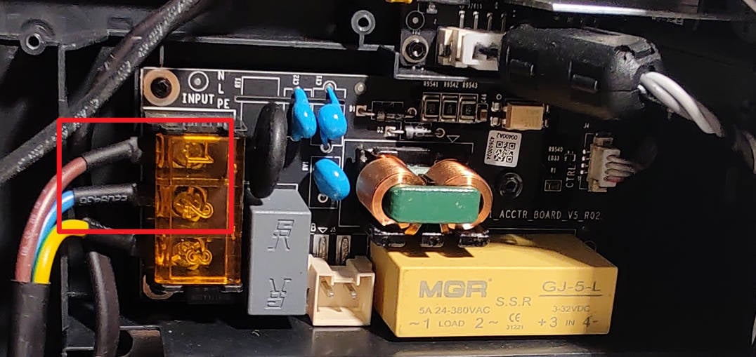
¶ Step 7 - Check the appearance of the AC power board
Visually check the appearance of the AC board, including shaking the input cables to check whether they are loose (if loose, reconnect and fix them) and whether the components on the board have obvious burn marks (if there are, please refer to this wiki to replace the AC power board ). Confirm that there is no abnormality, then proceed to the next step to confirm.
 )
)
¶ Step 8 - Check AC board voltage output
WARNING:
⚡Shock Hazard⚡ - can cause serious injury or death. This operation detects the mains voltage, and it is not recommended for personnel without relevant knowledge to operate. Skip this step if you don't know what you're doing.
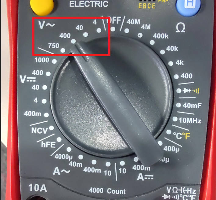
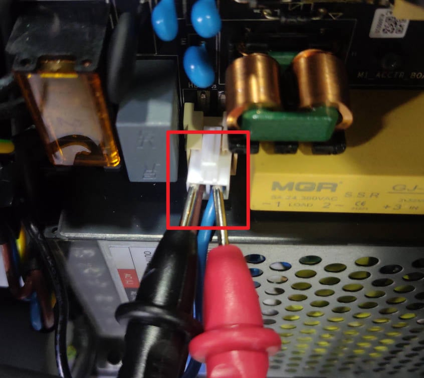
When the printer is turned on, and the heatbed is heating, use the AC voltage test file of the multimeter to check the output voltage, which should be the same as the local voltage. If the output voltage is abnormal, the AC board is faulty. Please refer to this wiki to replace the AC power board.
 |
 |
If the above operation fails to eliminate the fault, you need to contact the service team for confirmation.
¶ Assembly
After troubleshooting, the dismantled parts need to be reassembled. The steps are as follows:
¶ Step 1 - Install the power module protective cover
Install the power module protective cover, and secure it with the 6 screws.
¶ Step 2 - Install the excess chute
Install the excess chute, pay attention to the buckles on both sides and use the 2 screws to secure it.
 |
|
¶ Step 3 - Install the rear cover
Pass the PTFE tube through the tube bracket, first install the right-side belt tension port, then the left-side to install the rear cover.
|
 |
¶ Step 4 - Install the 10+4 screws
Install the 10 + 4 screws (see picture).
|
|
¶ H2 Series
You can adjust the order of steps as needed.
¶ Disassembly
¶ Step 1. Remove the printer's rear cover and AC board cover.
For detailed steps, please refer to Replace H2 Series AC Board/AC board Cover.
¶ Inspection
¶ Step 2. Check the AC board power connection.
Unplug the power cord, confirm the pins are working properly, and reconnect. Turn on the printer and set the heatbed temperature to see if the issue is resolved. If not, disconnect the power cord and proceed to the next step.
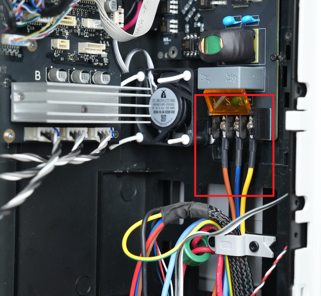
¶ Step 3. Check the heatbed resistance.
Disconnect the cables shown in the image below, and use a multimeter to measure the resistance between the cables.
Normal resistance values are shown in the table below.
| Resistance between blue and red wire | Resistance between blue and brown wire | |
|---|---|---|
| 220V high voltage version | 28~35 Ω | 180~220 Ω |
| 110V low voltage version | 9~11 Ω | 45~55 Ω |
If the resistance is zero or excessively high, the heatbed power connection may be open or the heatbed components may be burned out. Please refer to the wiki Replace H2S Heatbed Unit or Replace H2D Heatbed Unit to replace the heatbed.
¶ Step 4. Check the AC board.
Check the AC board, shake it to check if the power input cable is loose (if so, reconnect and secure it). Then, check for any visible signs of burnout on the components on the board (if so, refer to Replace H2 Series AC Board/AC board Cover to replace the AC board). If there are no abnormalities, please proceed to the next step.
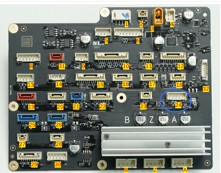
¶ Step 5. Check the heatbed temperature resistor.
Check that the heatbed temperature resistor connector (No. 24) on the MC board is fully inserted. If necessary, replug it.
If the above guides do not solve the problem, please contact our customer service team.
¶ Assembly
¶ Step 6. Install the AC board cover and printer rear panel.
Please refer to the Wiki Replacing the H2 Series AC Board/AC Board Cable Management Cover to reinstall the AC board cover and printer rear panel in sequence.
¶ Error Message
HMS_0300-0100-0001-0008: An abnormality occurs during the heating process of the heatbed. The heating modules may be broken.
"An abnormality occurs during the heating process of the heatbed. The heating modules may be broken."
0300-0100-0001-0008
¶ End Notes
We hope the detailed guide provided has been helpful and informative.
To ensure a safe and effective execution, if you have any concerns or questions about the process described in this article, we recommend submitting a Technical ticket regarding your issue. Please include a picture or video illustrating the problem, as well as any additional information related to your inquiry.