¶ Preface
During laser processing, smoke is generated. The laser air pump provides high-pressure airflow during laser operation to disperse the smoke and dust generated during cutting. This not only prevents the edges of the material from being charred and reduces the risk of fire but also protects the laser lens from smoke contamination. When used in conjunction with the automatic top vent, filter switch flap, chamber exhaust fan, active chamber exhaust, ventilation pipe adapter, and smoke ventilation pipe, the smoke and dust produced by laser cutting will be expelled from the printer's chamber exhaust fan outside the printer. For more installation guidelines on the smoke ventilation pipe, please refer to this relevant wiki. Laser Module Installation Guide
Although most of the smoke will be expelled through the smoke ventilation pipe, some smoke will still remain inside the printer. Therefore, the level of contamination inside the printer will be more severe compared to using only the 3D printing function if the laser module is used, requiring more frequent maintenance.
If the interior walls around the casing are not cleaned for an extended period, dirt can easily accumulate, and attachments on the front door and side panels may obstruct the view. Therefore, it is essential to regularly wipe these areas with alcohol and non-woven cloth. Additionally, the part cooling fan duct on the tool head, flow blocker, and magnet bracket should be cleaned regularly. Furthermore, the X-axis assembly, Y-axis and Z-axis linear rods and leadscrews should also be cleaned periodically with alcohol and non-woven cloth. It is important to note that after using alcohol to wipe down metal bearing parts, it is recommended to supplement with lubricating oil (for linear rods and rods) or grease (for lead screws).
To ensure the proper functioning of various intelligent visual detection and sensor detection, it is crucial to regularly clean the surfaces of all types of camera lenses and flame sensors. It is recommended to use alcohol and non-woven cloth to wipe the lenses. Additionally, clean the laser wrench marks, hotend marks, build plate and laser platform marks, and the parallelogram limit blocks inside the heatbed to prevent image blurring or misidentification of marks. When cleaning the cameras, please note that only use a small amount of alcohol and slightly squeeze the non-woven cloth dry before wiping to prevent alcohol from seeping into the plastic housing. For more information about intelligent detection functions, please refer to the relevant wiki. Introduction to H2D Intelligent Detection
Furthermore, components related to the exchange of air between the casing and the external environment are prone to accumulating dust. It is recommended to regularly use a brush to clean the accumulated dust. For the activated carbon air filter cover and the chamber exhaust at the back, they can also be removed for cleaning to ensure the proper operation of the equipment and extend its lifespan.
¶ Related Video
A real case of H2D laser operations and cleaning tips

¶ Maintenance frequency
H2D can assess the pollution level of the printer based on task type and duration, providing corresponding cleaning maintenance reminders (this feature requires upgrading the firmware to version 01.01.00.00 or newer). After receiving the printer, please upgrade the firmware to enable the cleaning reminder feature.
Please make sure to maintain the printer components and laser module as required to prevent potential security risks!
If only the 3D printing function is used, the recommended maintenance frequencies for each component are as follows:
| component | cleaning and maintenance frequency | Precautions | component | cleaning and maintenance frequency | Precautions |
|---|---|---|---|---|---|
| Printer exterior and screen | 3 months | X-axis assembly | 1 months | Apply lubricating oil after cleaning | |
| Heatbed | 3 months | Y-axis linear rods | 3 months | Apply lubricating oil after cleaning | |
| Toolhead | 3 months | Z-axis linear rods and leadscrews | 3 months | Apply lubricating grease after cleaning | |
| Nozzle camera | 3 months | Apply a small amount of alcohol to the non-woven cloth and squeeze it dry | Toolhead camera | 3 months | Apply a small amount of alcohol to the non-woven cloth and squeeze it dry |
| Birdseye Camera | 3 months | Apply a small amount of alcohol to the non-woven cloth and squeeze it dry | Live camera | 3 months | Apply a small amount of alcohol to the non-woven cloth and squeeze it dry |
| Flame sensor | 3 months | Apply a small amount of alcohol to the non-woven cloth and squeeze it dry | Enclosure top fame | 3 months | |
| Auxiliary part cooling fan | 3 months | Left/Right side panel | 3 months | ||
| Left/Right inner lining | 3 months | Activated carbon air filter cover | 3 months | ||
| Chamber exhaust fan | 3 months | Chamber exhaust | 3 months | ||
| Left nozzle lift linear rail | 1 months | Apply lubricating oil after cleaning |
Note: If printing with high-temperature/engineering filament continuously over a long period, it is recommended to increase the maintenance frequency to once a month.
¶ Maintenance steps
Before commencing the cleaning and maintenance procedures, please ensure that the printer is turned off.
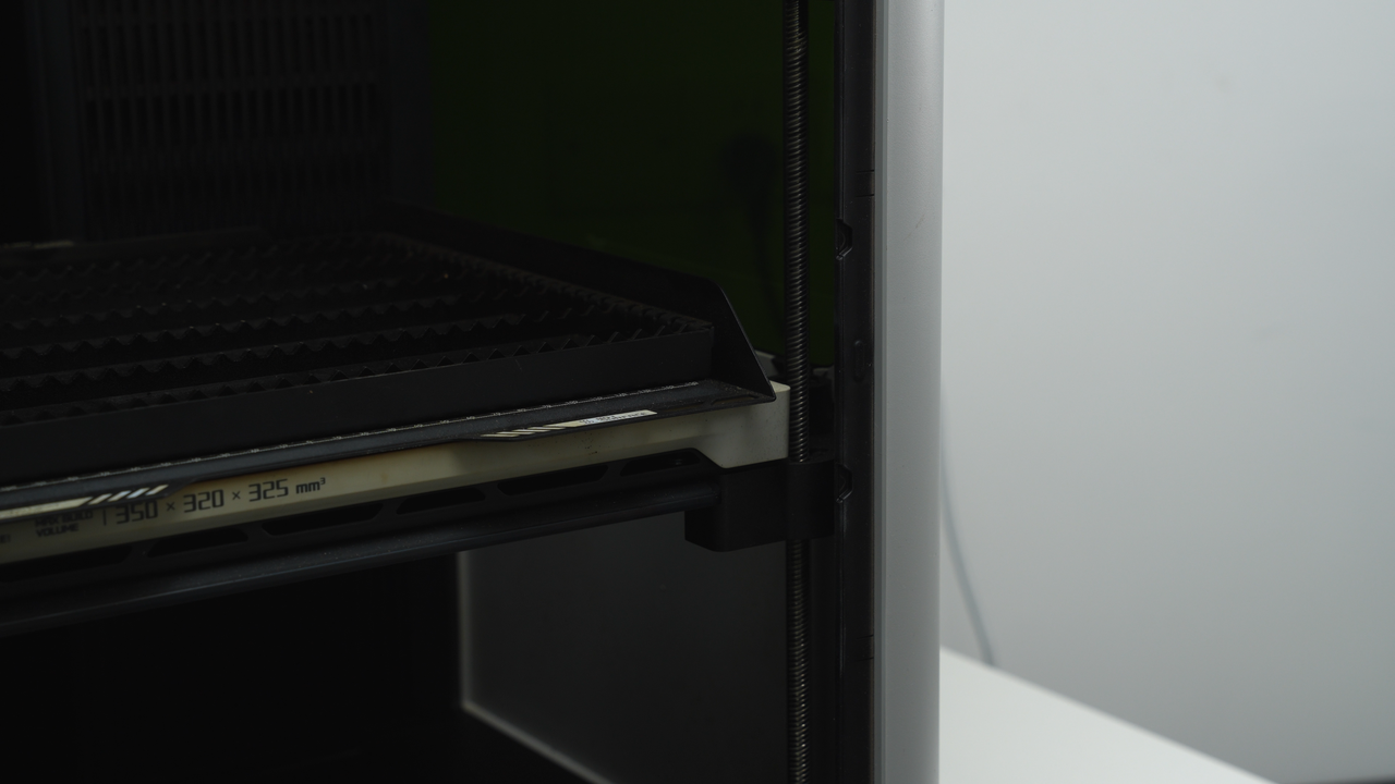
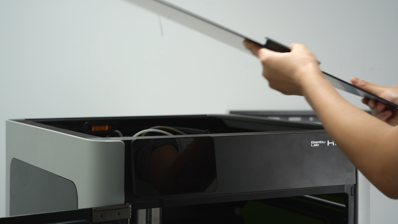
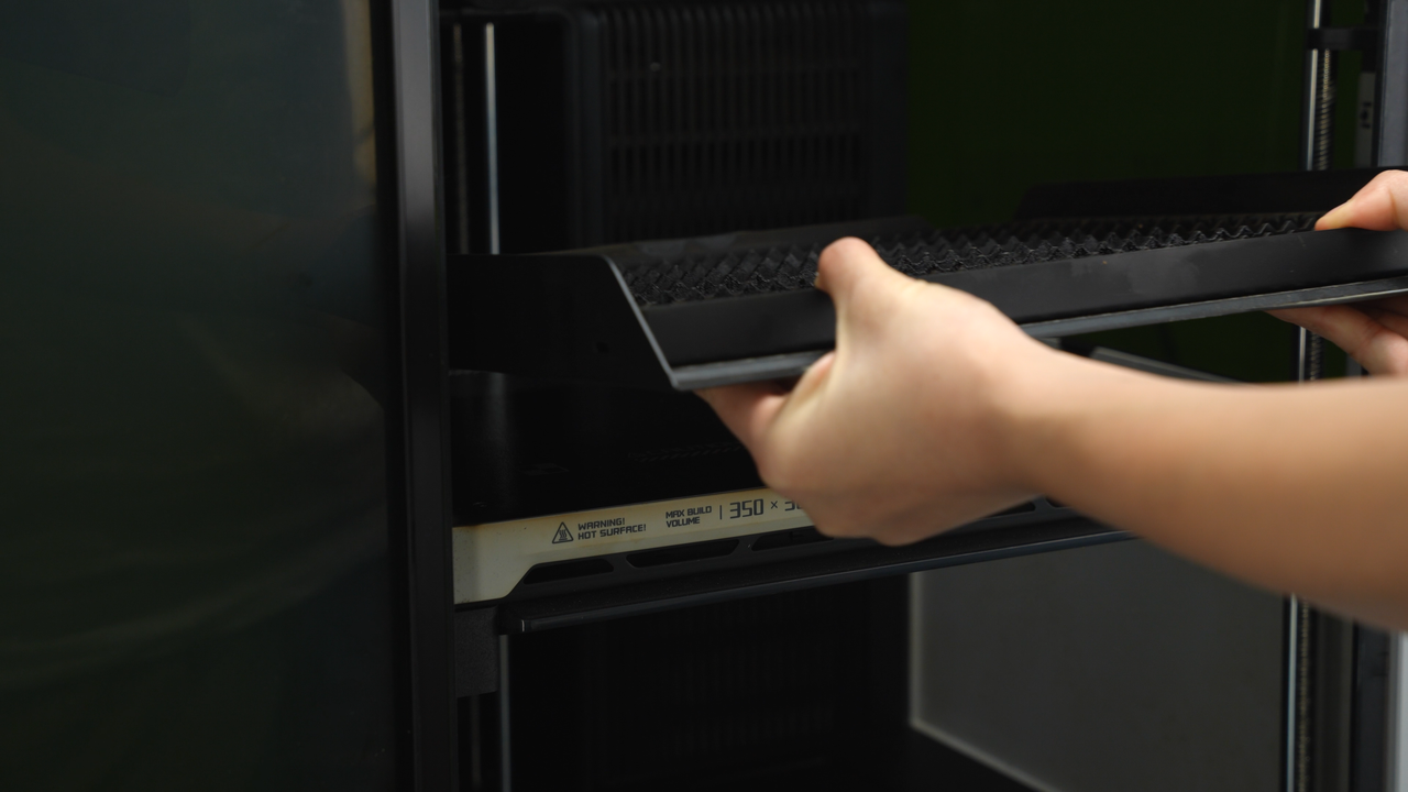
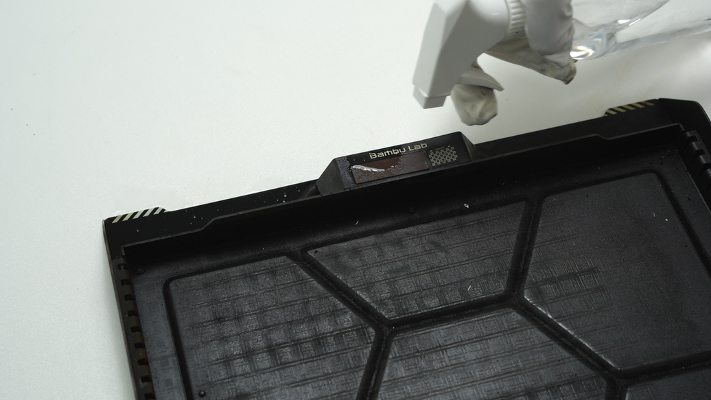
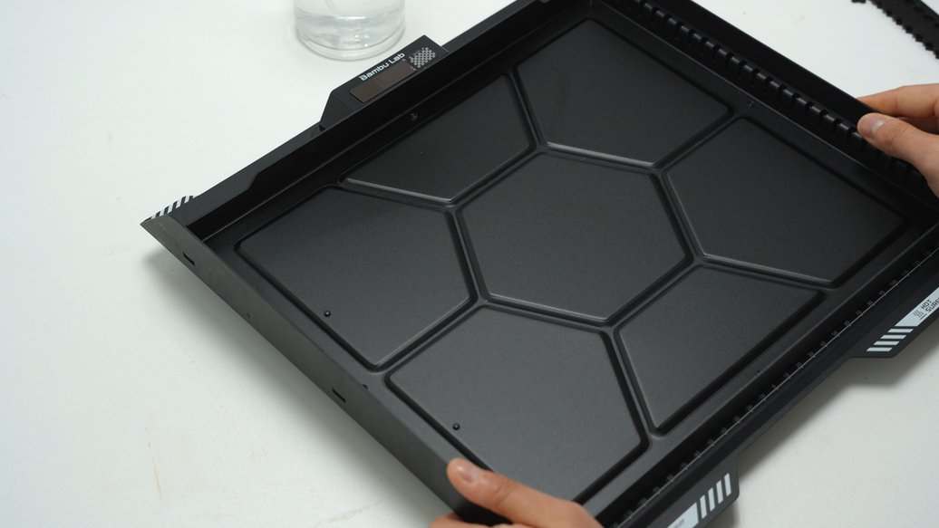
¶ Step1. Remove the laser platform
Open the front door of the printer and remove the top cover, then take off the laser platform from the heated.
 |
 |
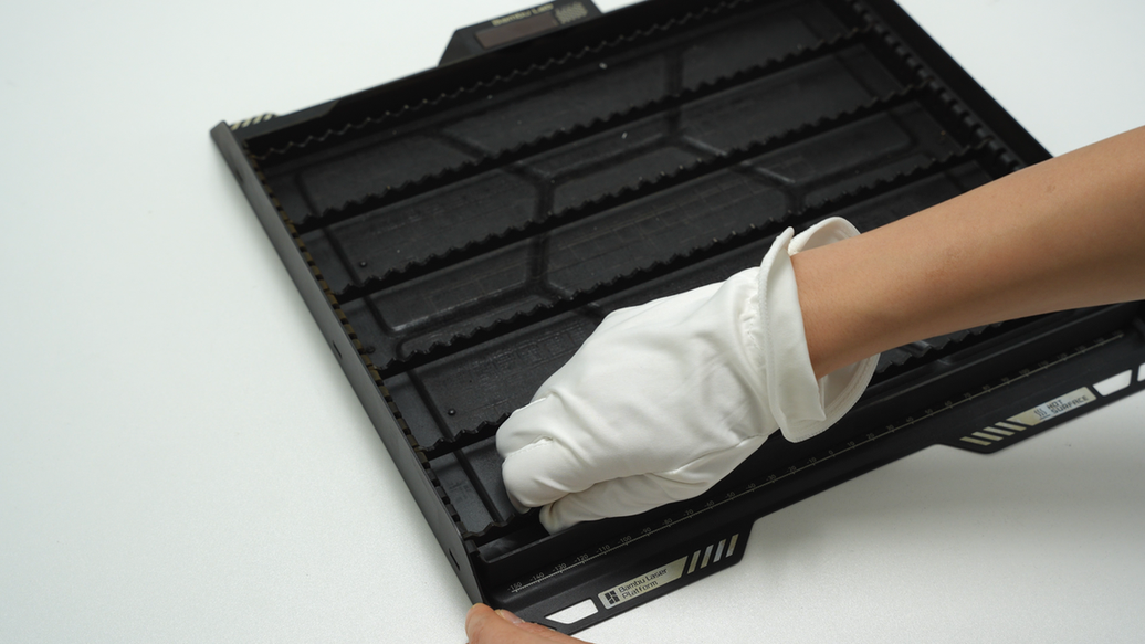
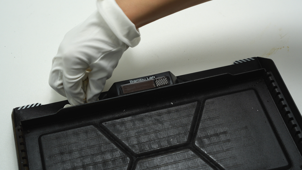
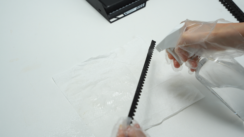
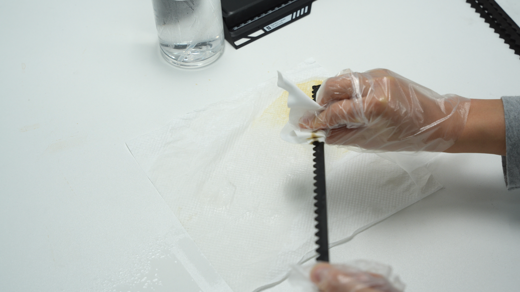
¶ Step2. Clean the laser platform and slats
Wear gloves and remove all slats from the laser platform.
 |
 |
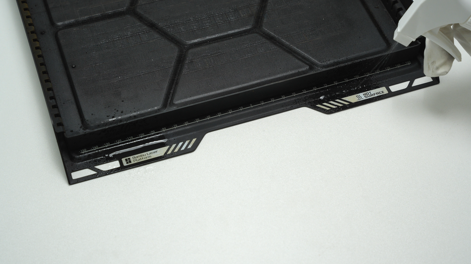
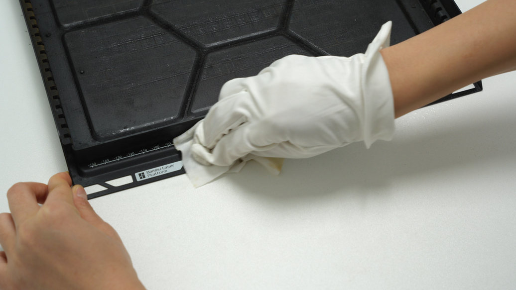
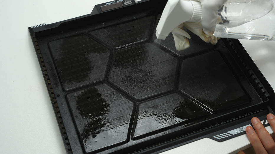
First, spray alcohol on the marks around the laser platform and carefully wipe them off with a non-woven cloth to clean the stains.
 |
 |
 |
 |
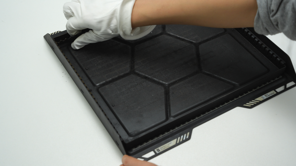
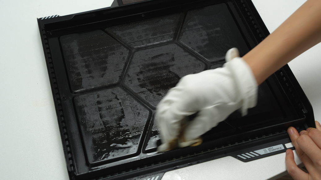
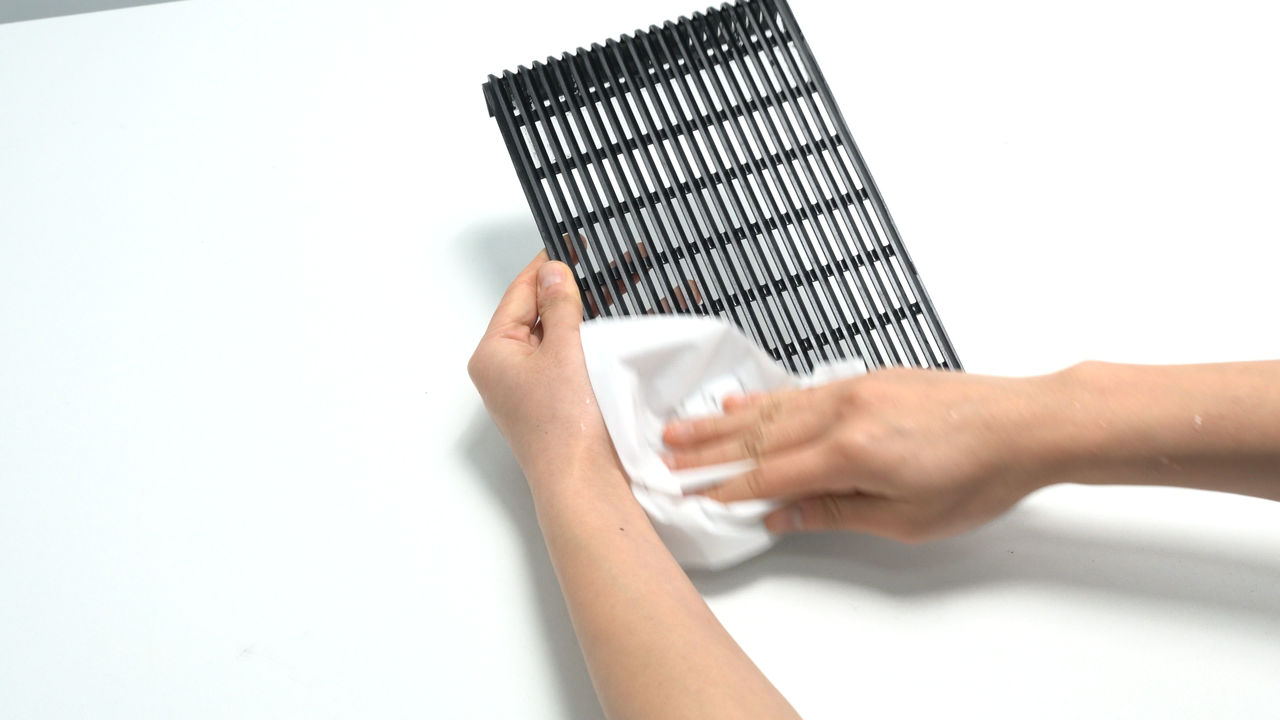
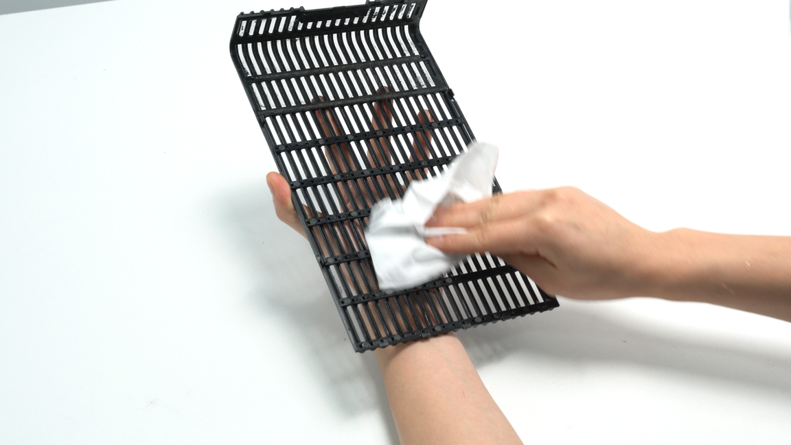
Next, spray alcohol inside the laser platform and carefully wipe it with the non-woven cloth.
 |
 |
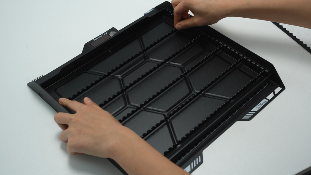
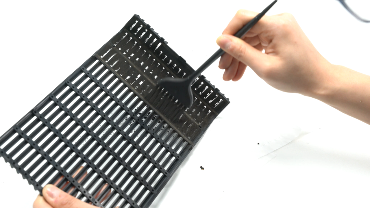
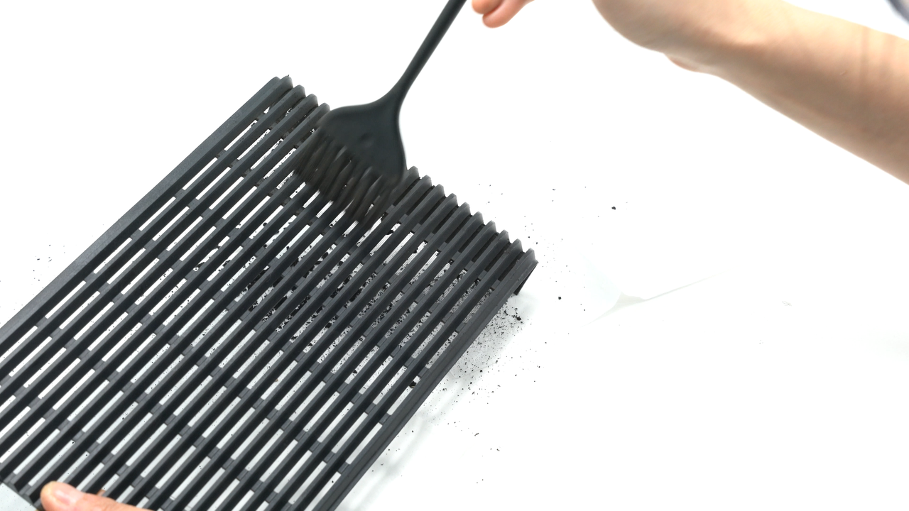
Spray alcohol on the slats, similarly wipe them with a non-woven cloth to clean the stains. Once cleaning is done, reinstall the slats back into the slots on the laser platform.
 |
 |
¶ Step3. Remove the laser module
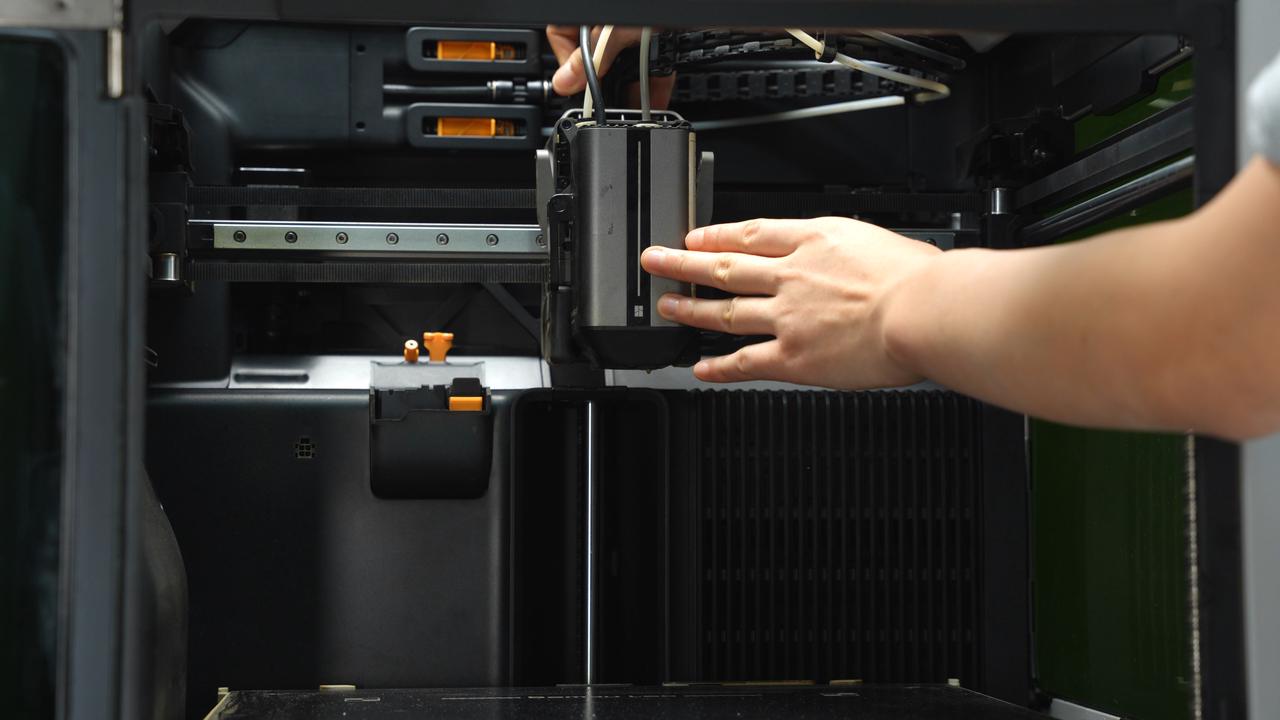
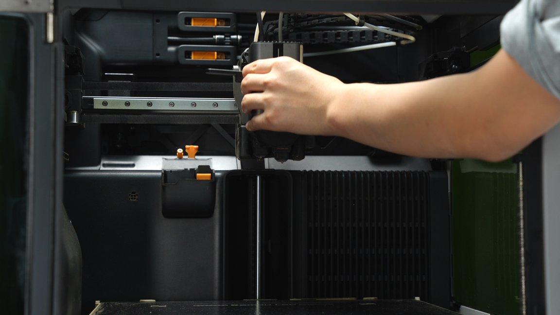
Disconnect the laser connector, unlock the quick-release lever, and remove the laser module.
 |
 |
For laser module cleaning, please refer to: Regular maintenance recommendations for laser module.
¶ Step4. Clean the front door and screen
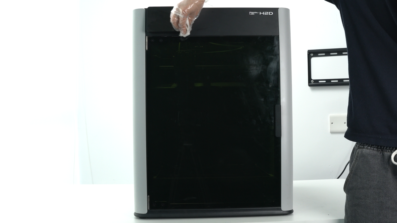
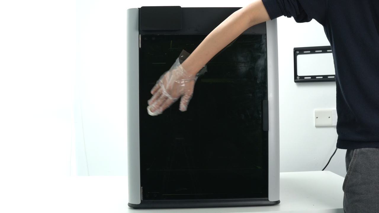
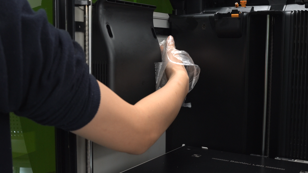
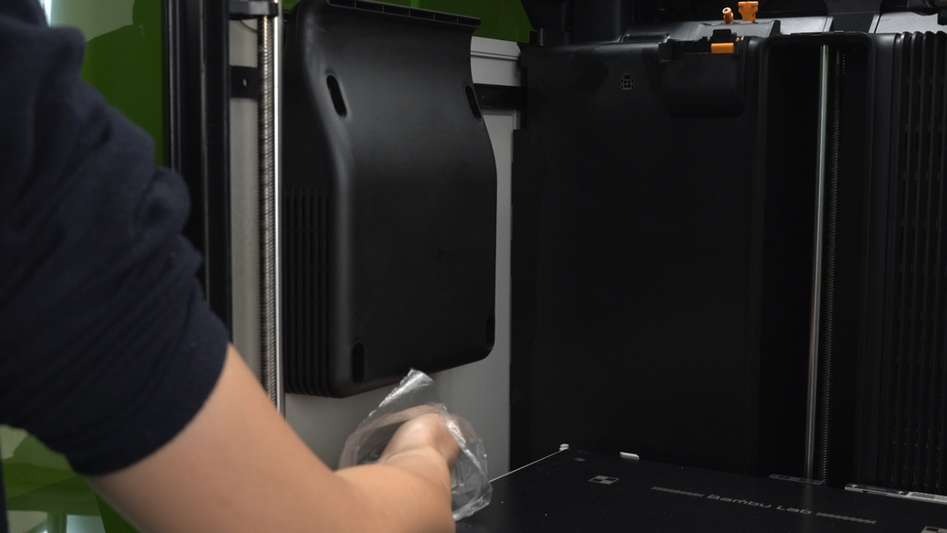
Use a non-woven cloth sprayed with alcohol to wipe the printer screen and the outer surface of the front door, cleaning off the dust.
 |
 |
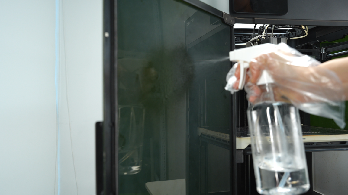
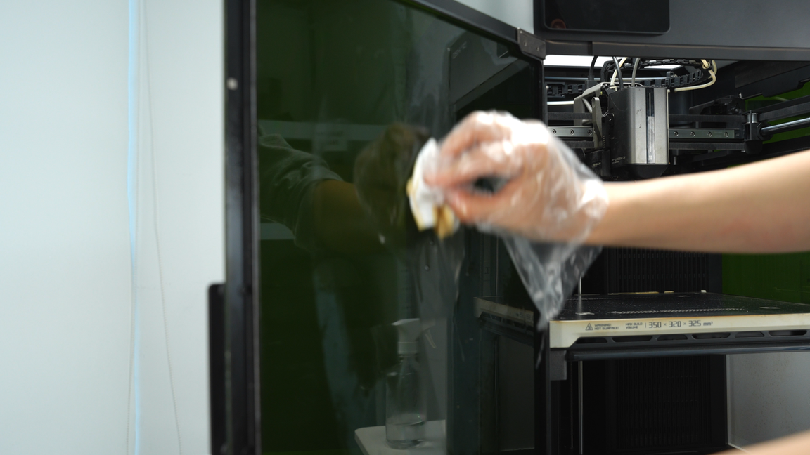
Next, spray alcohol on the inside of the front door and wipe it with non-woven cloth.
 |
 |
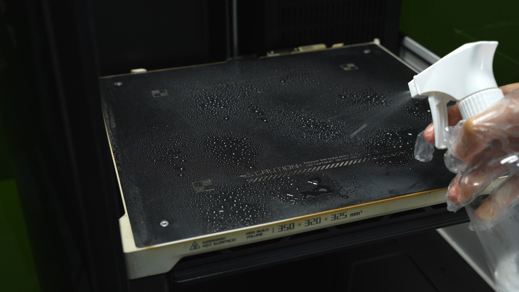
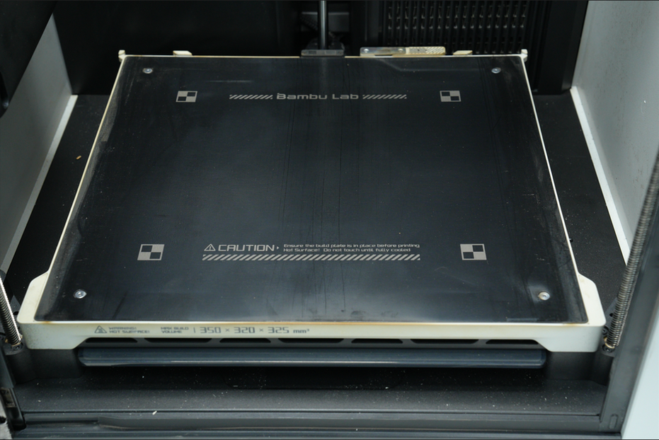
¶ Step5. Clean the heatbed
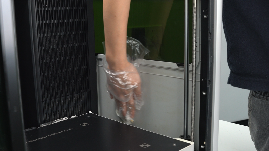
Spray alcohol on the heatbed and wipe the surface with a non-woven cloth.
 |
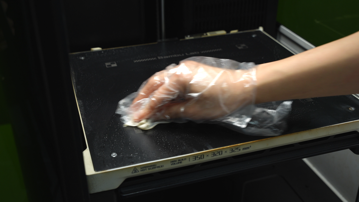 |
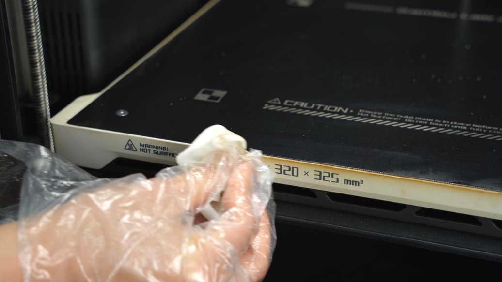
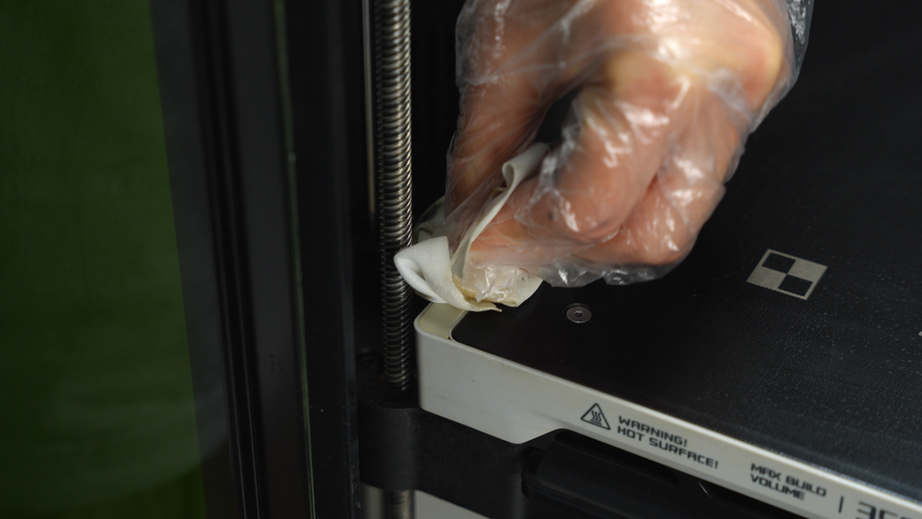
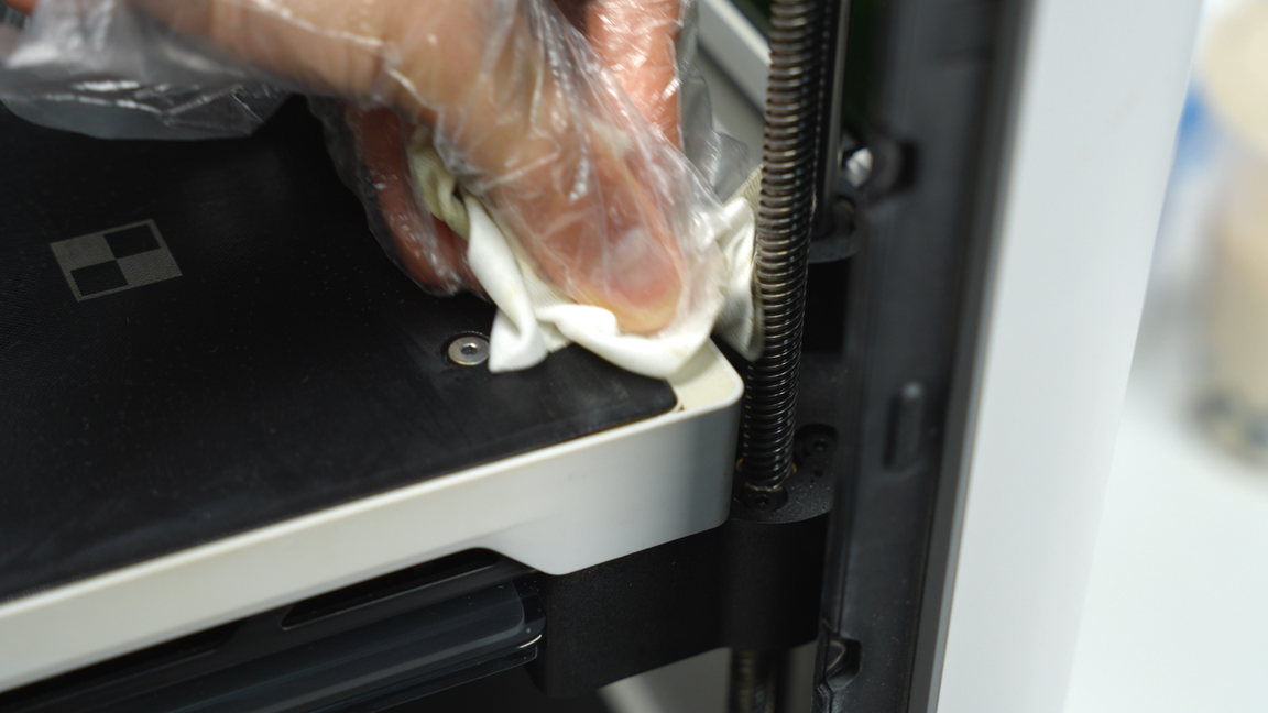
After wiping the heatbed surface clean, continue to wipe around the edges of the heatbed to remove any stains.
 |
 |
 |
 |
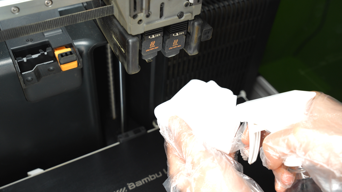
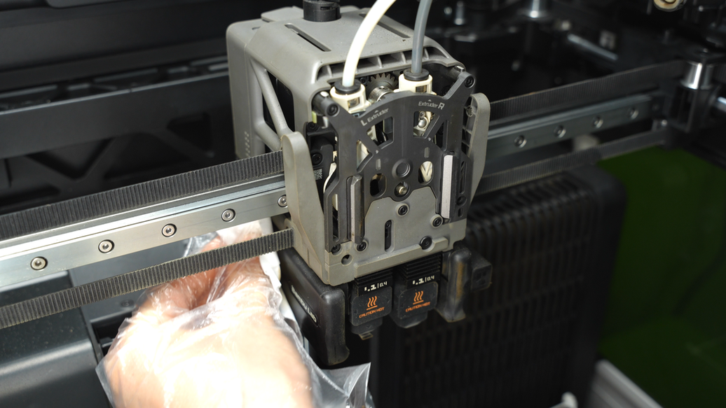
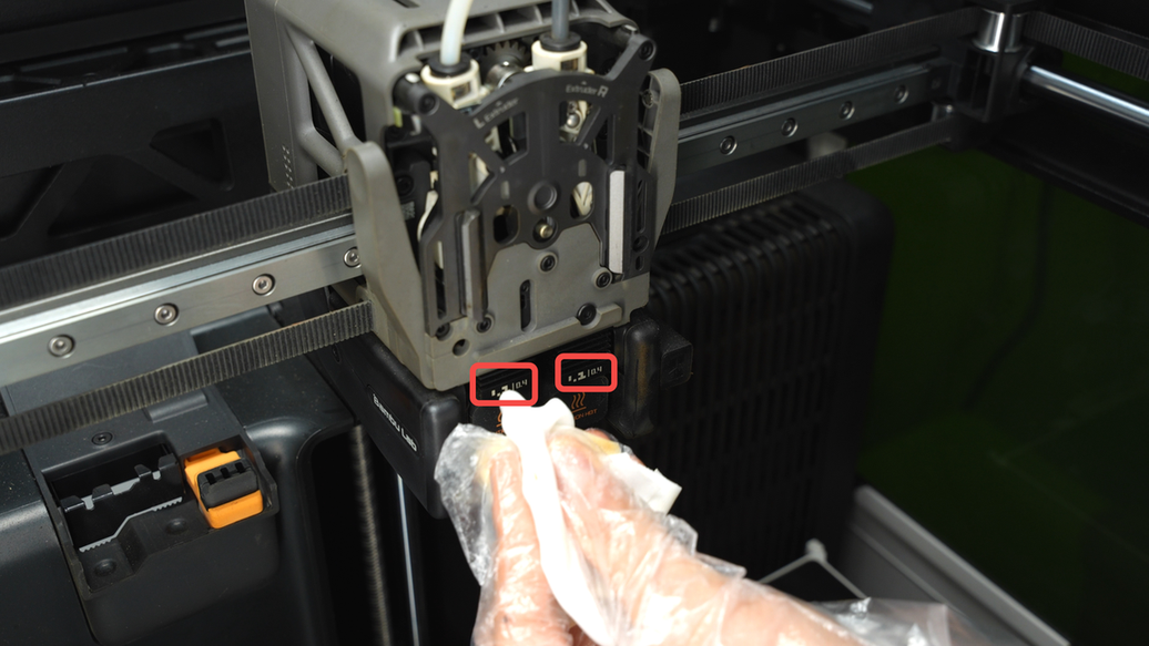
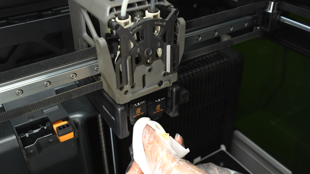
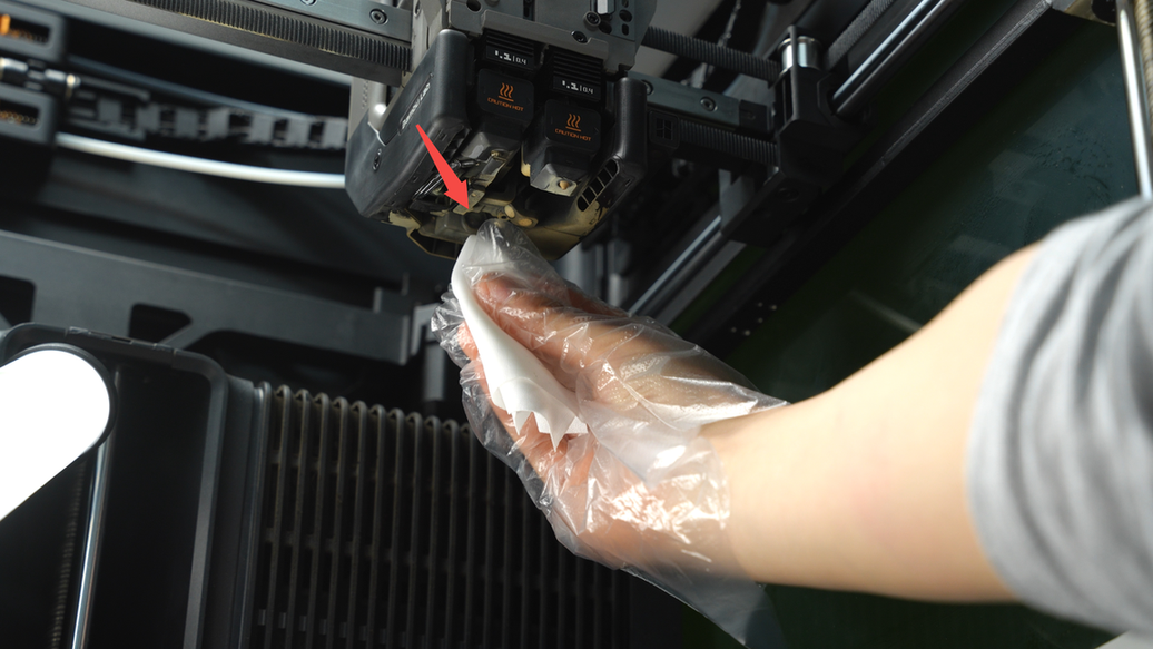
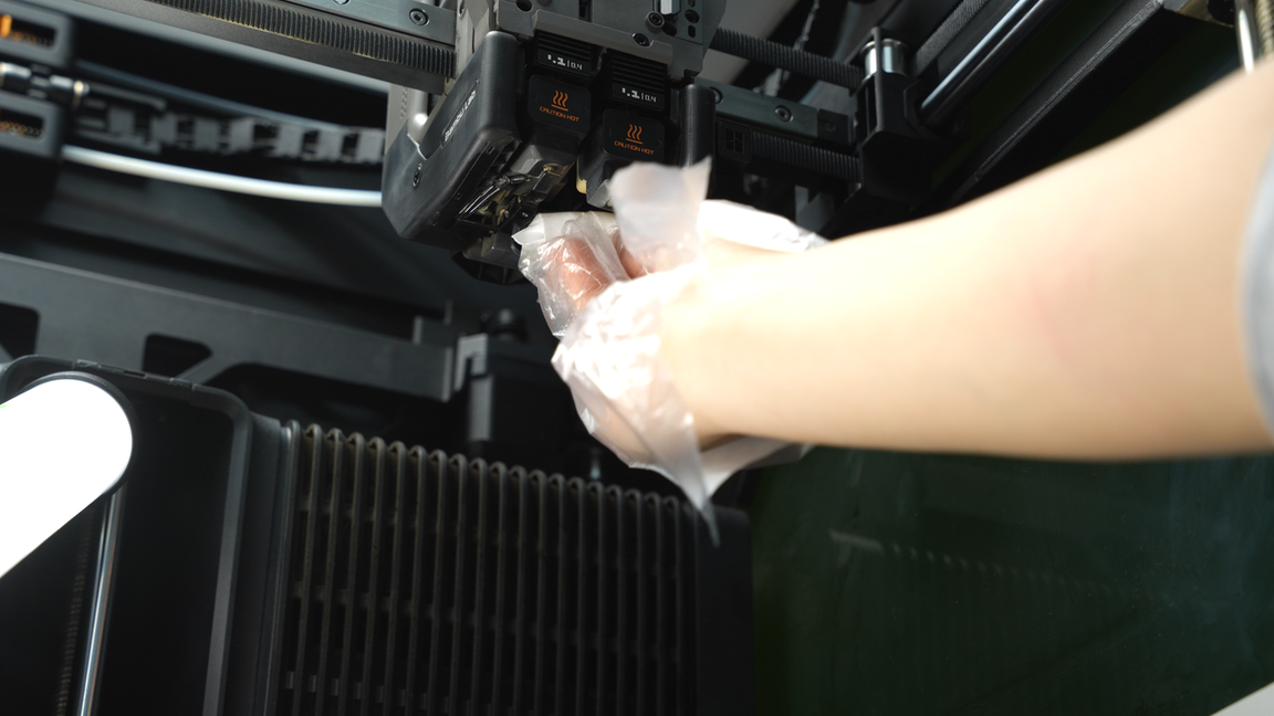
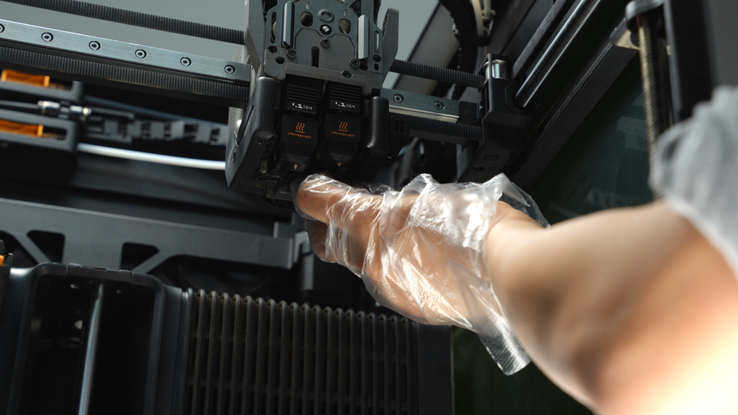
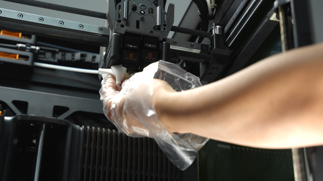
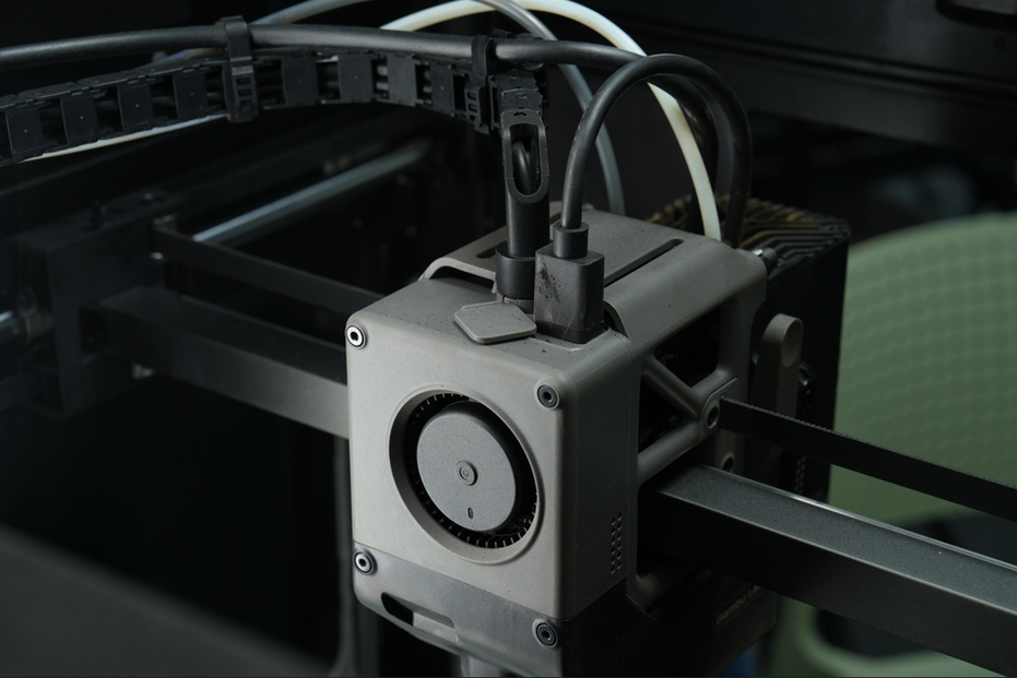
¶ Step6. Clean the toolhead
After cleaning the heatbed, you can add some alcohol to keep the non-woven cloth moist, ensuring a good cleaning effect. Start cleaning from the part cooling fan duct and then focus on cleaning the markers on both hotends to ensure they are clearly visible. Also, wipe the silicone socks of the hotends.
 |
 |
 |
 |
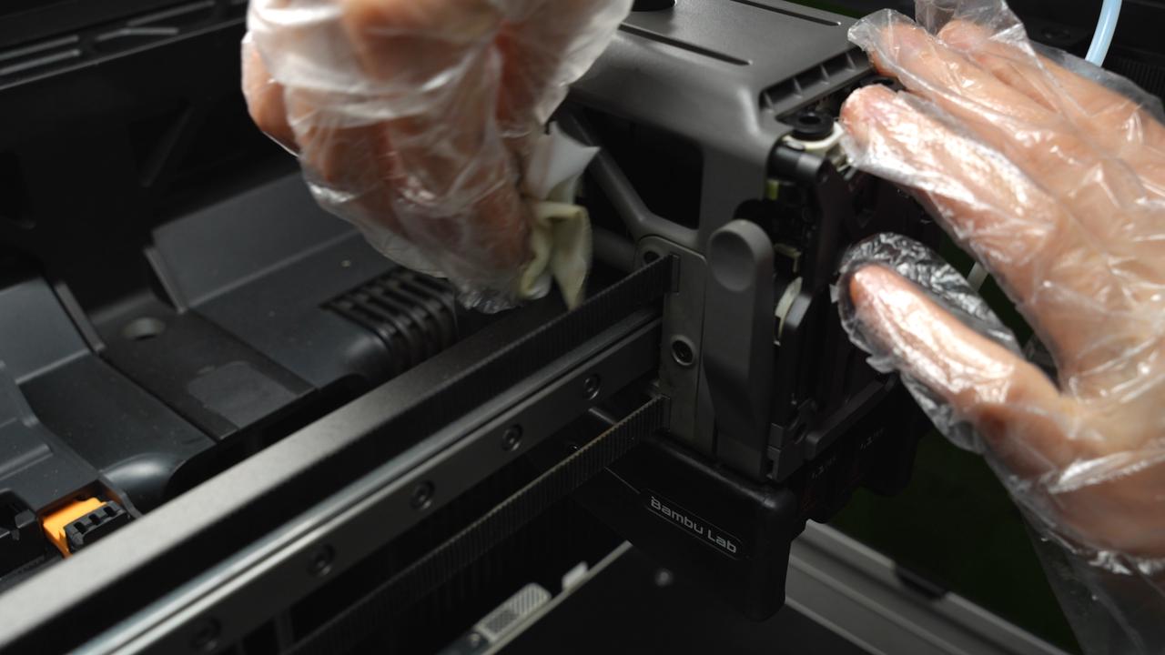
Next, wipe the extruder front cover, extruder filament guide, left and right cutters, and the top of the extruder to ensure that the dust is thoroughly cleaned.
 |
 |
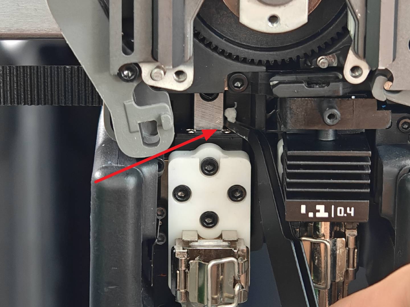
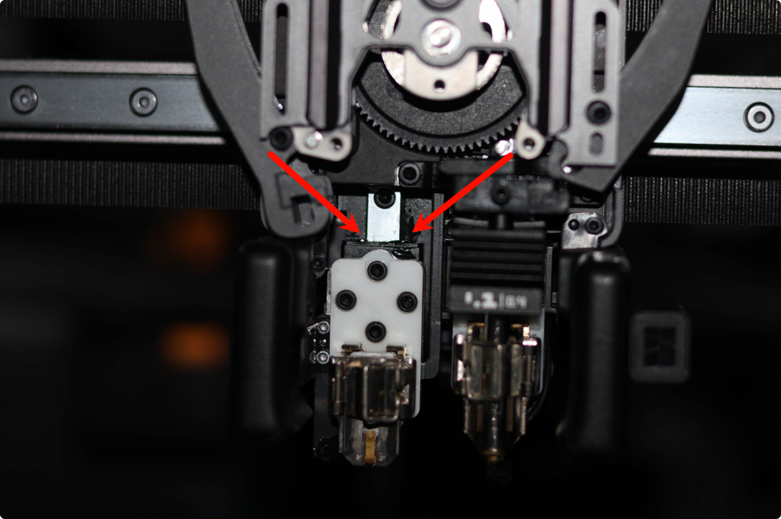
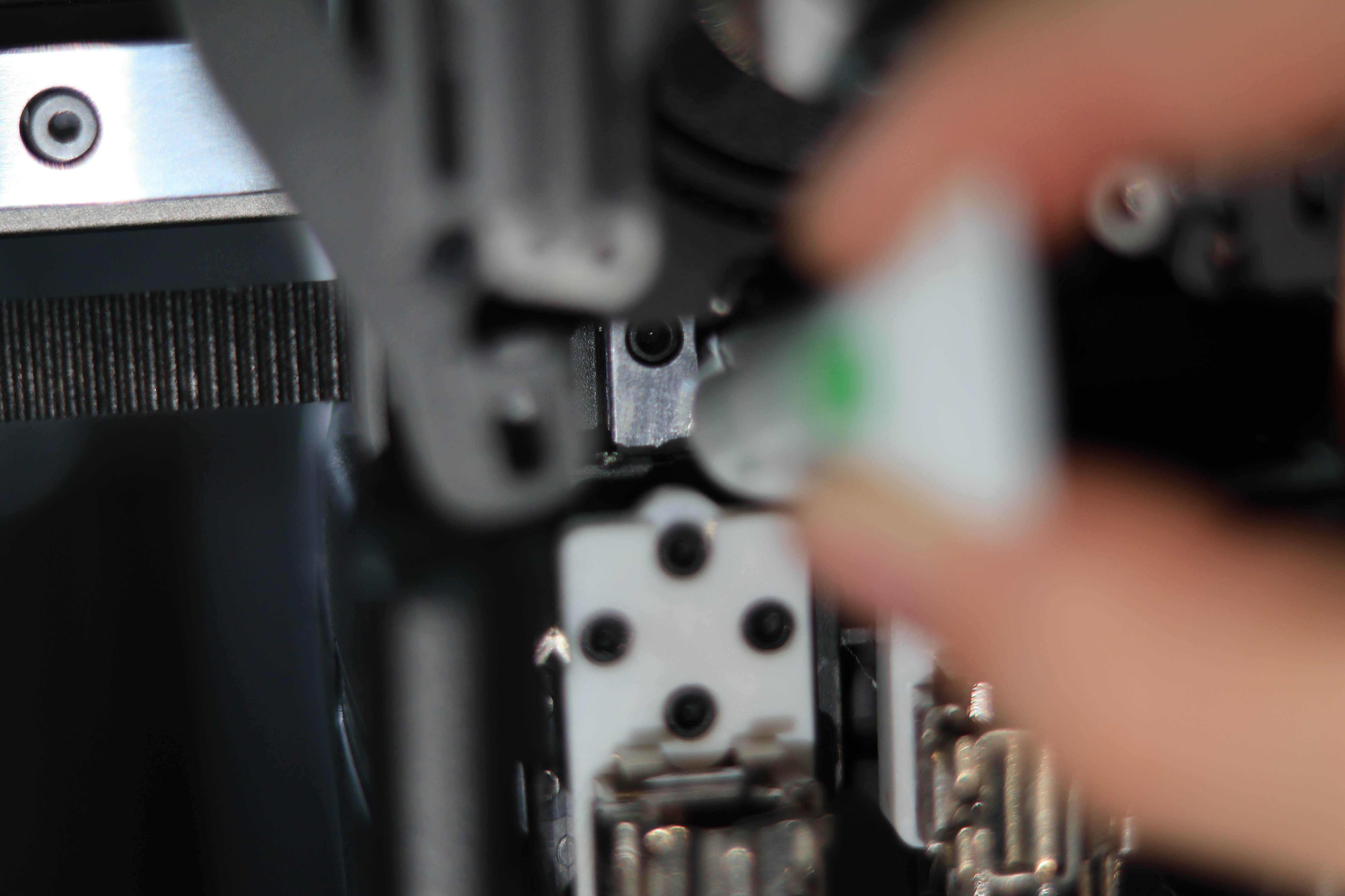
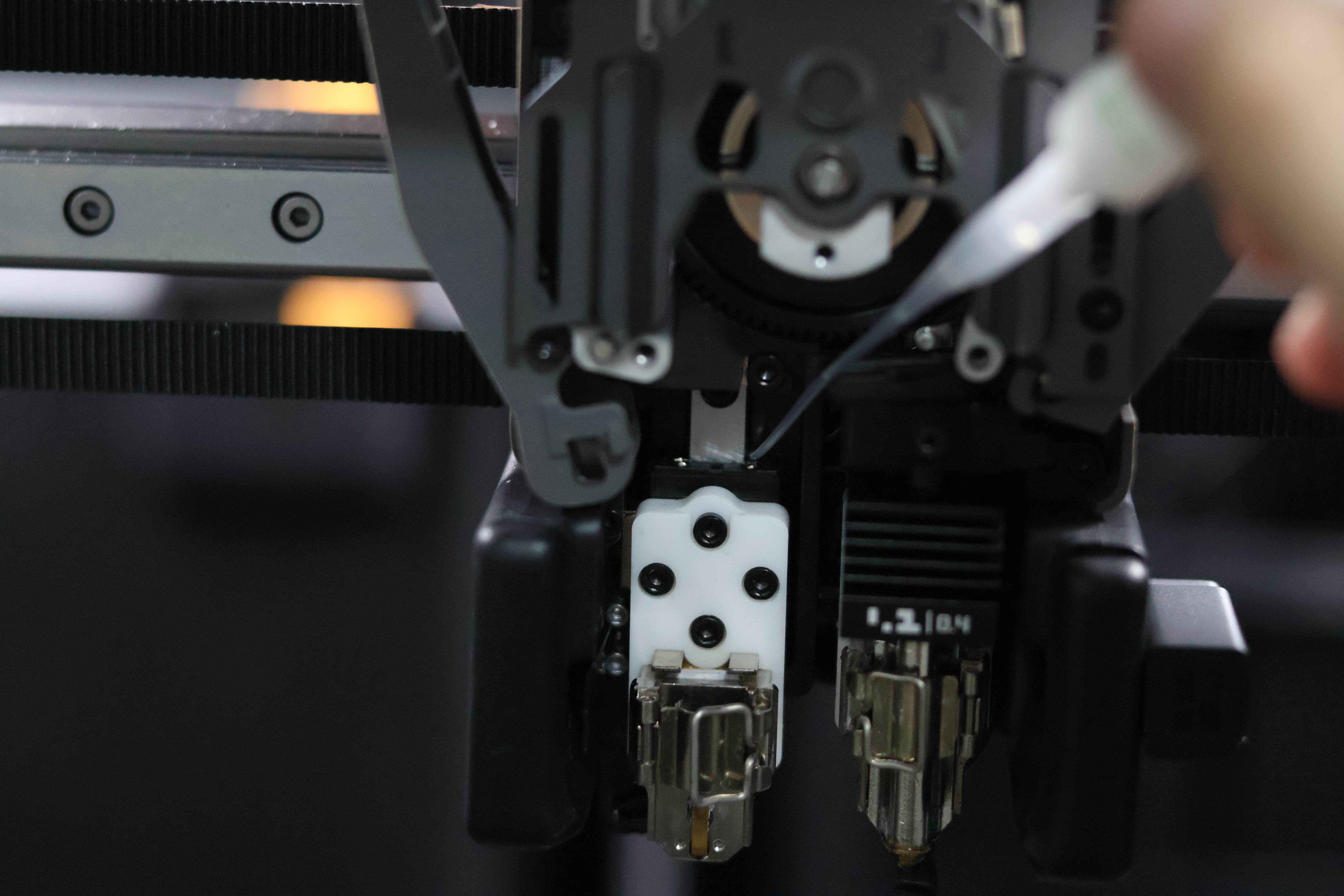
Clean and lubricate the lifting rail of the left nozzle assembly. Remove the front nozzle assembly and the Dual extruder filament guide; during the process, use tweezers to clear any debris, and then apply lubricant to both sides of the rail.
 |
 |
 |
 |
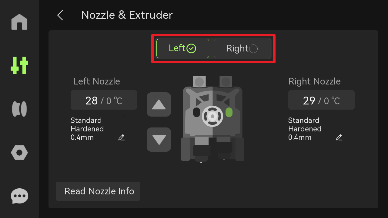
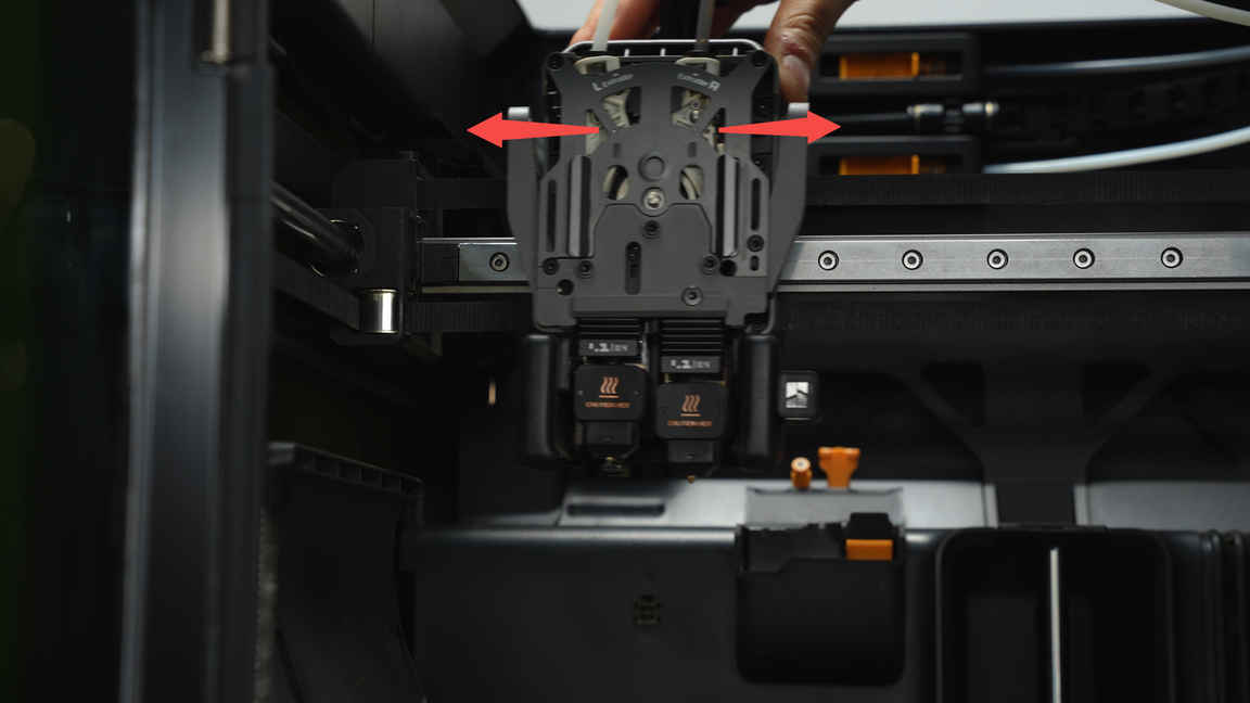
After completing the maintenance of the nozzle lifting rail, it is necessary to operate the switching of the left and right nozzles on the screen 3-5 times to allow the oil to fully infiltrate and spread.
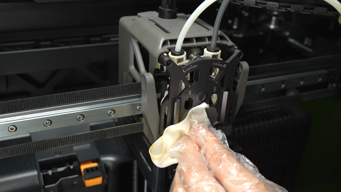
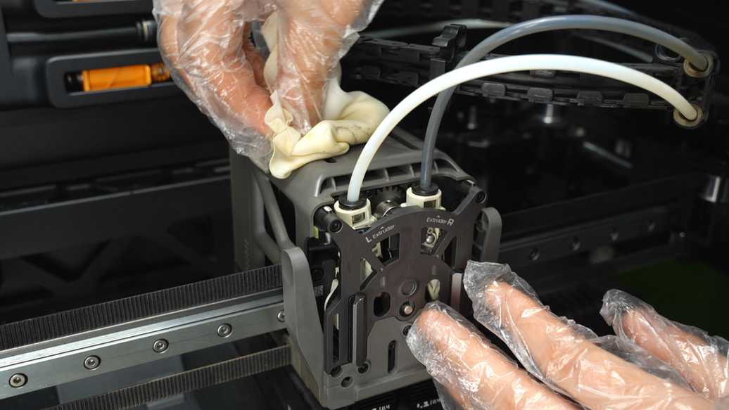
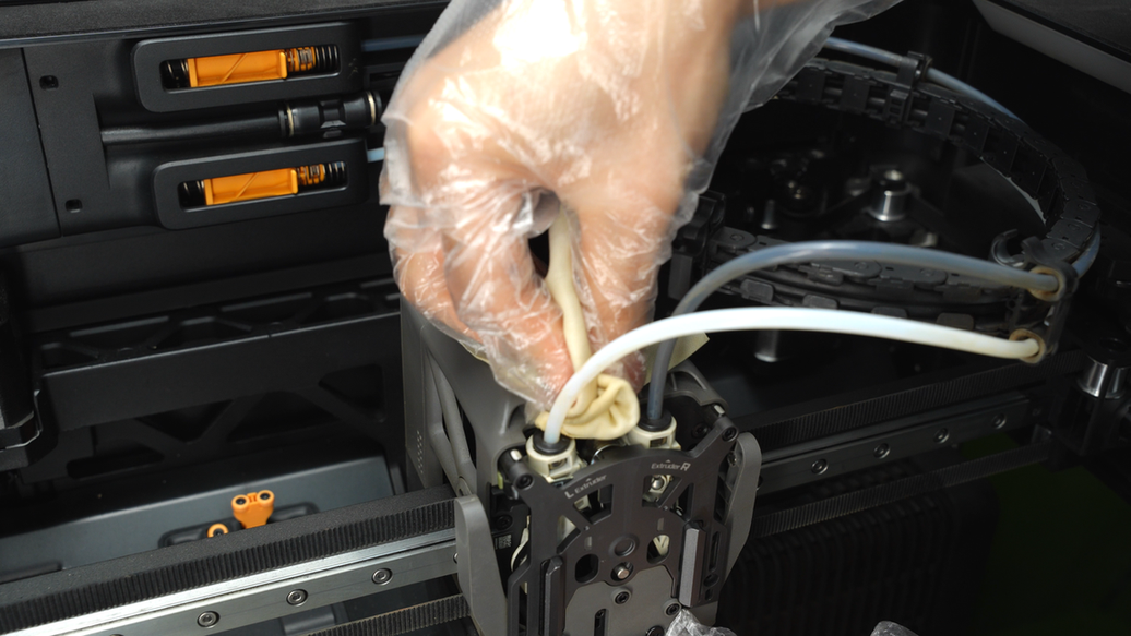
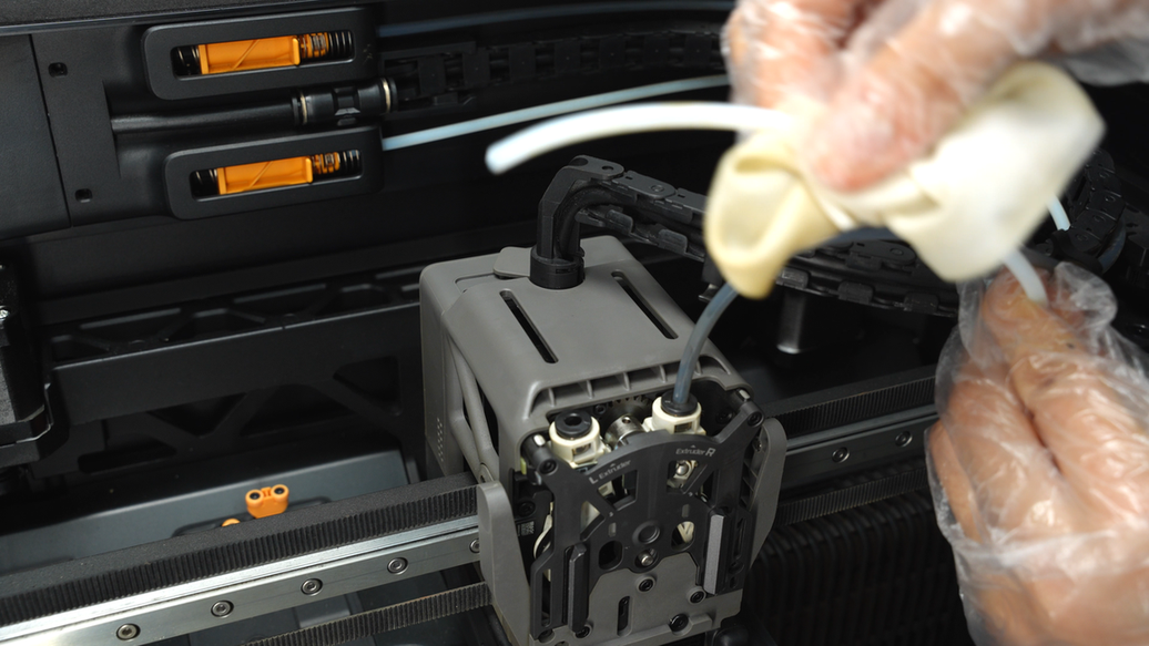
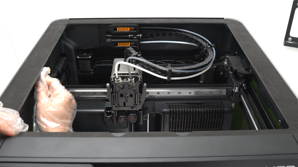
Clean the top of the extruder idlers, remove the PTFE tube and wipe it, then clean the pneumatic connectors. Repeat the same cleaning process for the other PTFE tube as well.
 |
 |
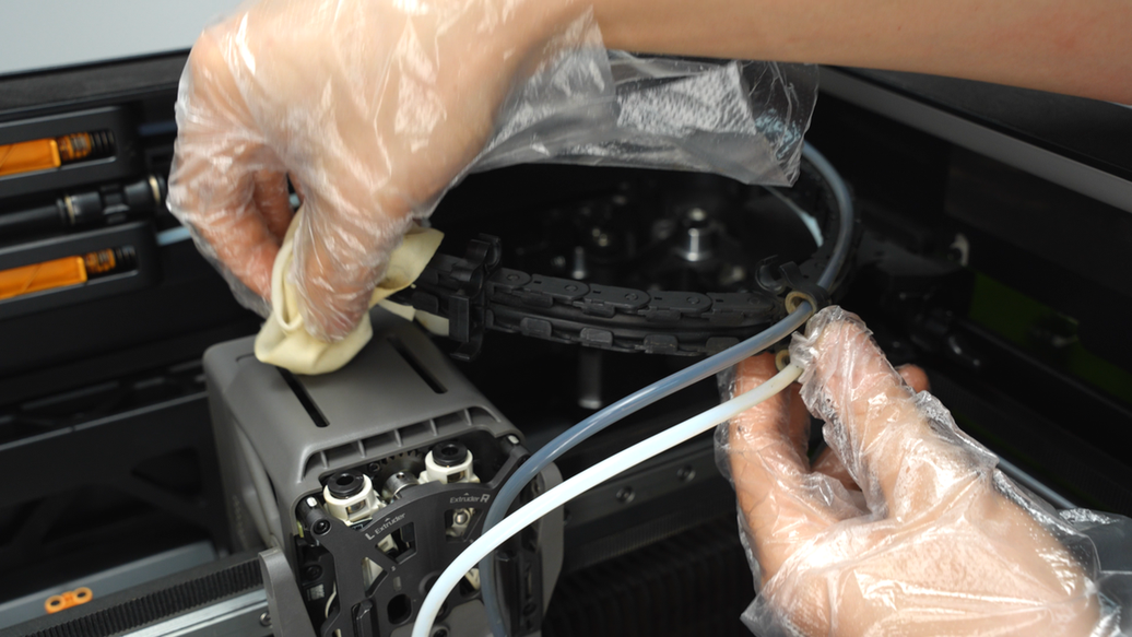
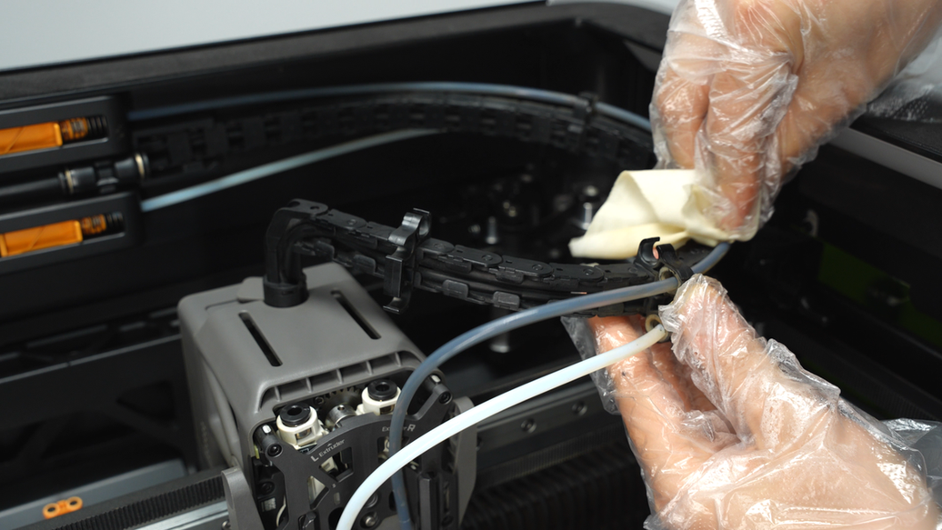
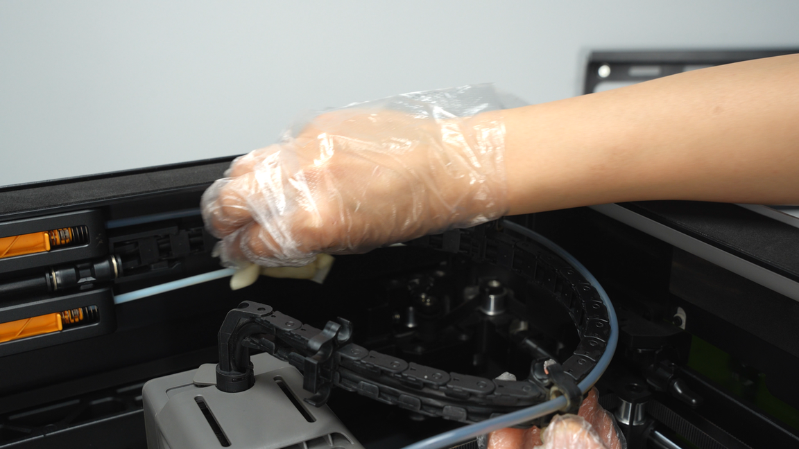
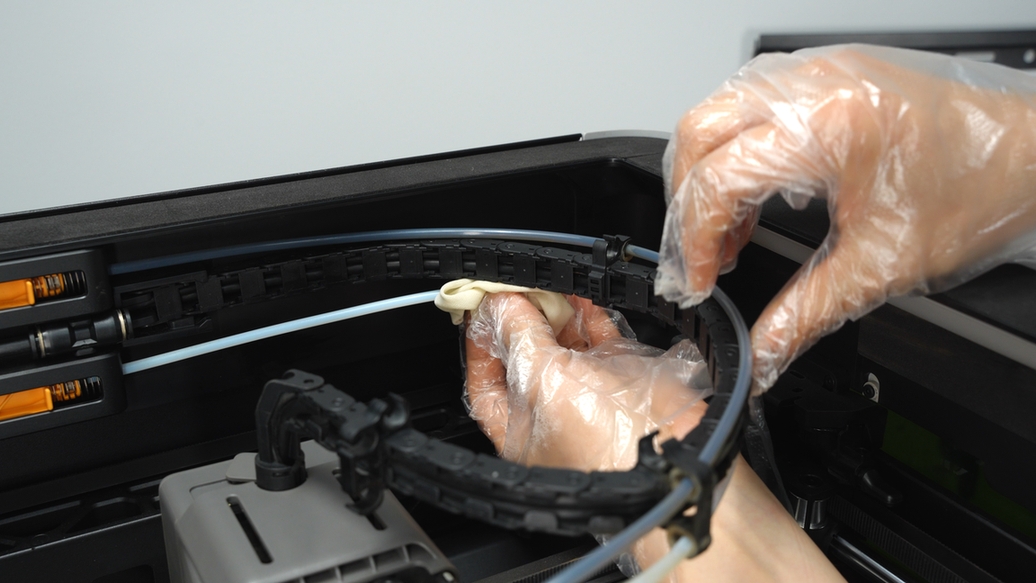
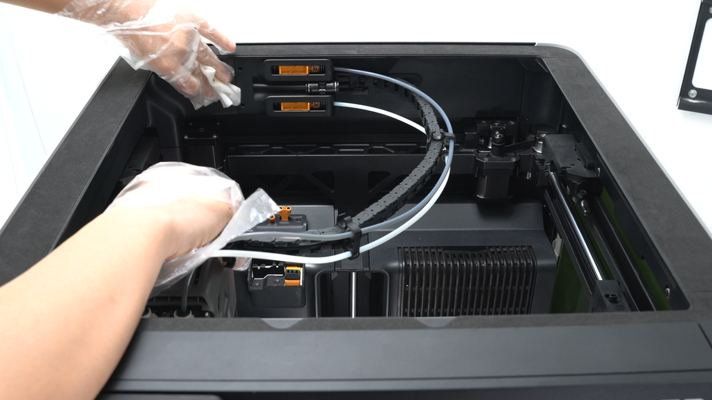
After cleaning the pneumatic connectors and PTFE tubes, do not reinstall the PTFE tubes yet. Further wipe the cable chain and the sections of PTFE tubes on the chain.
 |
 |
 |
 |
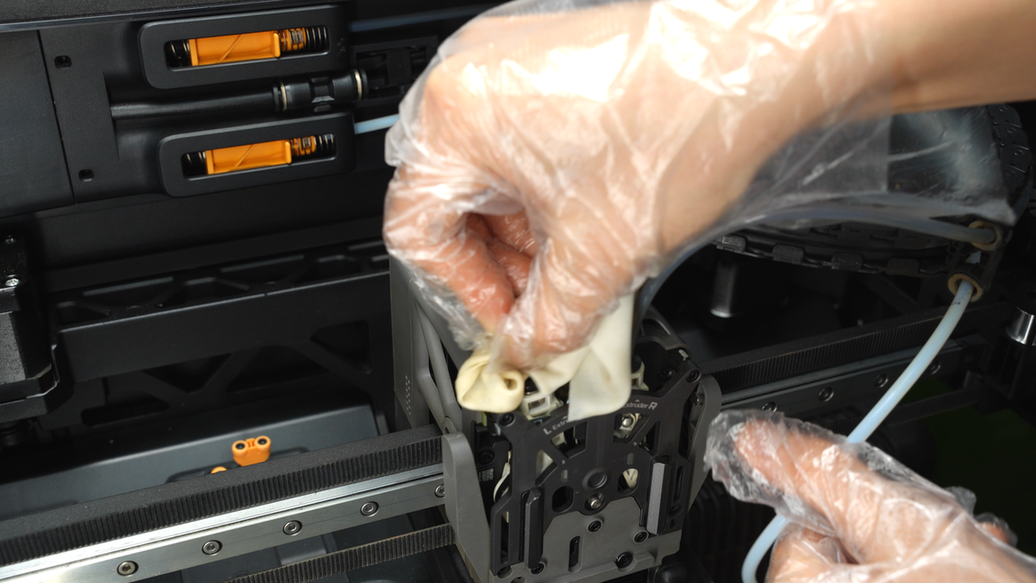
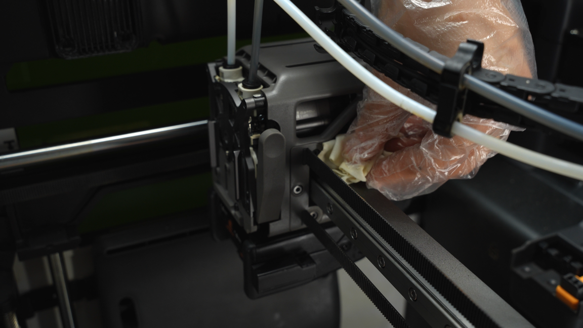
Finally, clean the frames on the left and right sides of the tool head.
 |
 |
¶ Step7. Clean and lubricate the X-axis assembly
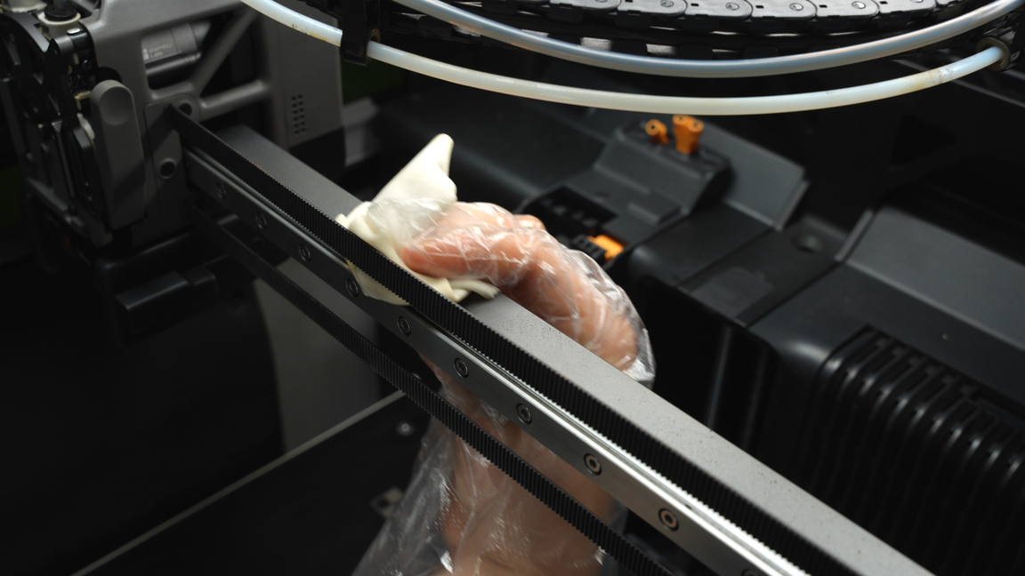
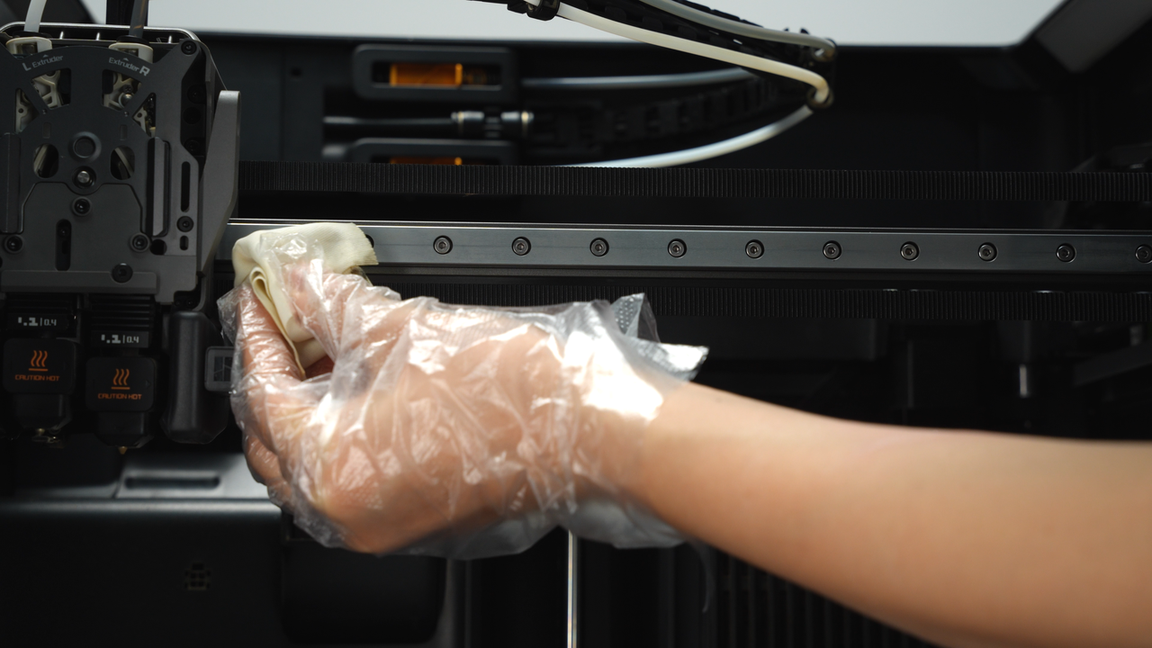
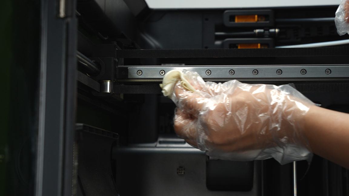
Use a non-woven cloth to wipe the X-axis assembly, and the belts can also be cleaned at the same time.
 |
 |
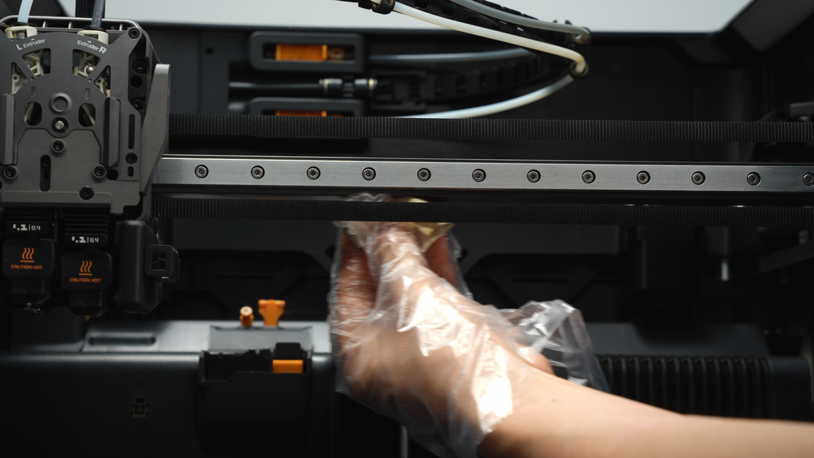
Then move the toolhead to the other side to expose the obscured section of the X-axis linear rail and perform the same cleaning operation.
 |
 |
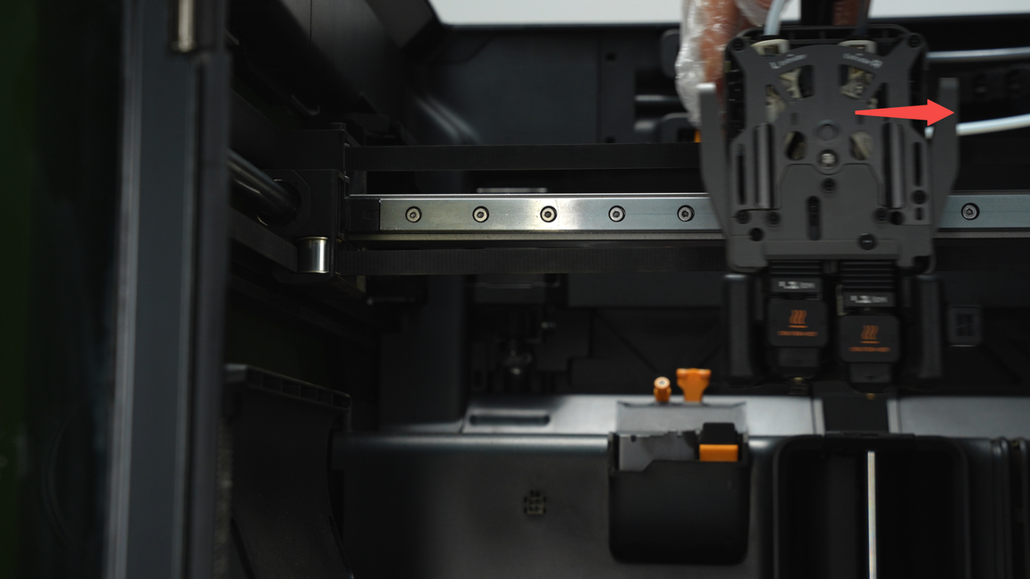
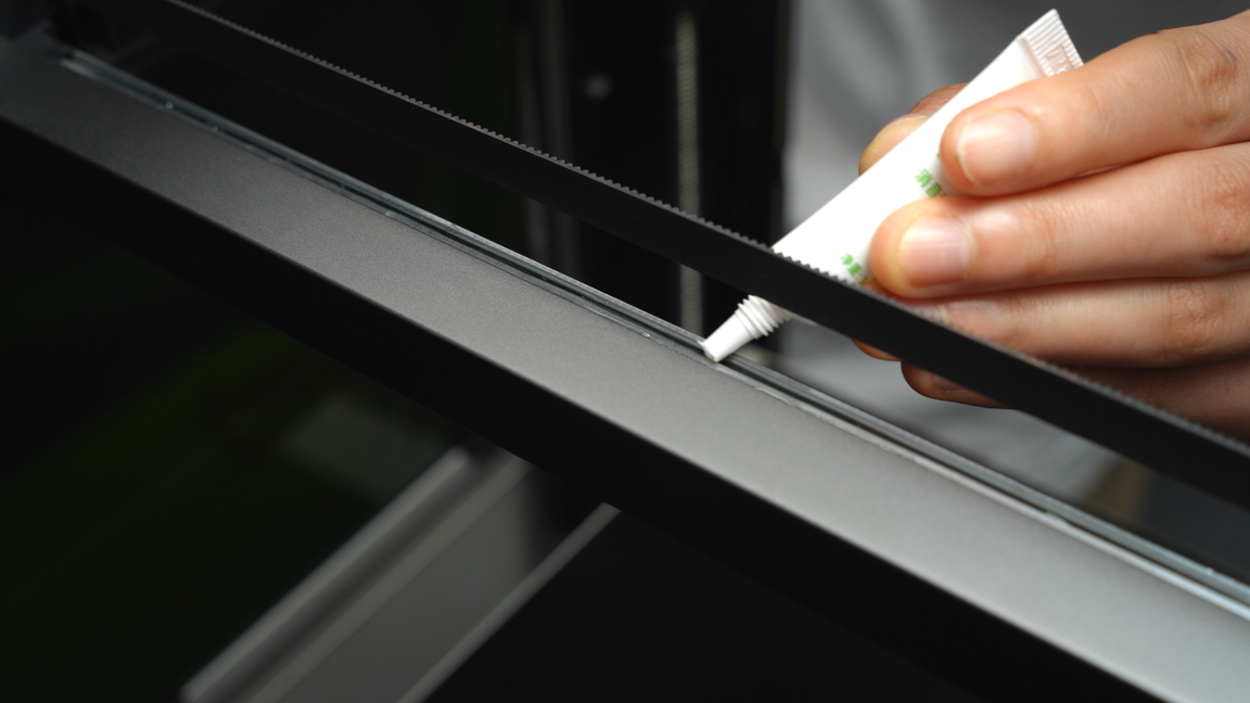
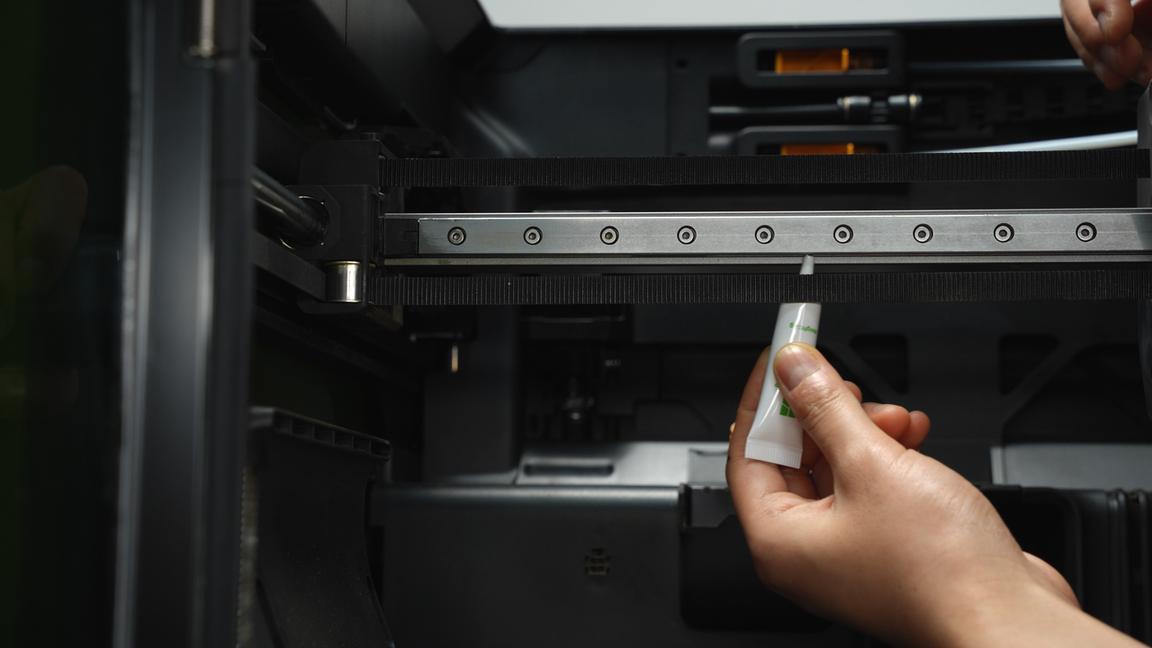
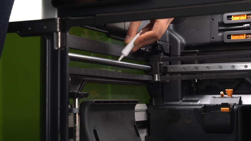
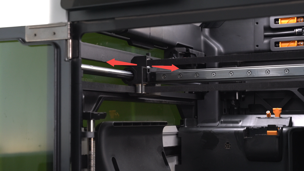
After cleaning the dust and debris from the surface of the X-axis assembly, it is recommended to apply lubricating oil to the rail and move the toolhead left and right to evenly distribute the oil on the rail. Please note that both the upper and lower sides of the rail need to be lubricated.
 |
 |
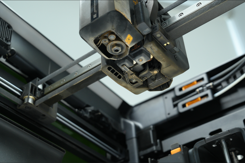
¶ Step8. Clean the nozzle camera and the toolhead camera
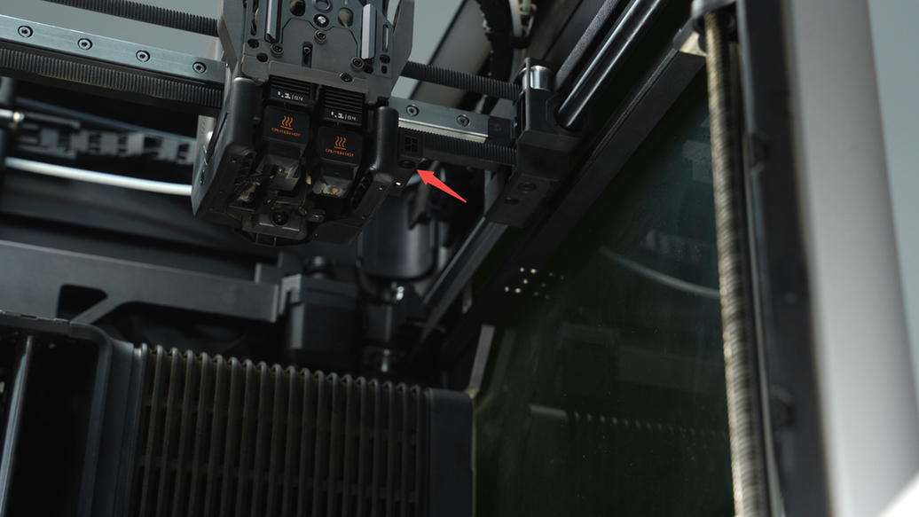
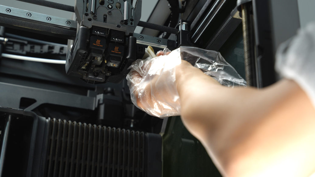
Clean the nozzle camera lens and the bottom of the toolhead with a non-woven cloth sprayed with alcohol, then move the flow blocker lever to clean the bottom of the other hotend.
 |
 |
 |
 |
After cleaning the nozzle camera, proceed to wipe the toolhead camera lens.
 |
 |
¶ Step9. Clean the flame sensor
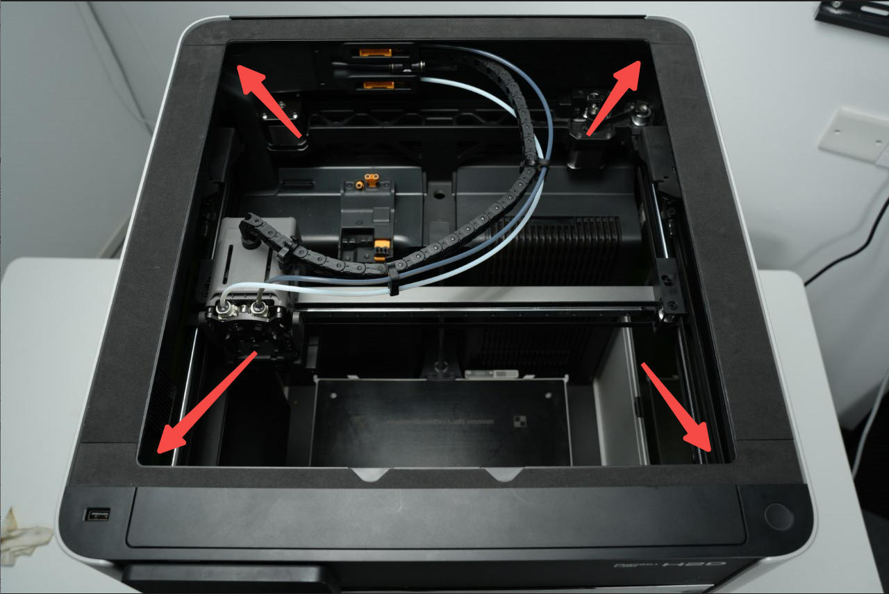
There are four flame sensors inside the printer, located at the four corners of the printer frame. Use a non-woven cloth to wipe each flame sensor.
 |
 |
 |
 |
 |
 |
¶ Step10. Clean the birdseye camera and the live camera
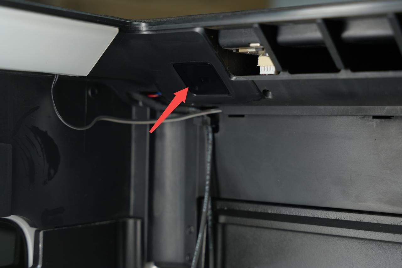
Use a non-woven cloth sprayed with alcohol to wipe the lenses of the birdseye camera and the live camera, ensuring thorough cleaning.
 |
 |
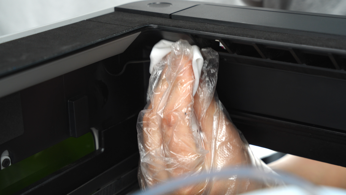
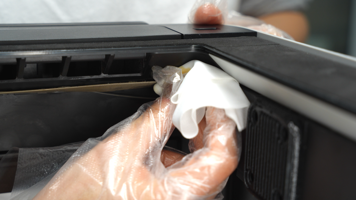
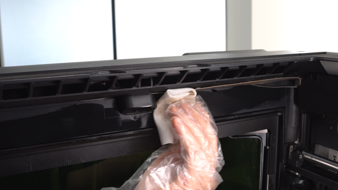
¶ Step11. Clean the inner side of the enclosure top frame
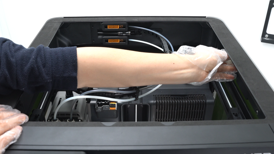
Use a non-woven cloth to clean the inner side of the enclosure top frame, ensuring to wipe all around. If certain areas are hard to reach, you can move the tool head aside for easier cleaning.
 |
 |
 |
 |
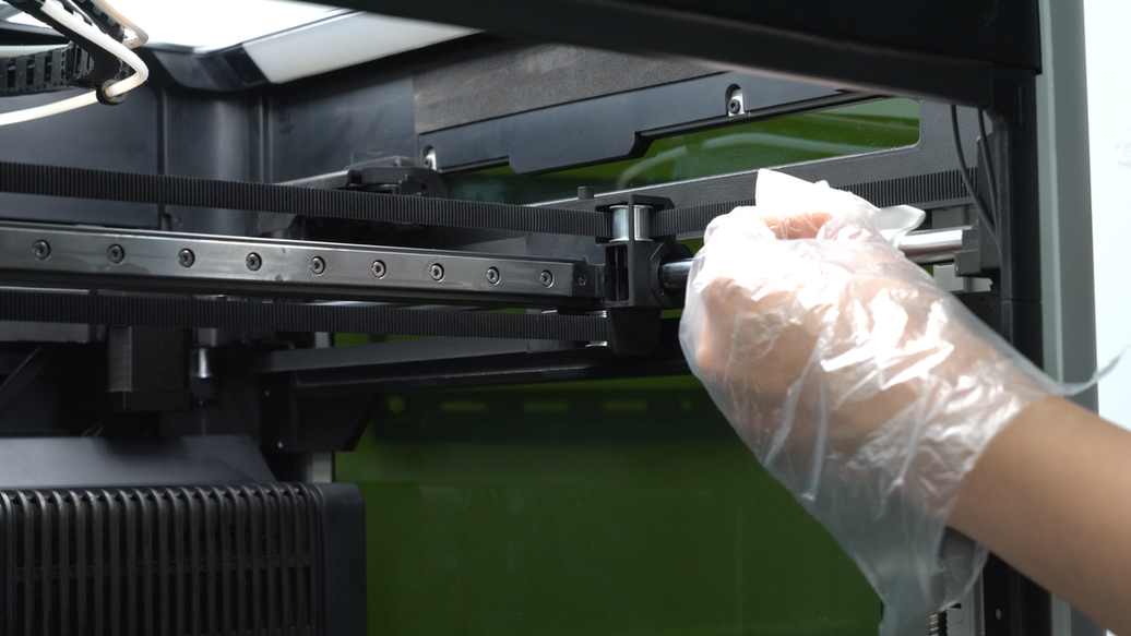
¶ Step12. Clean and lubricate the Y-axis linear rod
Clean the Y-axis linear rod with a non-woven cloth sprayed with alcohol, then move the toolhead to clean the obscured parts of the rod.
 |
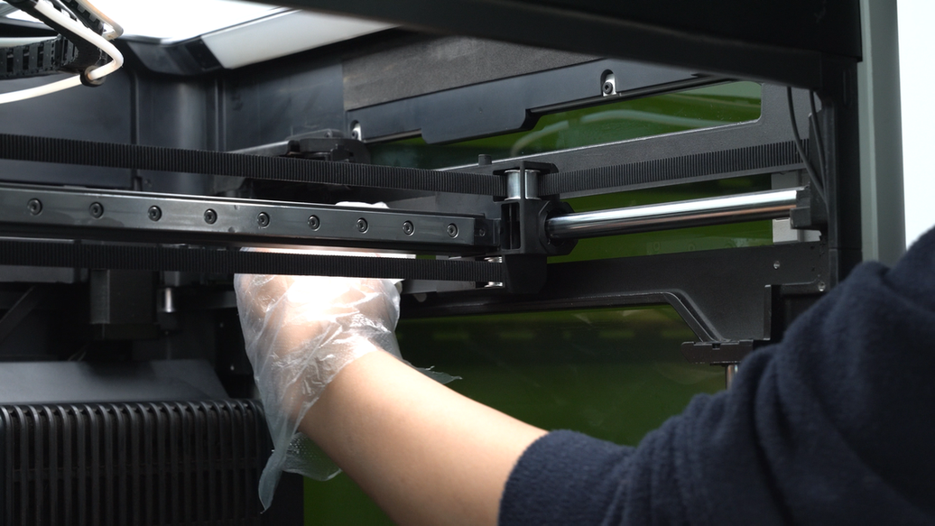 |
After thoroughly cleaning the linear rod, apply lubricating oil to it. Move the toolhead back and forth on the rod to evenly distribute the lubricating oil, ensuring thorough lubrication of the Y-axis linear rod.
 |
 |
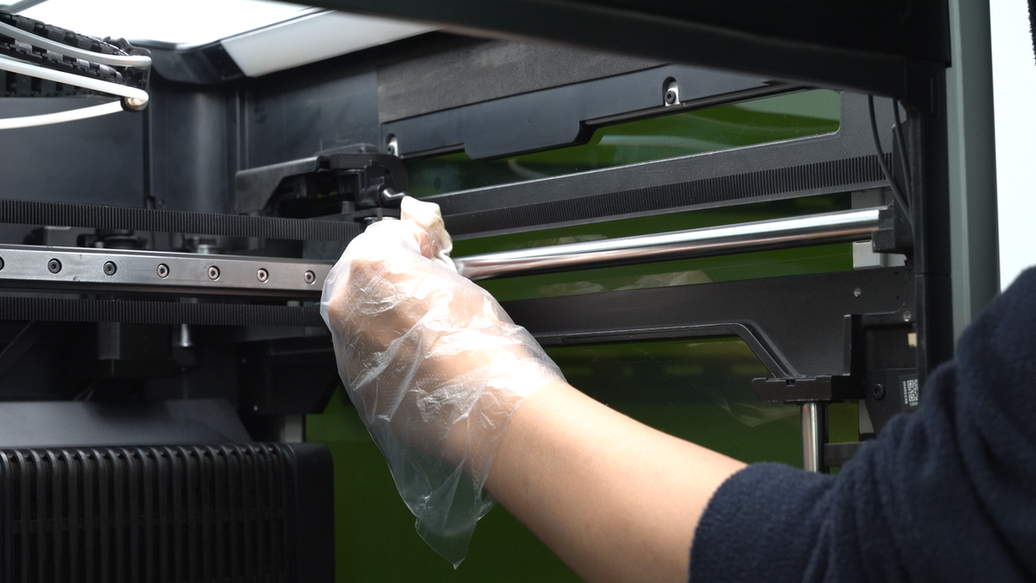
Next, use the same method to clean the other Y-axis linear rod.
 |
 |
 |
 |
¶ Step13. Clean the auxiliary part cooling fan and the left/right side panels.
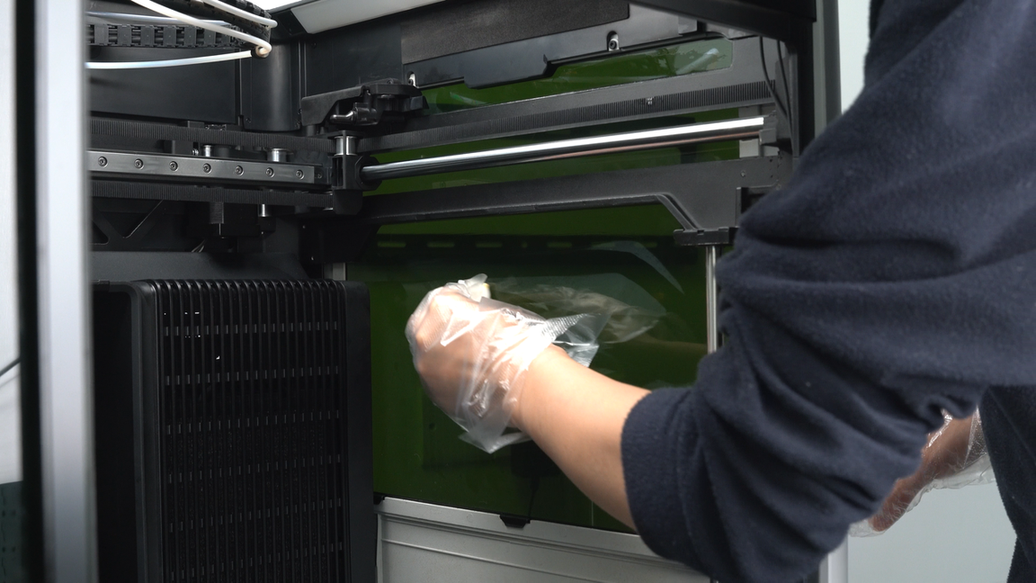
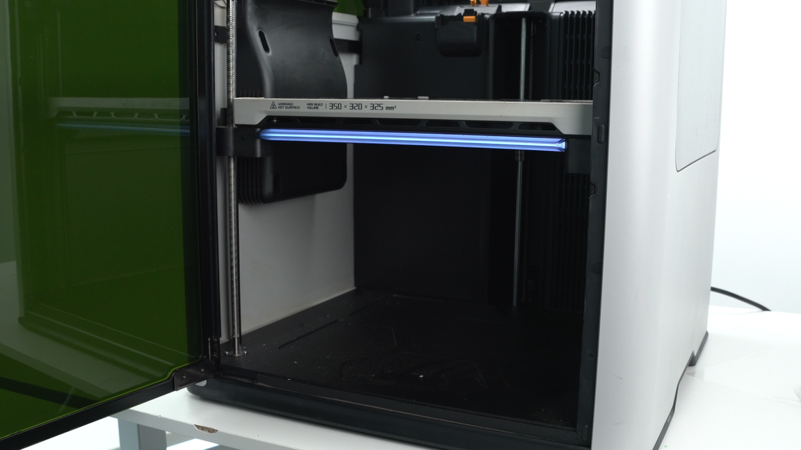
Clean the dust on the left side panel glass and the top of the auxiliary part cooling fan using a non-woven cloth sprayed with alcohol. Then, wipe the surface and sides of the auxiliary part cooling fan. The top of the auxiliary part cooling fan has a shock absorption structure, so when cleaning, try not to pull forcefully outward to prevent the shock-absorbing pins from falling off.
 |
 |
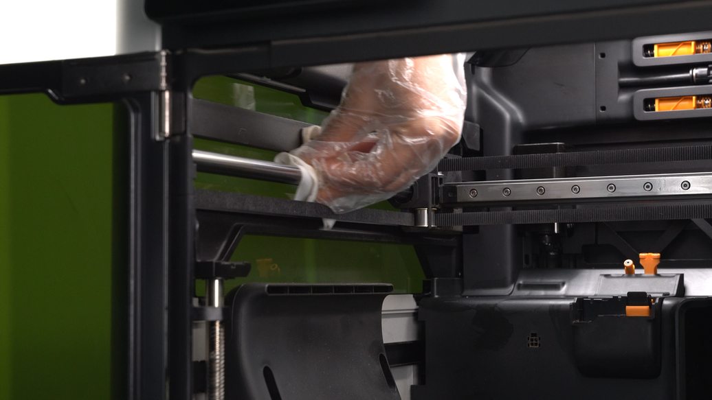
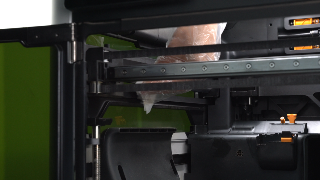
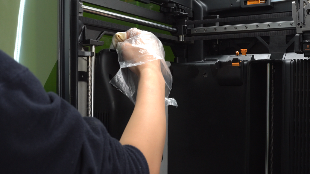
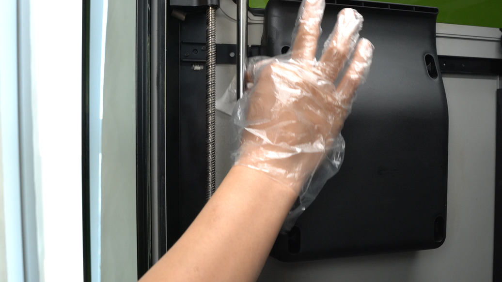
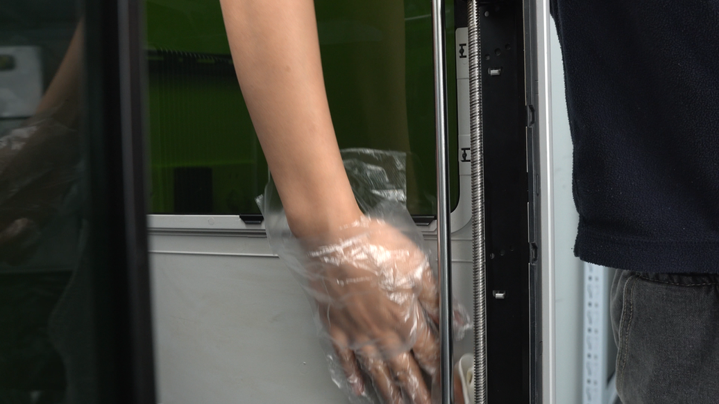
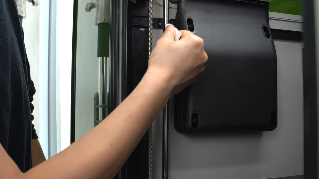
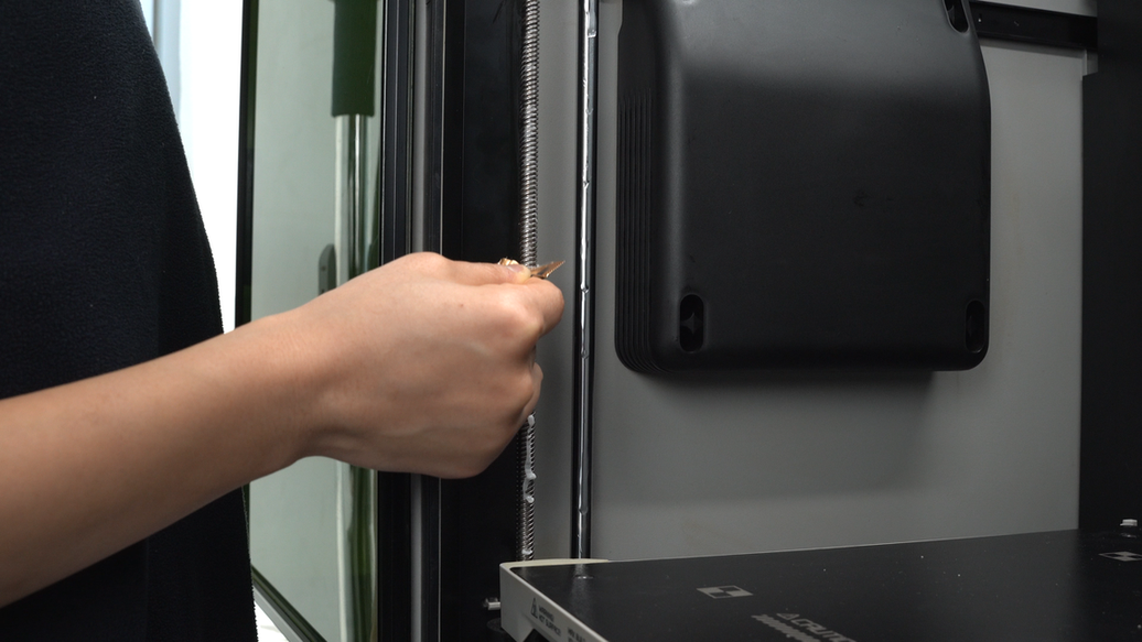
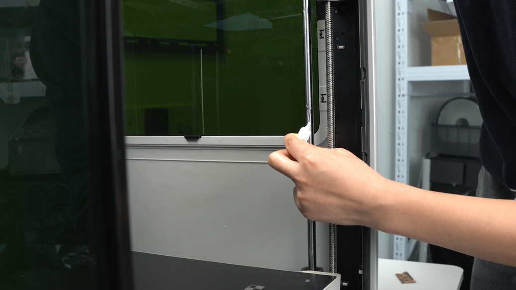
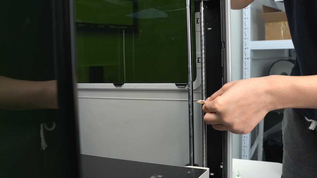
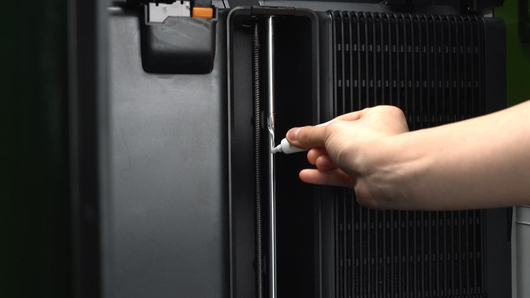
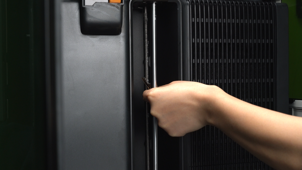
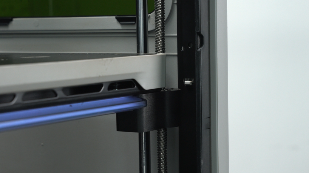
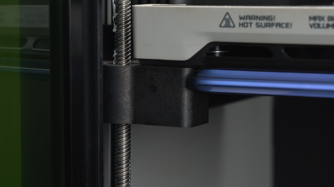
Next, wipe the inner surface of the left side panel to remove the dust. The inner surface obscured by the leadscrew may be difficult to clean thoroughly. You can grip the non-woven cloth, insert it into the gap of the leadscrew, and then wipe the surface of the left side panel.
 |
 |
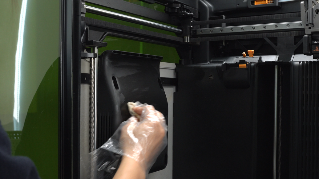
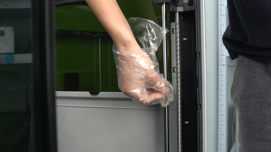
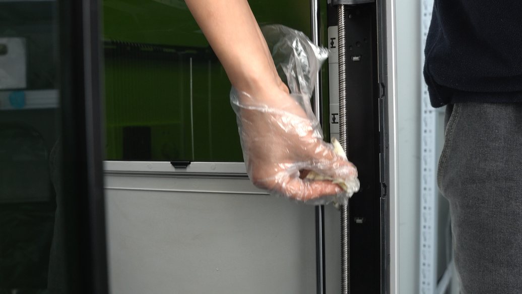
For the right side panel, perform the same cleaning procedure. Wipe the right side glass and the inner surface of the right side panel with a non-woven cloth sprayed with alcohol to remove the dust.
 |
 |
¶ Step14. Clean and lubricate the Z-axis linear rod and leadscrew
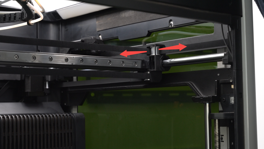
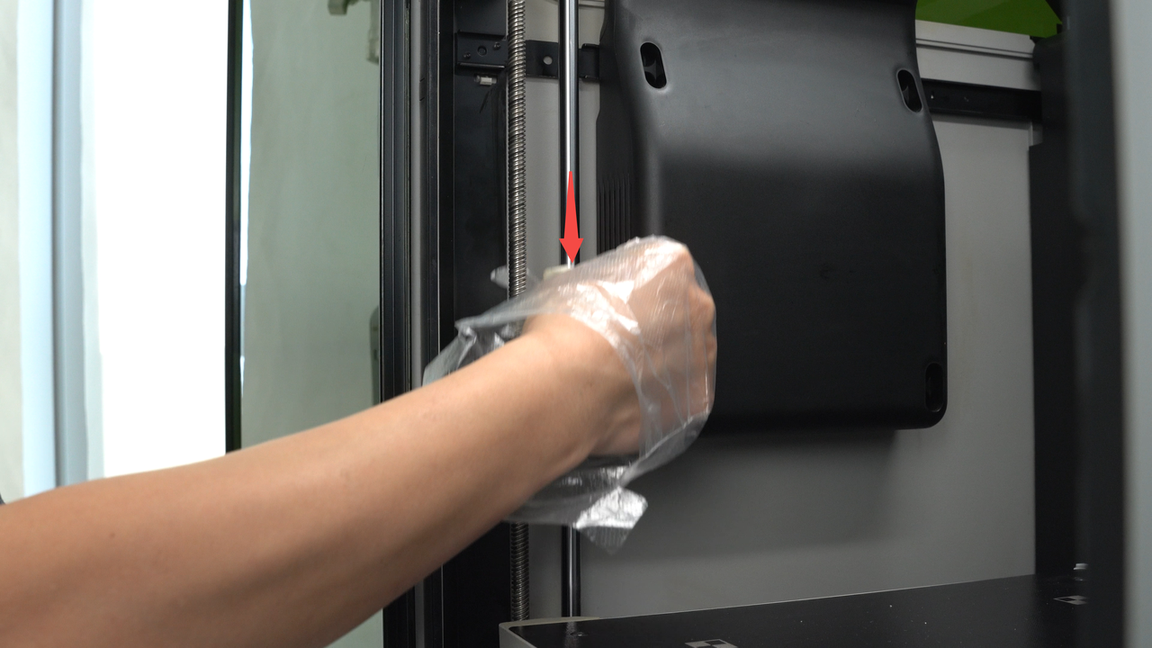
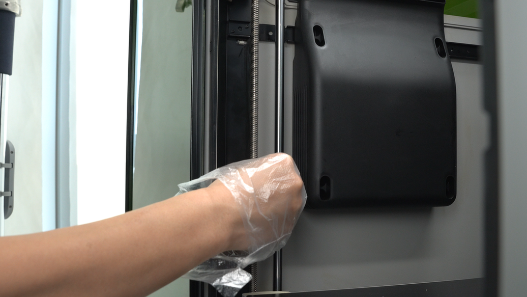
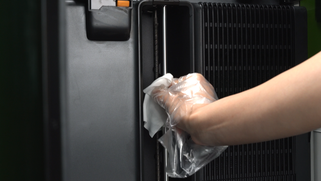
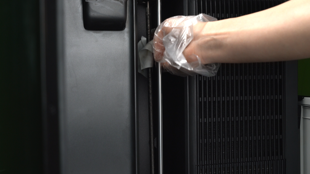
Wrap a non-woven cloth around the Z-axis linear rod, move it up and down to wipe and ensure the linear rod is cleaned thoroughly. Then, use the same motion to wipe the lead screw.
 |
 |
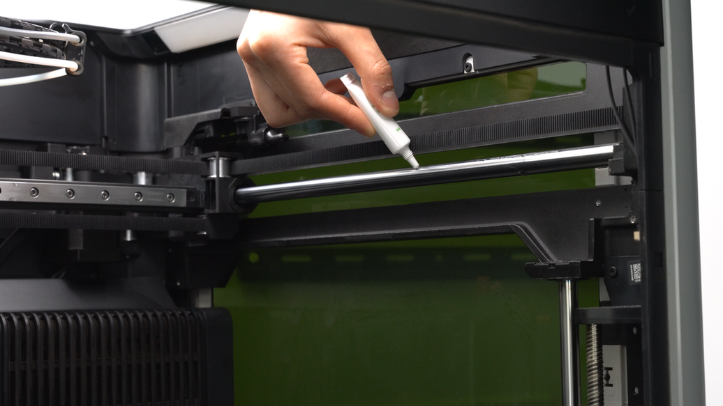
Next, apply lubricating oil to the linear rod and lubricating grease to the lead screw. Please ensure not to mix up the lubricating oil and grease.
 |
 |
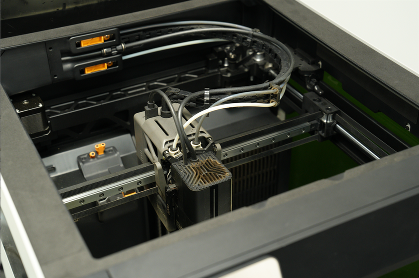
In addition to the linear rod and leadscrew on the left side, there are also linear rods and leadscrews on the right side and the inner side inside the H2D, totaling 3 sets. The same cleaning and lubrication procedures need to be carried out for the other 2 sets of linear rods and leadscrews as well.
The following images show the cleaning and lubrication process for the linear rods and leadscrews on the right side.
 |
 |
 |
 |
The following images show the cleaning and lubrication process for the linear rods and lead screws on the inner side.
 |
 |
 |
 |
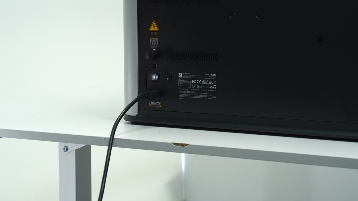
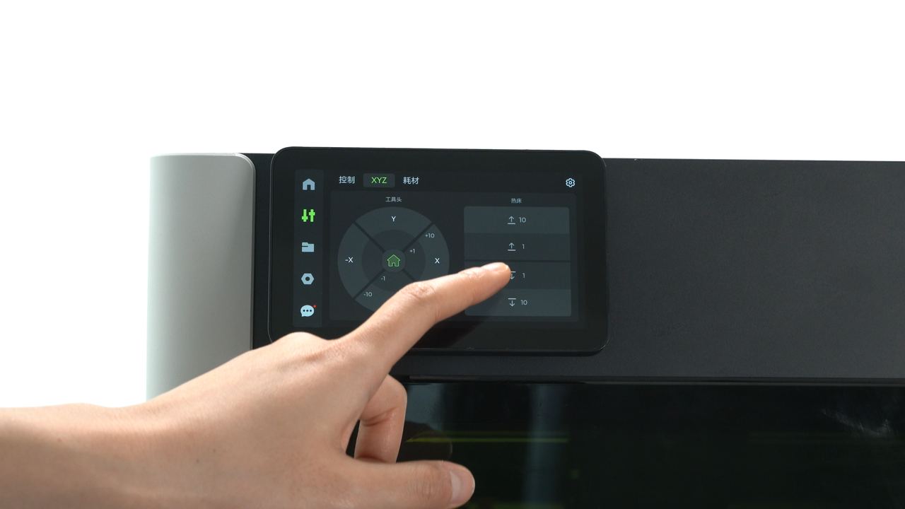
Once lubrication is complete, power up the printer again and control the movement of the heatbed up and down on the printer screen. This is to ensure that the lubricating oil and grease fully penetrate the Z-axis leadscrews and linear rods, guaranteeing adequate lubrication.
 |
 |
 |
 |
Before continuing with the cleaning and maintenance work, please turn off the printer again.

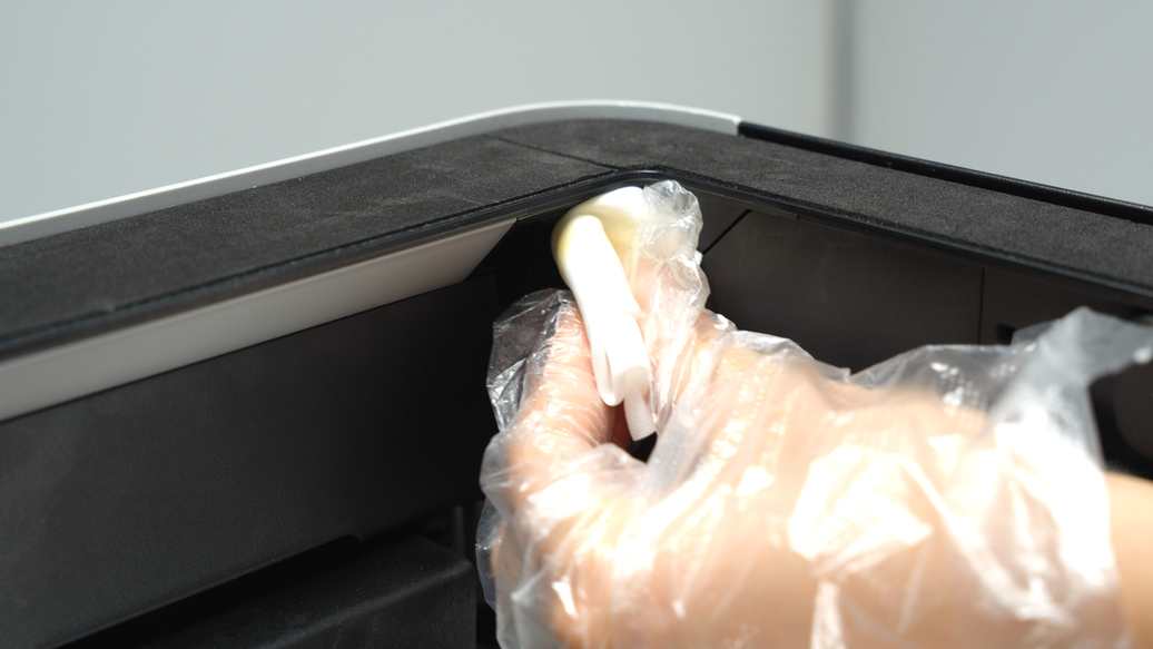
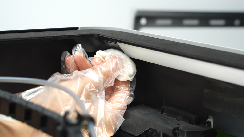
¶ Step15. Clean the surface of the left inner lining and the upper side of the left and right inner linings
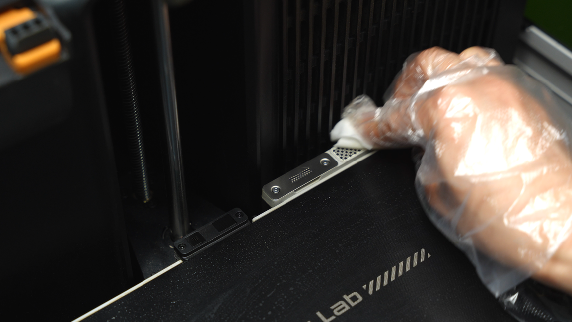
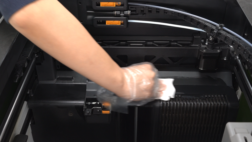
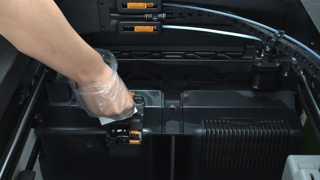
Clean the upper surfaces of the left and right inner linings as well as the surface of the left inner lining using a non-woven cloth sprayed with alcohol. Also, wipe the purge wiper to remove any remaining filaments.
 |
 |
¶ Step16. Clean the activated carbon air filter cover
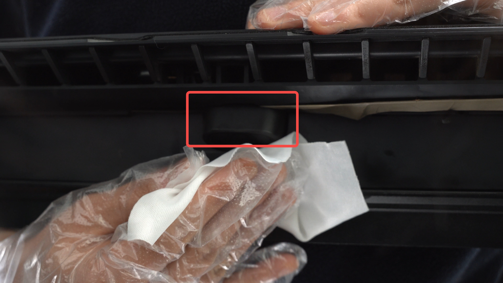
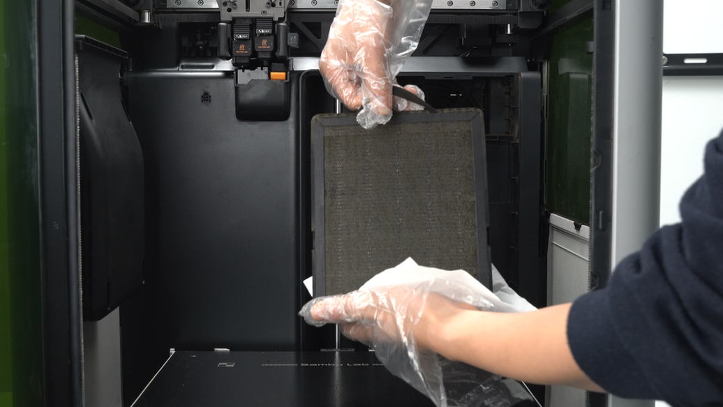
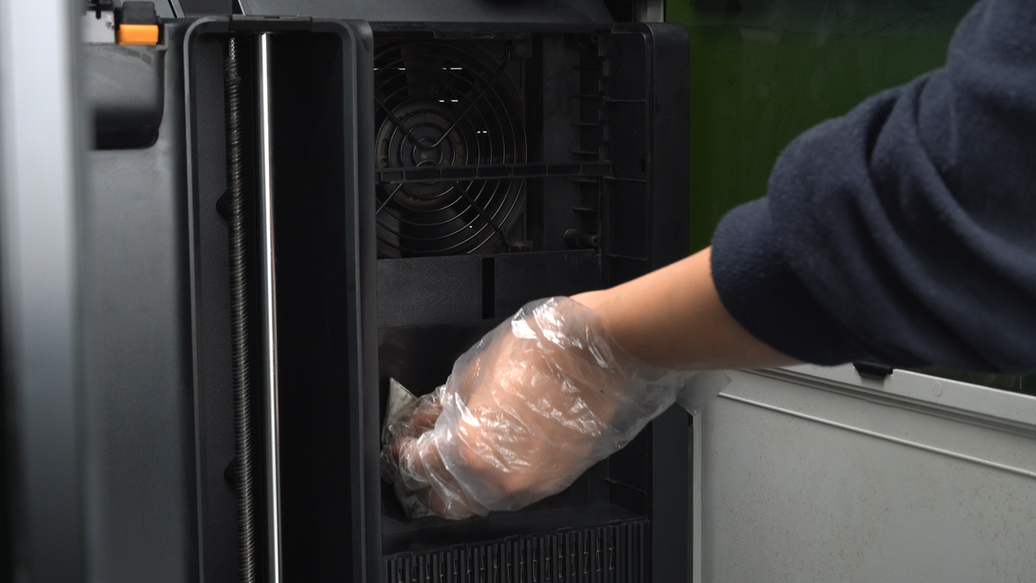
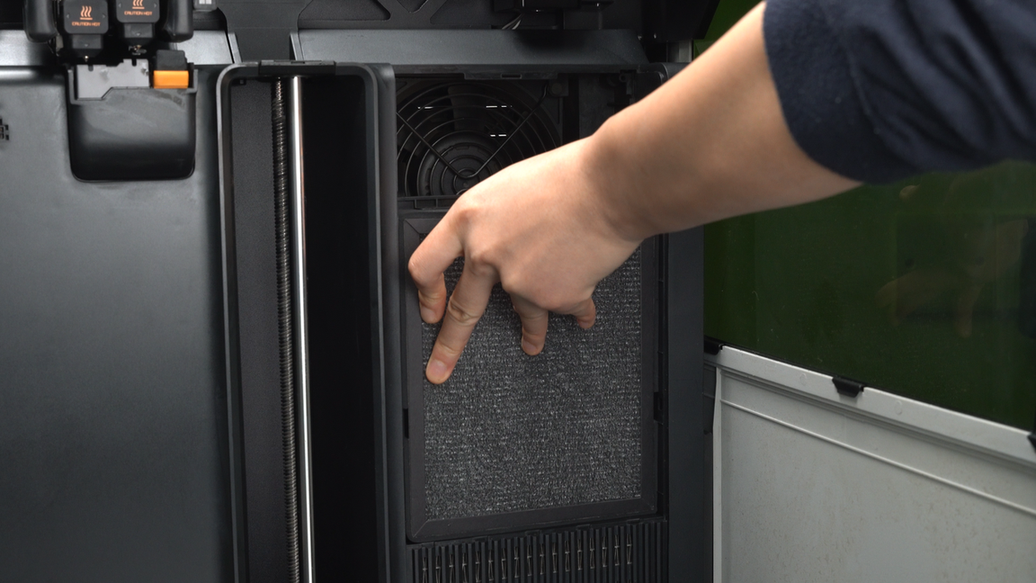
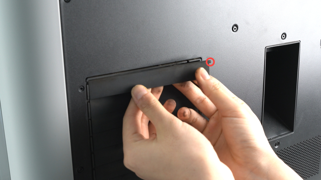
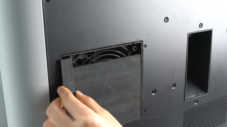
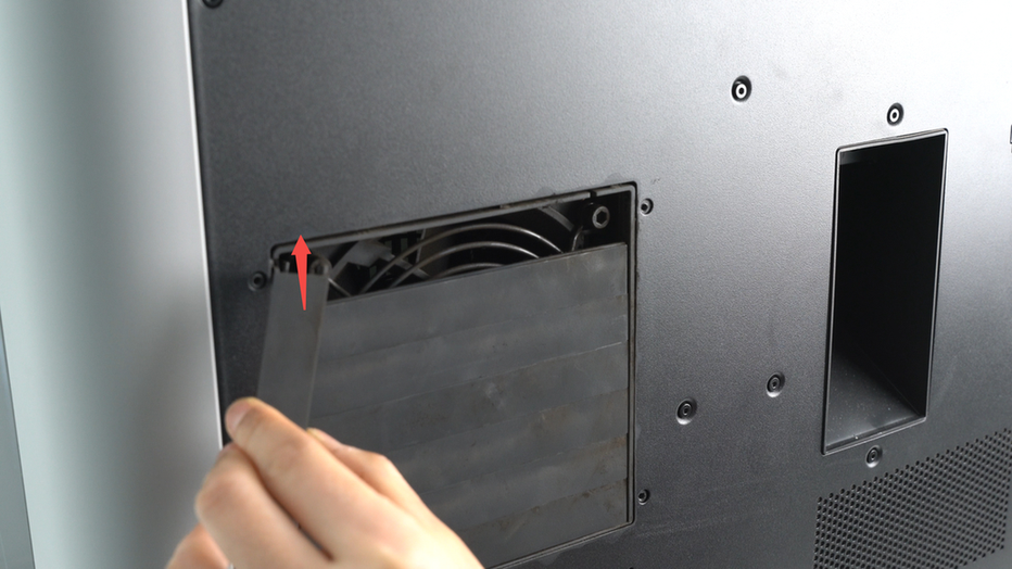
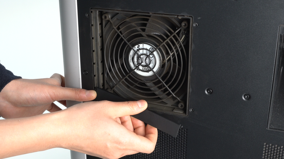
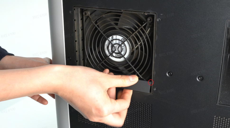
Press down on the top of the activated carbon air filter cover with your hand, pull the cover outward to unlock the top buckle, and remove the activated carbon air filter cover. When removing the air filter, place a piece of paper under the air filter to prevent dust from falling into the printer's interior.
 |
 |
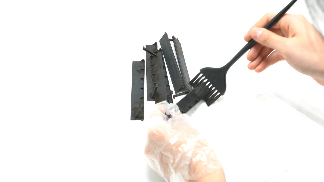
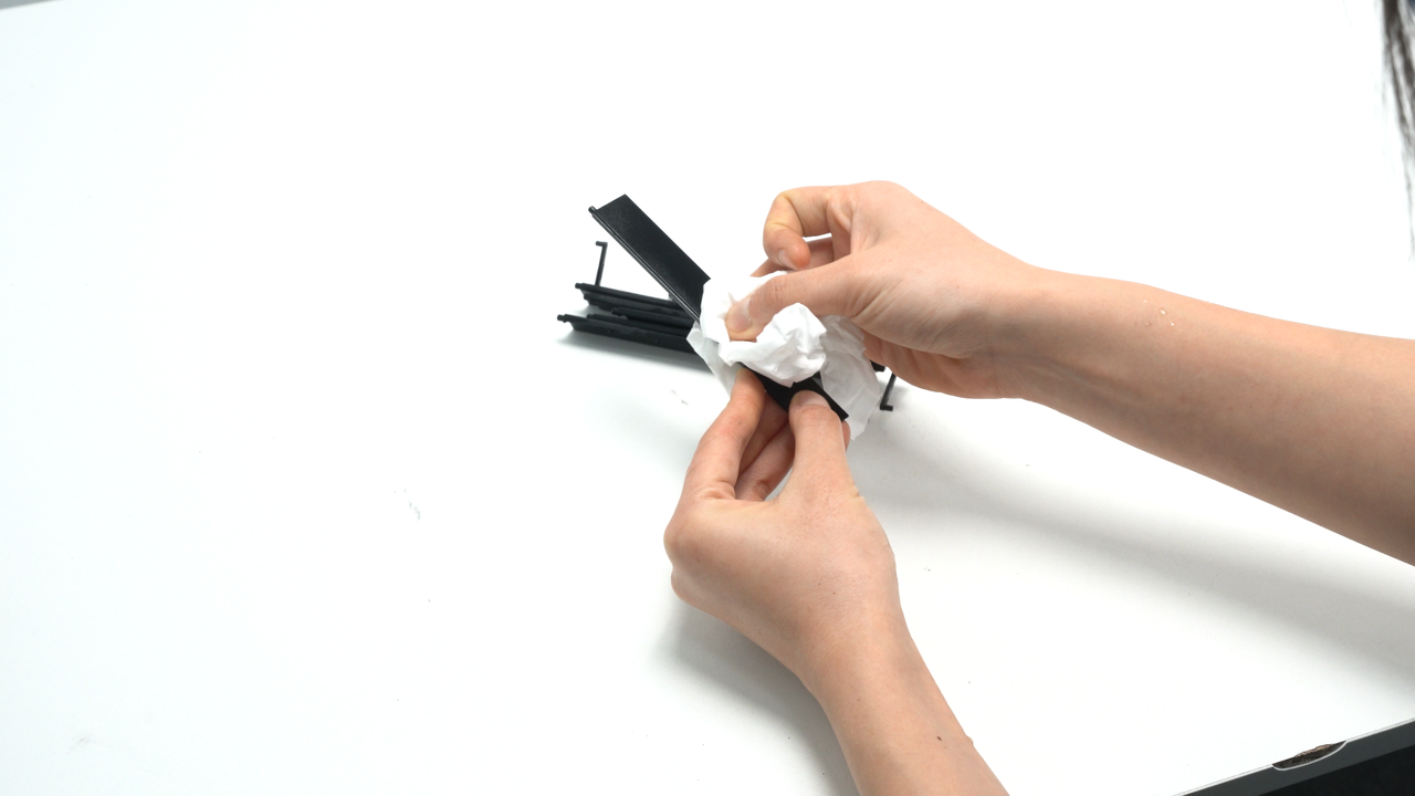
Brush off the dust from both sides of the filter cover, then use a non-woven cloth sprayed with alcohol to wipe the filter cover clean.
 |
 |
 |
 |
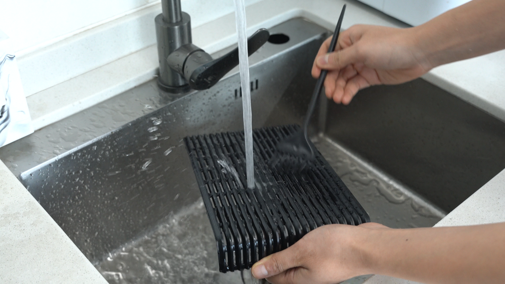
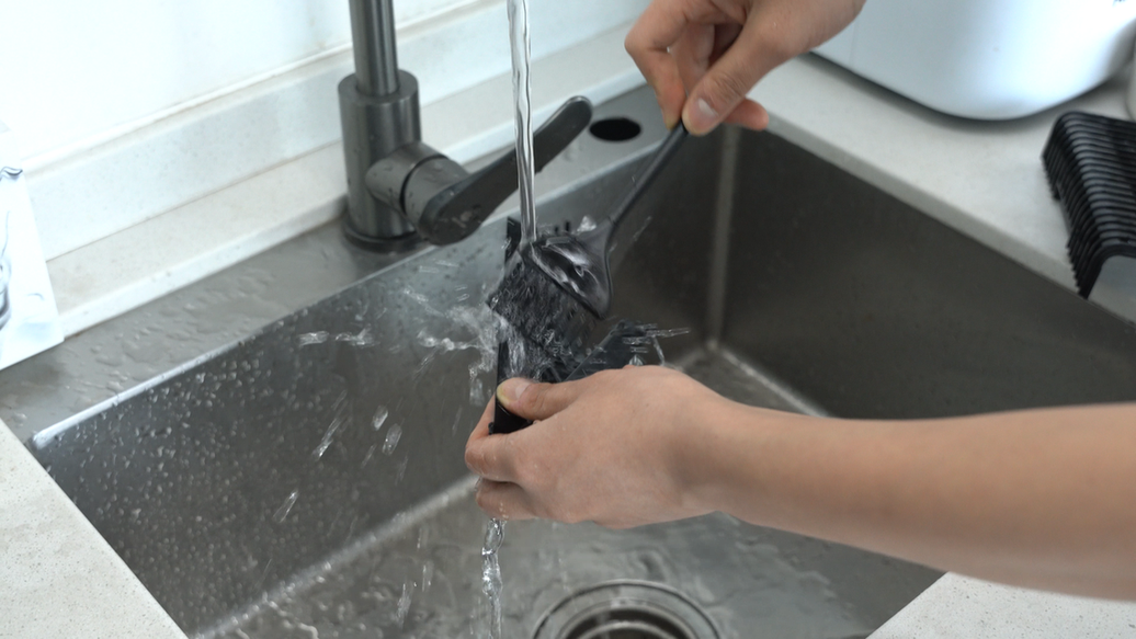
If the filter cover is heavily soiled and normal methods are not effective in cleaning it, you can try rinsing the filter cover directly under the tap while using a brush for cleaning. Please note that after washing with water, make sure to completely dry the filter cover. There are some electronic components around the filter cover, and residual moisture may affect the functionality of these electronic components.
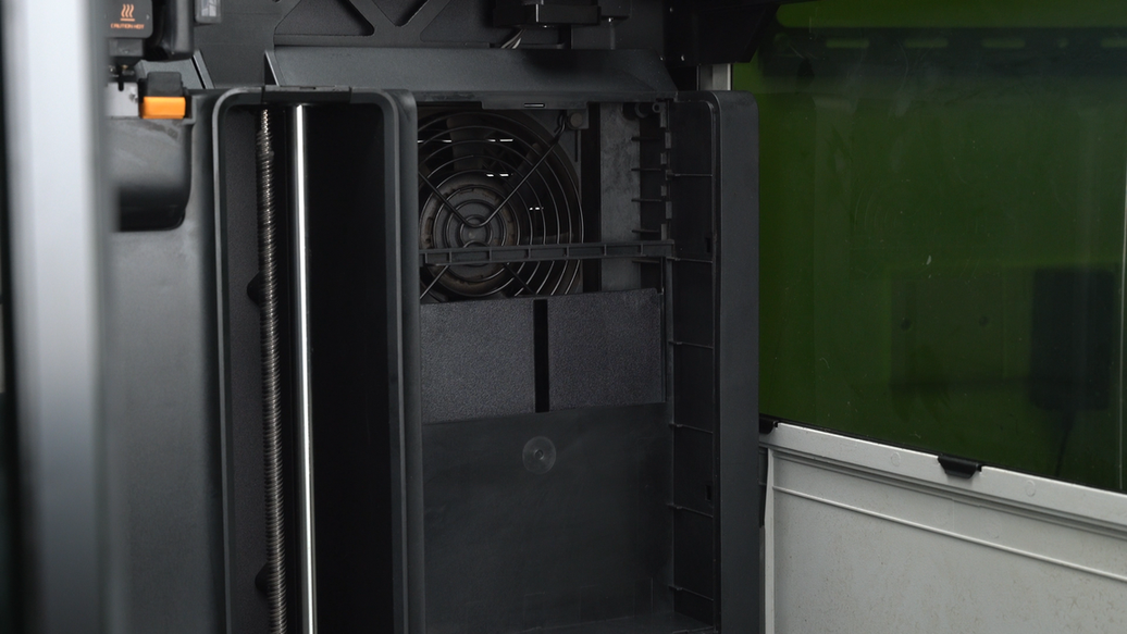
¶ Step17. Clean the interior of the chamber exhaust fan and the right inner lining
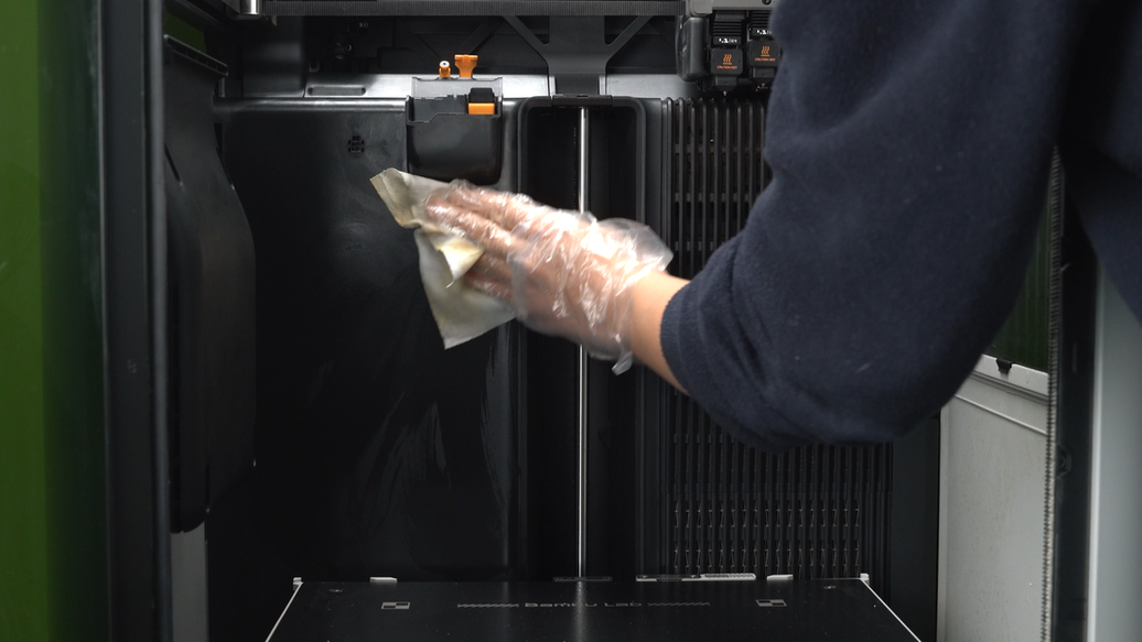
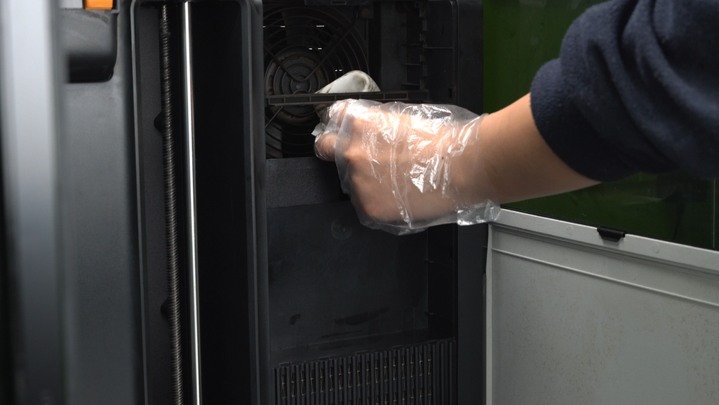
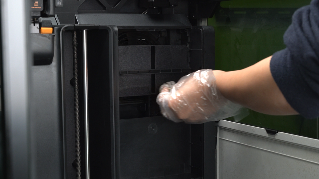
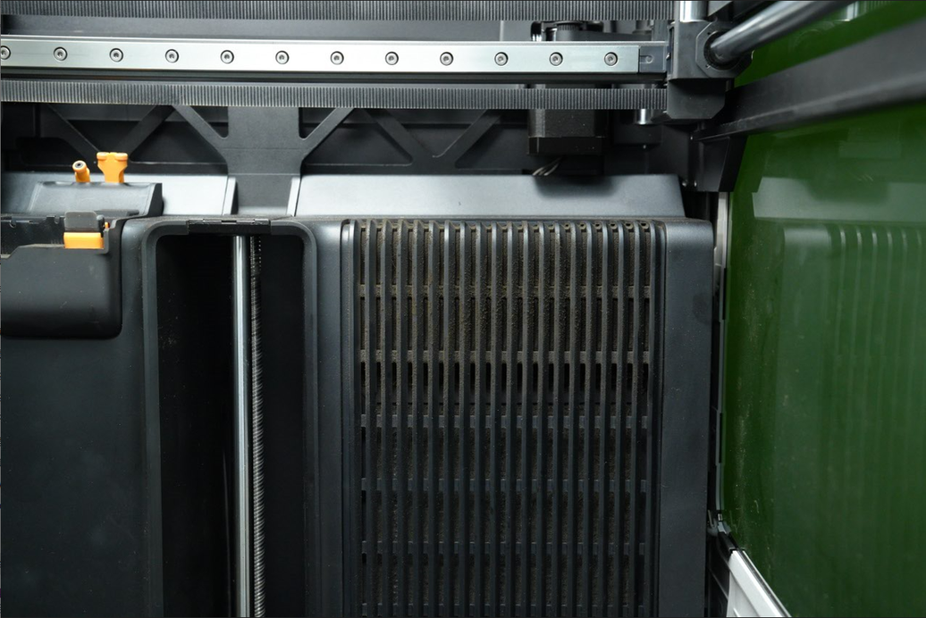
Wipe the activated carbon filter slot inside the right inner lining with a non-woven cloth sprayed with alcohol.
 |
 |
 |
 |
Then move the filter switch flap upwards to clean the lower part of the flap. Once cleaning is finished, move the filter switch flap down. When cleaning the filter switch flap, frequent up and down movements may reduce the lifespan of the servo motor, so try to minimize the number of times the flap is pushed and pulled.
 |
 |
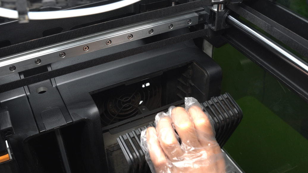
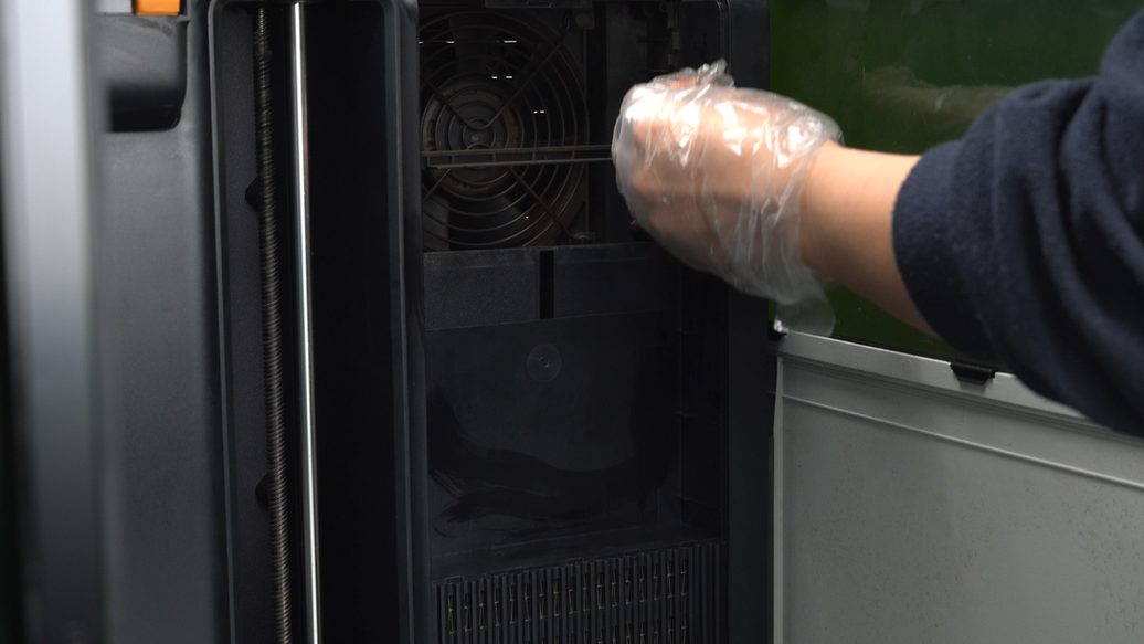
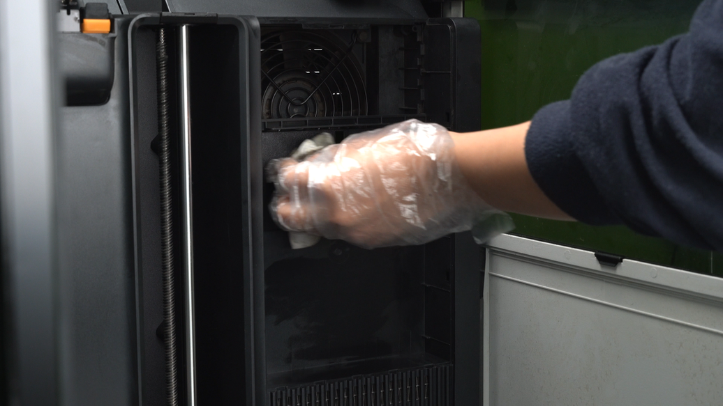
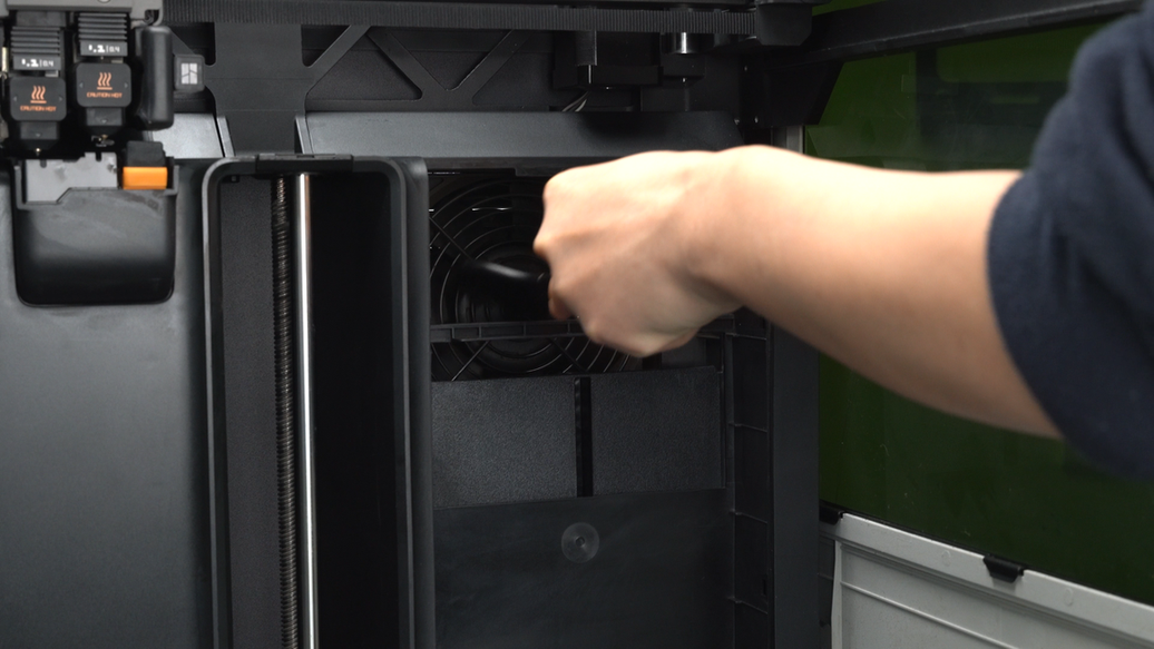
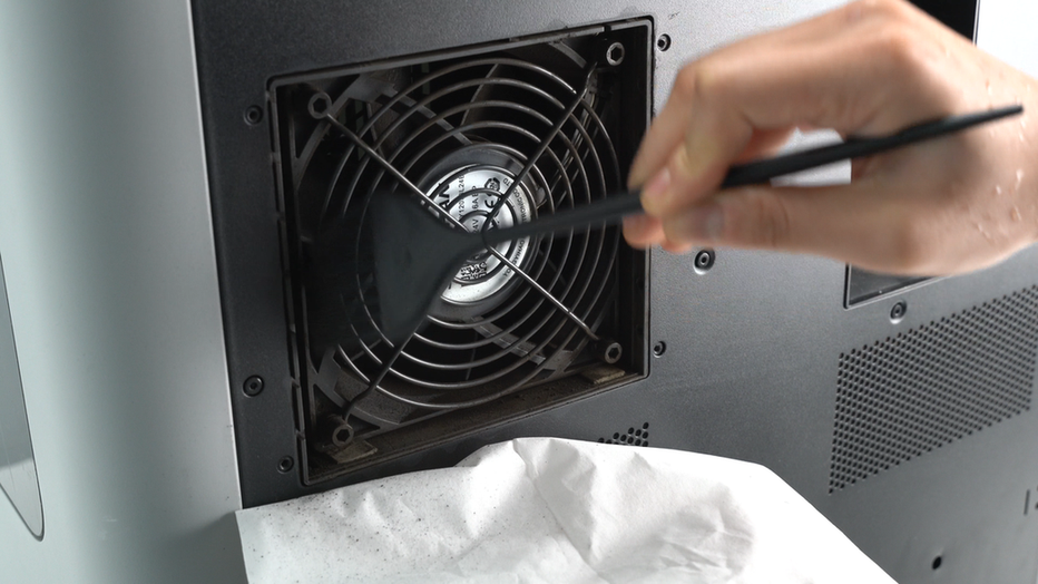
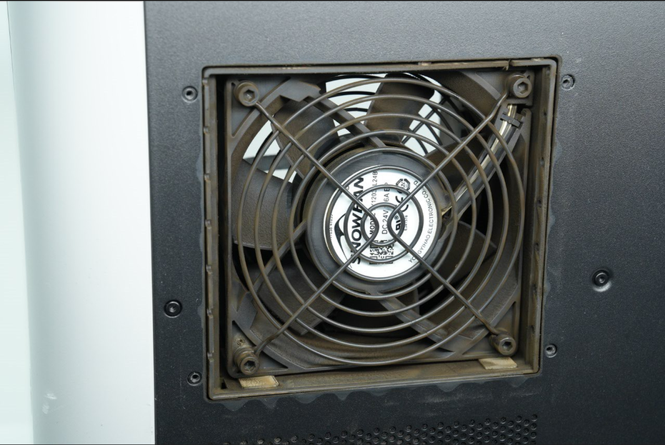
Next, clean the chamber exhaust fan with a brush, moving the fan blades to clean the dust on each blade.
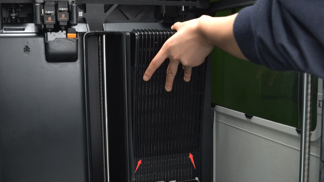
After cleaning is completed, install the new activated carbon filter into the right inner lining of the printer. Then, insert the activated carbon filter cover diagonally into the inner lining, with the five bottom pins inserted into the inner lining. Push the activated carbon filter cover inward, ensuring the top four buckles and one stopper are securely fastened inside the inner lining.
 |
 |
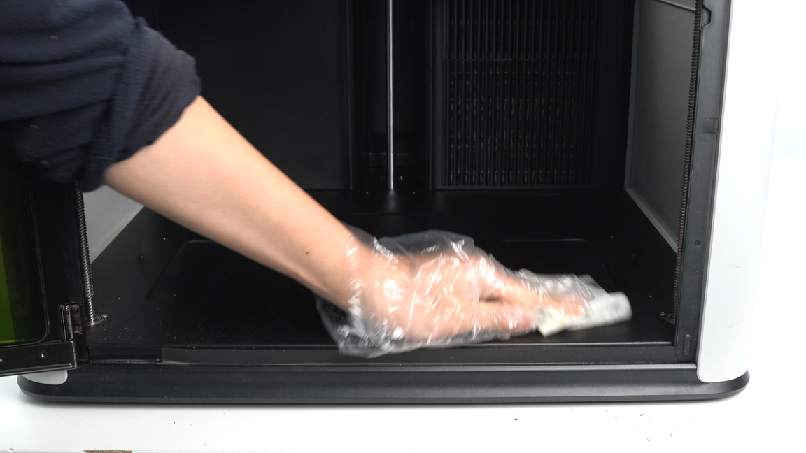
¶ Step18. Clean the bottom of the printer chamber
Clean the dust and foreign objects at the bottom of the printer.
¶ Step19. Clean the chamber exhaust
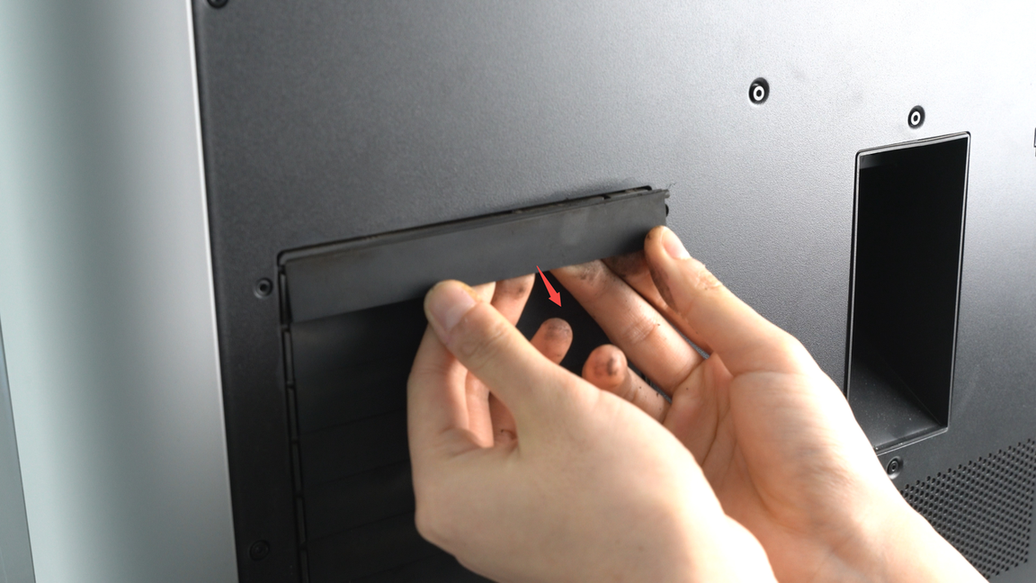
The chamber exhausts are located on the outer side of the chamber exhaust fan, with a total of 7 chamber exhausts. When removing the chamber exhausts, disassemble them from top to bottom. Apply slight pressure to push the chamber exhausts outward slightly, then remove the locating block from the small hole on the right side. Rotate the chamber exhausts 90° clockwise, lift it up slightly, and smoothly remove the pin to detach the chamber exhausts. Repeat the same steps to remove the remaining 6 chamber exhausts.
 |
 |
 |
 |
Then start by brushing off the dust on the chamber exhausts, then wiping them with a non-woven cloth sprayed with alcohol.
 |
 |
If the chamber exhausts are heavily soiled and normal methods are not effective in cleaning them, you can try rinsing the chamber exhausts directly under the tap while using a brush for cleaning. Please note that after washing with water, make sure to completely dry the chamber exhausts. There are some electronic components around the chamber exhausts, and residual moisture may affect the functionality of these electronic components.
¶ Step20. Clean the exterior of the chamber exhaust fan
After removing the chamber exhausts, use a brush to clean the dust on the exterior of the fan.
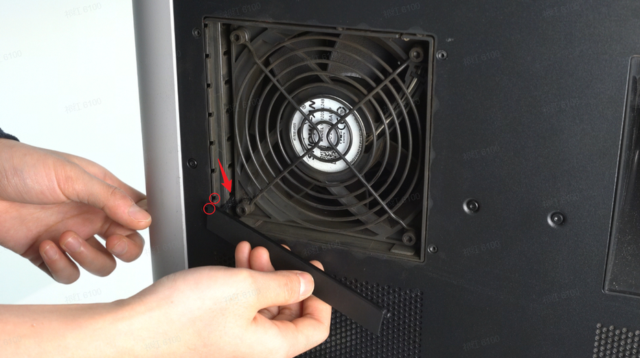
After cleaning, when installing the chamber exhausts, start from the bottom and work your way up. Begin on the left side by inserting the left pin into the hole indicated by the arrow, aligning the left location block with the small hole shown by the circle, and snapping it into place. Then, insert the right location block into the small hole on the right side. Follow the same steps to install the remaining 6 chamber exhausts.
 |
 |
¶ Appendix
¶ Instructions for Cleaning Agents
During the above maintenance process, it is recommended to use alcohol (75% ethanol or 70% isopropanol) and non-woven cloth to wipe the surfaces of components such as camera lenses, metal, and plastic. For specific areas like filter covers, grilles, fan blades, and heat sinks, it is recommended to use a brush for cleaning.
After using liquid cleaning agents, please slightly wring the non-woven cloth dry before cleaning. Additionally, we strongly recommend increasing the cleaning frequency to prevent oil stains buildup that may become difficult to remove.
If the contamination is severe, a degreaser similar to Mr. Muscle should be used for deep cleaning.
¶ Maintenance and Replacement of Vulnerable Consumables
| Vulnerable Consumables | Replacement method | Recommended replacement frequency | Precautions | Damage diagram |
|---|---|---|---|---|
| Filament cutter | Replace H2D Filament Cutter Lever and Blade | For regular filaments like PLA/PETG/ABS/PC, the blade should be checked every 3-5 rolls. If the blade is dull, replace it.For abrasive filaments like PA+CF/PA+GF, the cutter can get dull much quicker, so we recommend checking it after printing 1-2 rolls of abrasive materials. If the blade is dull, replace it. | ||
| Extruder gear | Disassemble and install the H2D extruder | You should clean the dust inside the extruder when you can see small amounts of dust on the extruder gear. We recommend checking and cleaning the extruder gear assembly once a week. If any wear is observed on the extruder gear, it should be replaced. | ||
| Nozzle wiper | Replace H2D Nozzle Wiping Pad | If you find that the nozzle wiper is damaged or deformed, you need to replace it to ensure the nozzle cleaning effect | ||
| Hotend silicone sock | Replace H2D Hotend | The silicone sock should be replaced if wear signs are present on it, or if the silicone sock doesn't remain attached securely to the hotend. | ||
| Hotend | Replace H2D Hotend | Under normal circumstances, for printing non-carbon fiber filaments like PLA and PETG, it is advisable to clean the nozzle every 5 spools. When printing with carbon fiber filaments, clean the nozzle every 2 spools. If you find that the nozzle is obviously worn causing material leakage, and cleaning the nozzle does not improve the extrusion, please replace it with a new spare hot end. |
¶ Possible consequences of not performing maintenance
The printer used in this tutorial is a non-production prototype equipped with a 10W laser module that underwent 40 hours of continuous aging testing (i.e., continuous laser tasks for 40 hours) without timely cleaning. The purpose is to demonstrate cleaning steps and precautions. If the appearance of this printer differs from yours, please refer to the appearance of the printer you received.
 |
 |
 |
 |
 |
 |
¶ End Notes
We hope the detailed guide provided has been helpful and informative.
If this guide does not solve your problem, please submit a technical ticket, we will answer your questions and provide assistance.
If you have any suggestions or feedback on this Wiki, please leave a message in the comment area. Thank you for your support and attention!