¶ Applicable models of printers
P1P/P1S
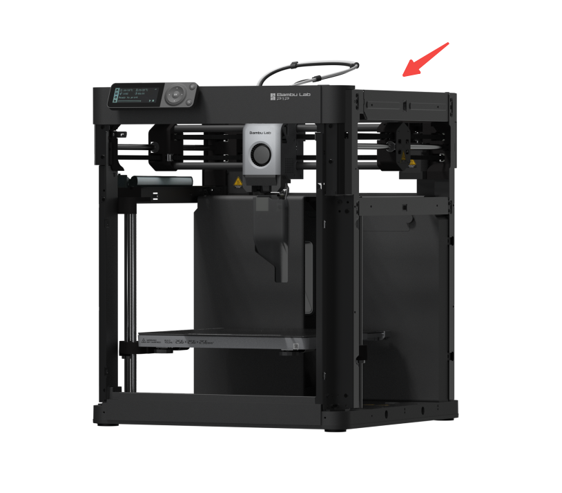
¶ Core XY Movement System
The Core XY Movement System is installed on the top of the printer to allow the toolhead to move in the X/Y direction.
 |
 |
The replacement of this component is quite challenging. It is recommended to carefully read this replacement guide before proceeding with the replacement.
Since a large number of screws are involved in the process, it is advisable to prepare some small boxes in advance to store different screws separately.
¶ When to use?
- The idler pulley makes noise or is damaged.
- The core XY movement system is bent and deformed.
- The Y-axis linear bearing is damaged.
- The Y-axis linear rod is damaged.
¶ Safety Warning
IMPORTANT!
It's crucial to power off the printer before conducting any maintenance work, including work on the printer's electronics and tool head wires. Performing tasks with the printer on can result in a short circuit, leading to electronic damage and safety hazards.
During maintenance or troubleshooting, you may need to disassemble parts, including the hotend. This exposes wires and electrical components that could short circuit if they contact each other, other metal, or electronic components while the printer is still on. This can result in damage to the printer's electronics and additional issues.
Therefore, it's crucial to turn off the printer and disconnect it from the power source before conducting any maintenance. This prevents short circuits or damage to the printer's electronics, ensuring safe and effective maintenance. For any concerns or questions about following this guide, open a new ticket in our Support Page and we will do our best to respond promptly and provide the assistance you need.
¶ Tools and materials needed
- New Core XY Movement System - Please open a new ticket in our Support Page to order the part.
- H2.0 Allen key
- H1.5 Allen key
- Estimated time required: 3 - 4 hours
¶ Remove the core XY movement system
¶ Step 1:Remove the screen and front cover
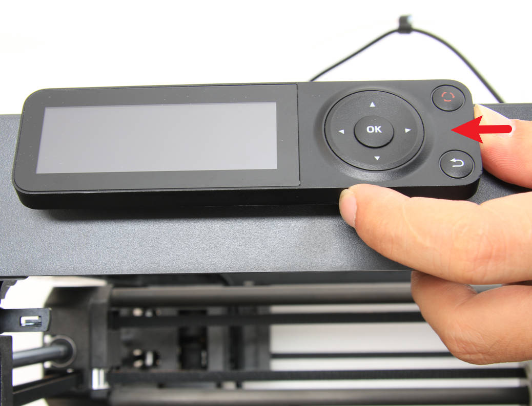
- Remove the screen
Press the buckle under the screen to release the lock, then push the screen to the right to loosen it; then disconnect the screen cable (the screen cable can remain on the AP board and be removed together with the AP board):
 |
 |
You can refer to the following Wiki for detailed steps on how to replace the screen of a P1P/P1S:
Screen
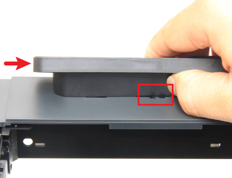
- Remove the front cover
Since the subsequent disassembly and installation of the left and right panels requires the removal of the front cover first, you can remove the front cover first.
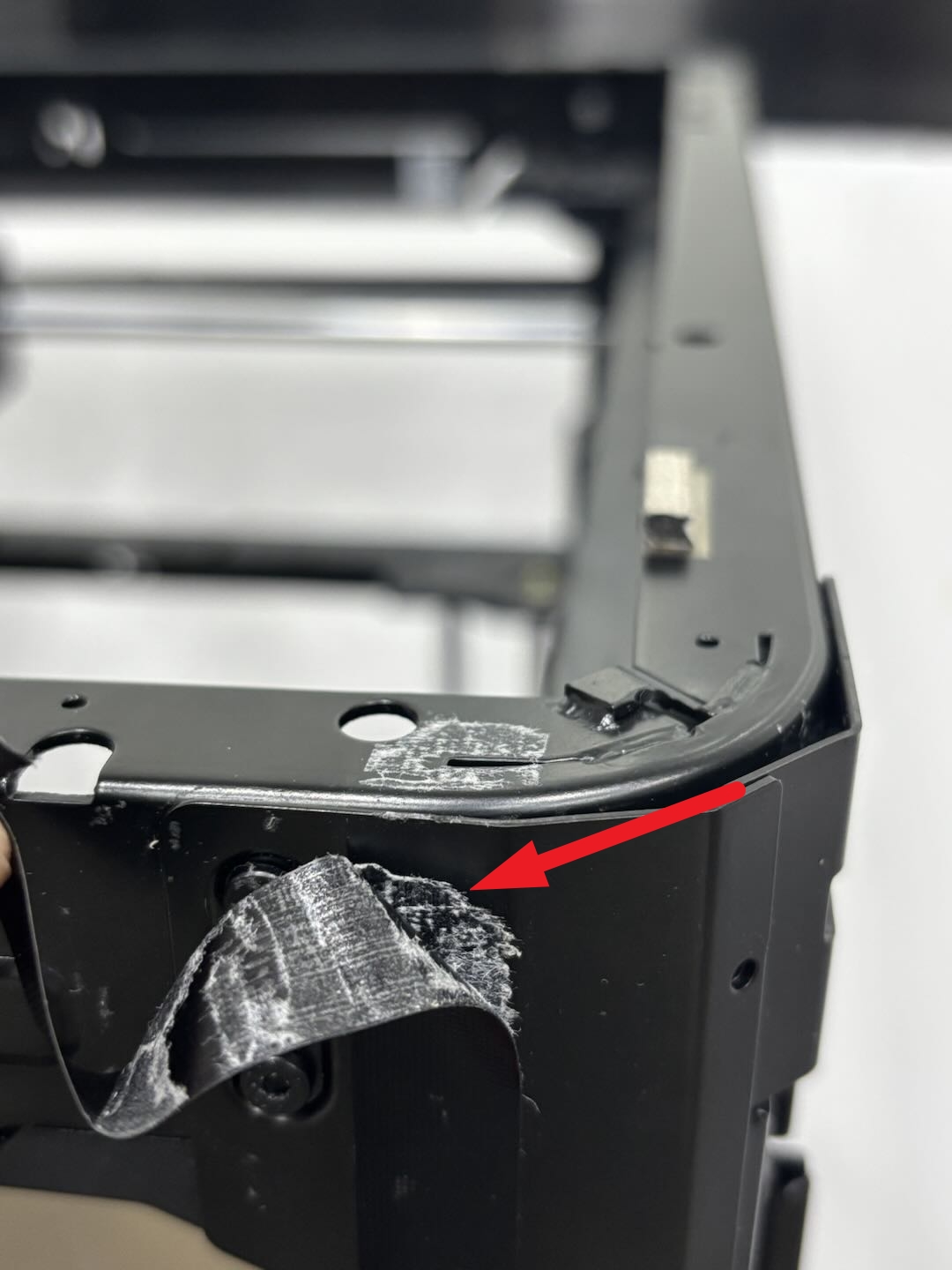
Since the Wifi antenna needs to pass through the small hole in the beam, you can first remove the 4 fixing screws of the AP board, pull the AP board out of the beam and disconnect the Wifi antenna cable.
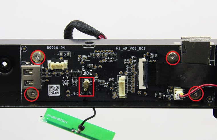
Then, remove the screws securing the front cover and take out the Wifi antenna along with the front cover.
 |
 |
 |
Note: There is no need to separate the Wifi antenna from the front cover, the Wifi antenna can be removed together with the front cover.
You can refer to the following Wiki for detailed steps on how to replace the front cover and screen of the P1P/P1S:
¶ Step 2:Remove left/right panels, rear panel and glass front door
Since the P1P does not have left/right side panels or a glass front door, if your P1P has not had the P1P Enclosure Kit installed, you only need to refer to the subsequent steps for replacing the rear panel.
- Remove the P1S front glass door
You can use an H2.0 Allen key to remove the 4 front glass door screws:
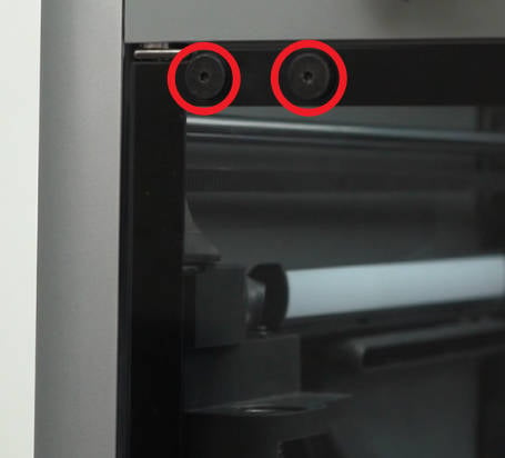 |
 |
You can refer to the following wiki for detailed steps on how to replace the front glass door of P1S: Replace the Front Glass Door
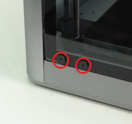
- Remove the P1P/P1S rear panel
You can refer to the following wiki for detailed steps on how to replace the rear panel of P1P/P1S:
- Remove the P1S right panel
You can refer to the following wiki for detailed steps on how to replace the right panel of P1S: Replace the Right Plastic Panel
- Remove the P1S left panel
You can refer to the following wiki for detailed steps on how to replace the left panel of P1S: Replace the Left Plastic Panel
¶ Step 3: Remove the TH board/extruder/hotend
- Remove the hotend and extruder
You can remove the hotend and extruder together. Press down on the pneumatic connector to remove the PTFE tube and disconnect the cable from the extruder interface board. Use an H1.5 Allen key to loosen the cutter fixing screw so that the cutter can naturally hang down, then use an H2.0 Allen key to remove the three screws securing the extruder.
 |
 |
 |
You can refer to the following wiki for detailed steps on how to replace the hotend and extruder of P1P/P1S:
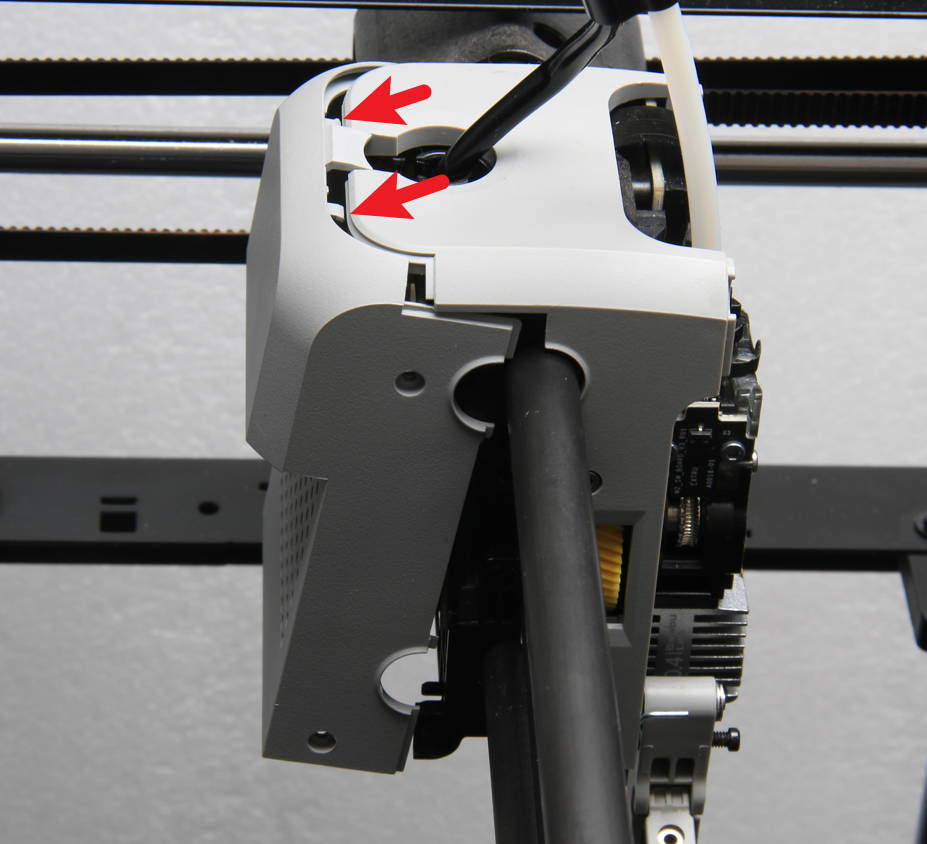
- Remove the Toolhead Middle Cover and Rear Cover
Use an H1.5 Allen key to remove the eight screws from the toolhead rear cover and middle cover.
 |
 |
Separate the toolhead rear cover from the middle cover and remove the rear cover. Then, remove the middle cover, being careful not to get scratched by the cutter.
 |
 |
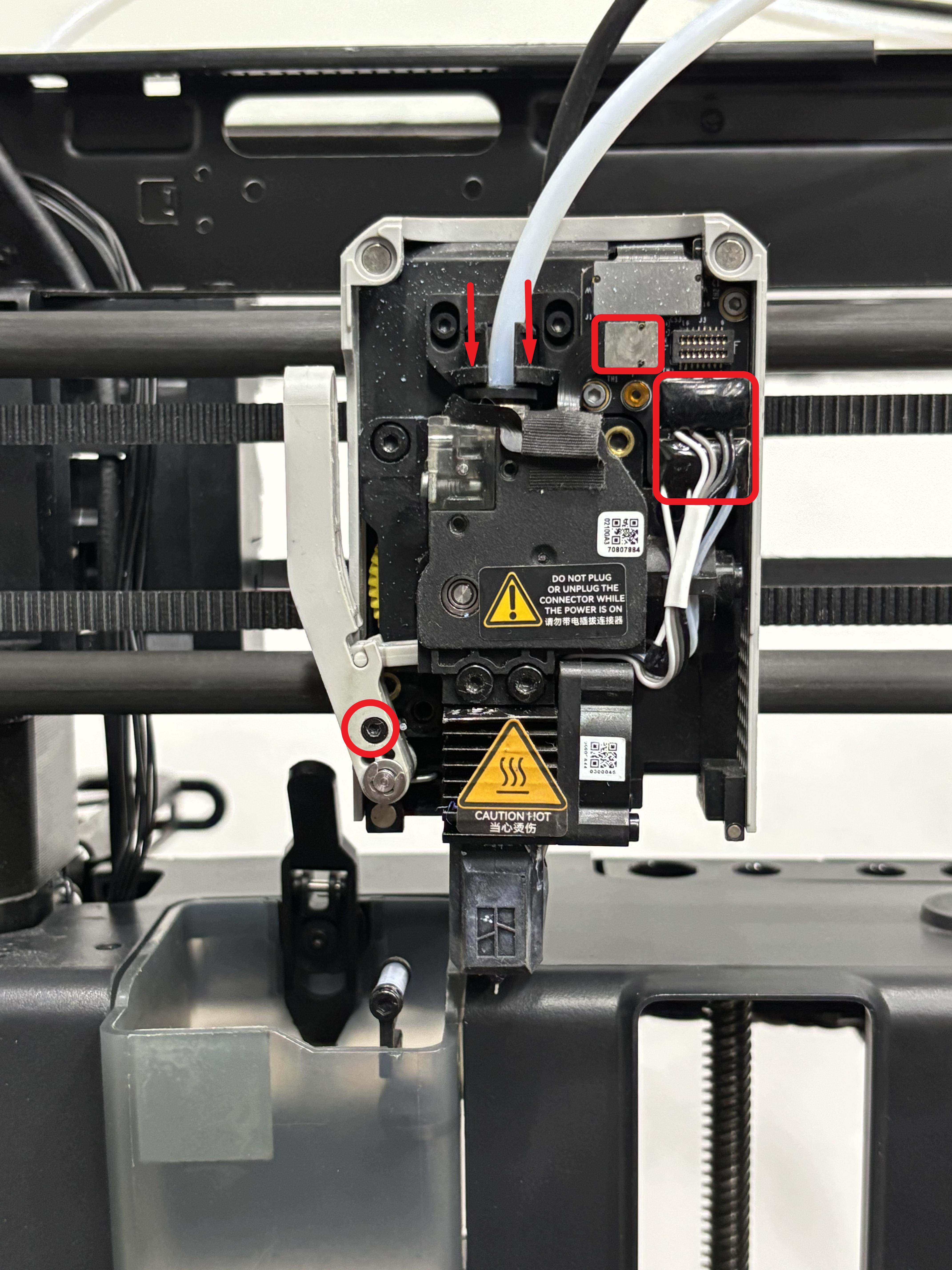
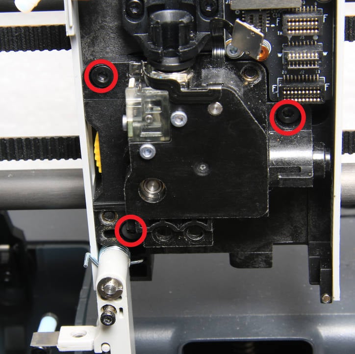
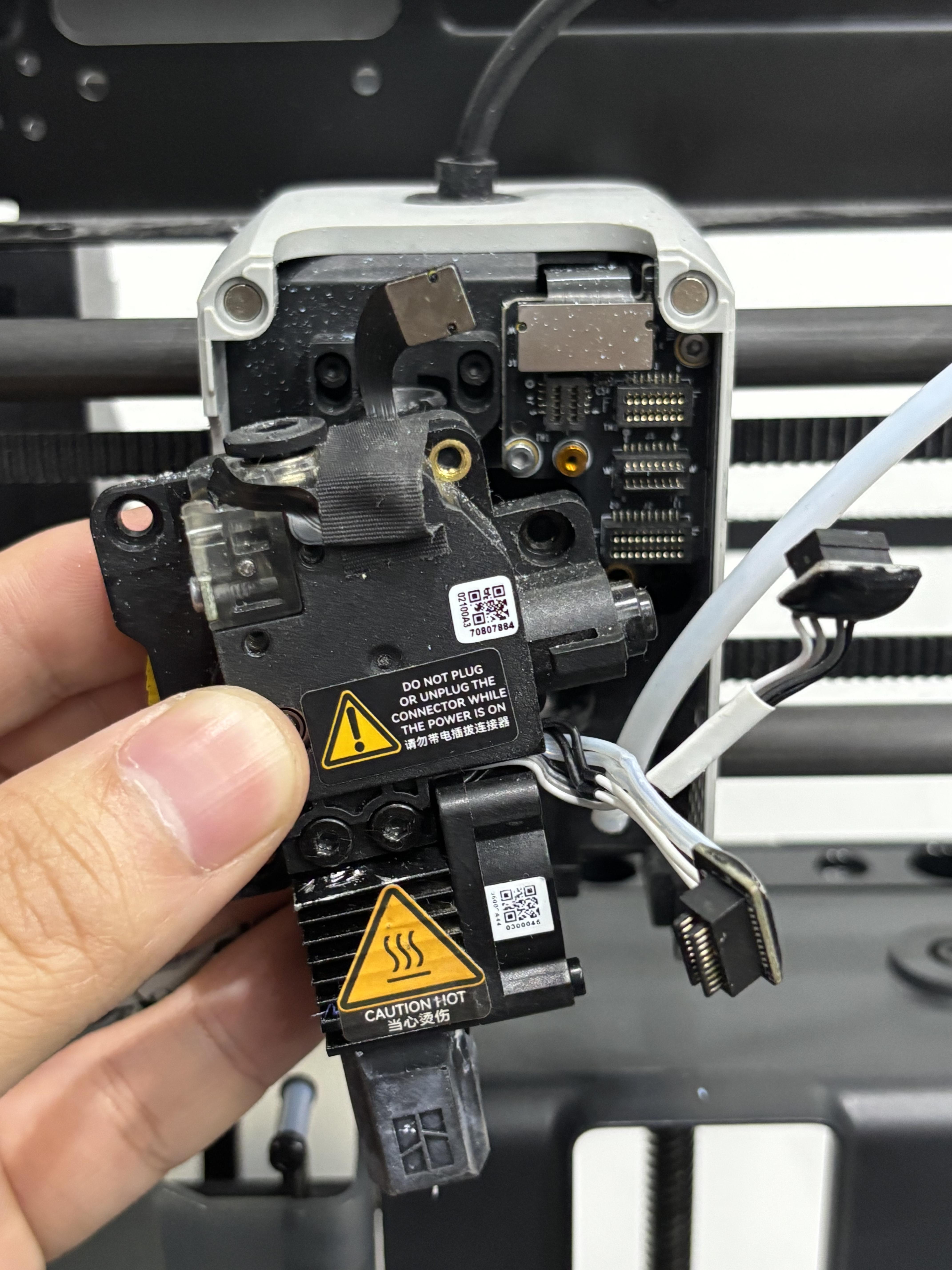
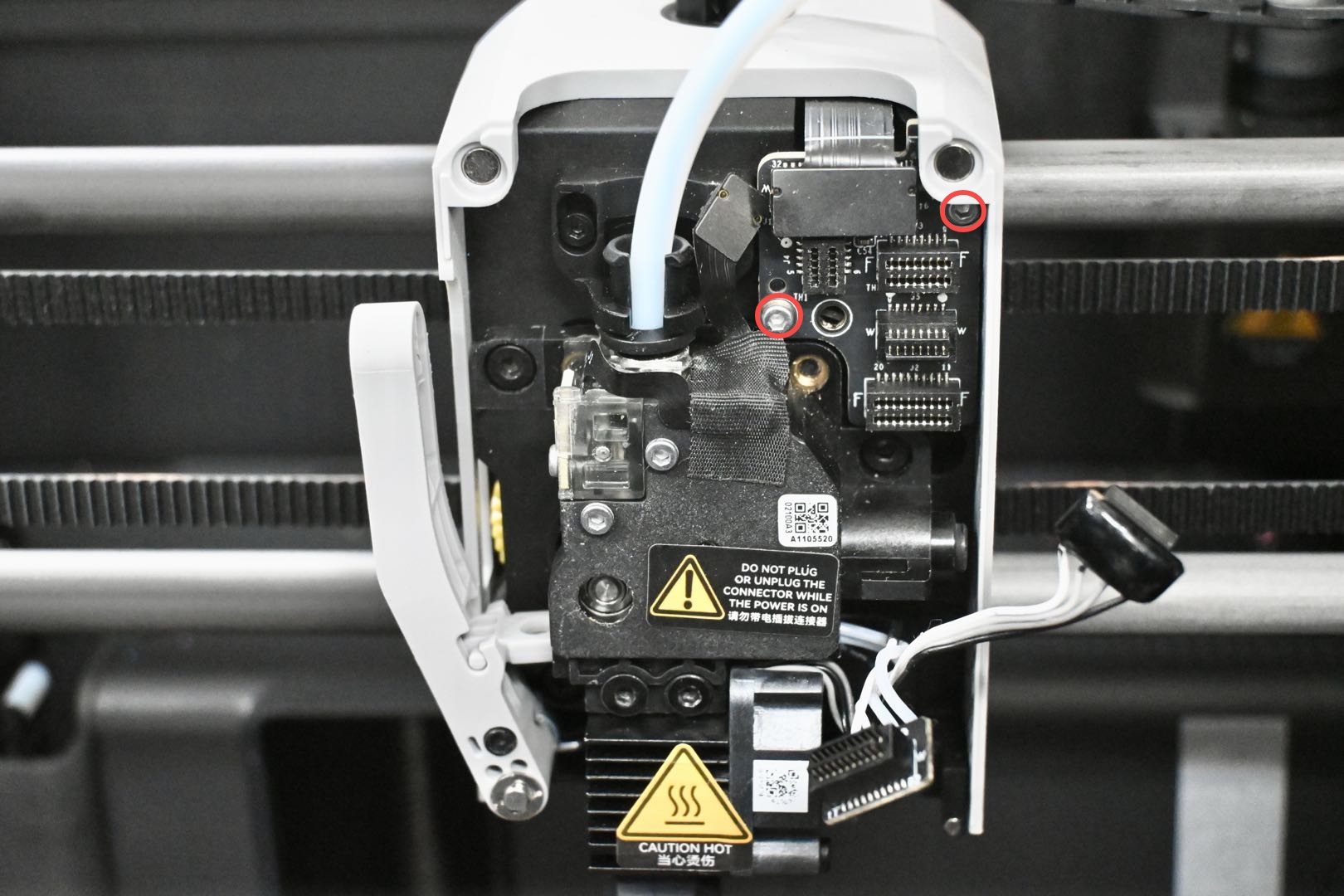
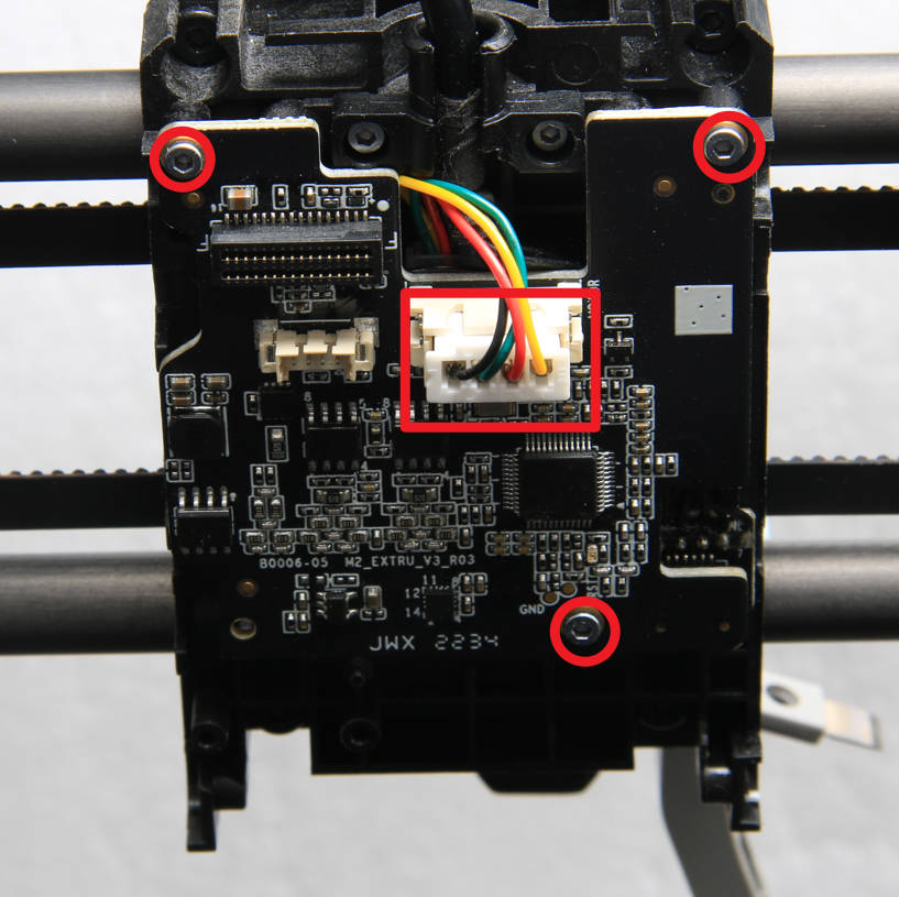
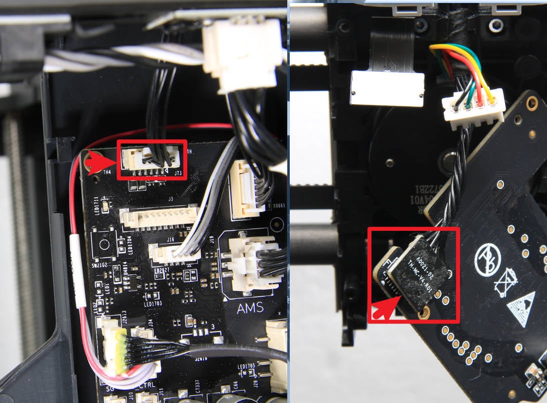
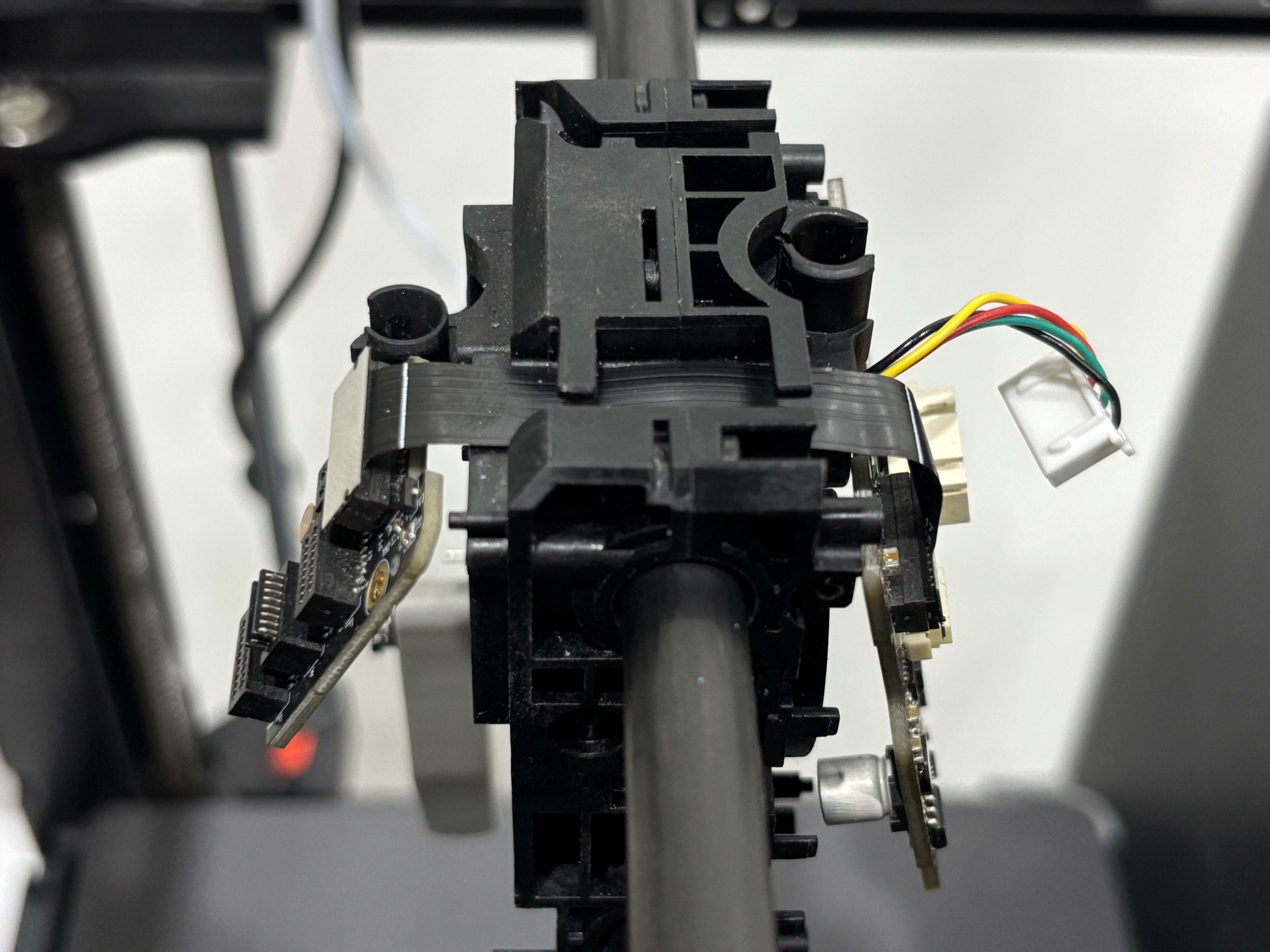
- Remove the TH board assembly
For easier reinstallation, there is no need to disconnect the TH board/extruder connection board from the FPC cable; they can be removed together from the toolhead.
Use an H1.5 Allen key to remove the two screws securing the extruder connection board. Disconnect the extruder motor cable, then use an H1.5 Allen key to remove the three screws securing the TH board. Flip the TH board over and disconnect the toolhead cable from the other side of the TH board. Finally, remove the TH board assembly from the toolhead.
 |
 |
 |
 |
You can refer to the following Wiki to remove the parts from the P1P/P1S toolhead: Toolhead Board Replacement Guide
¶ Step 4: Remove the AP board/screen/cables
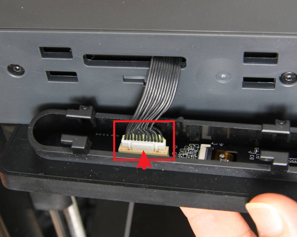
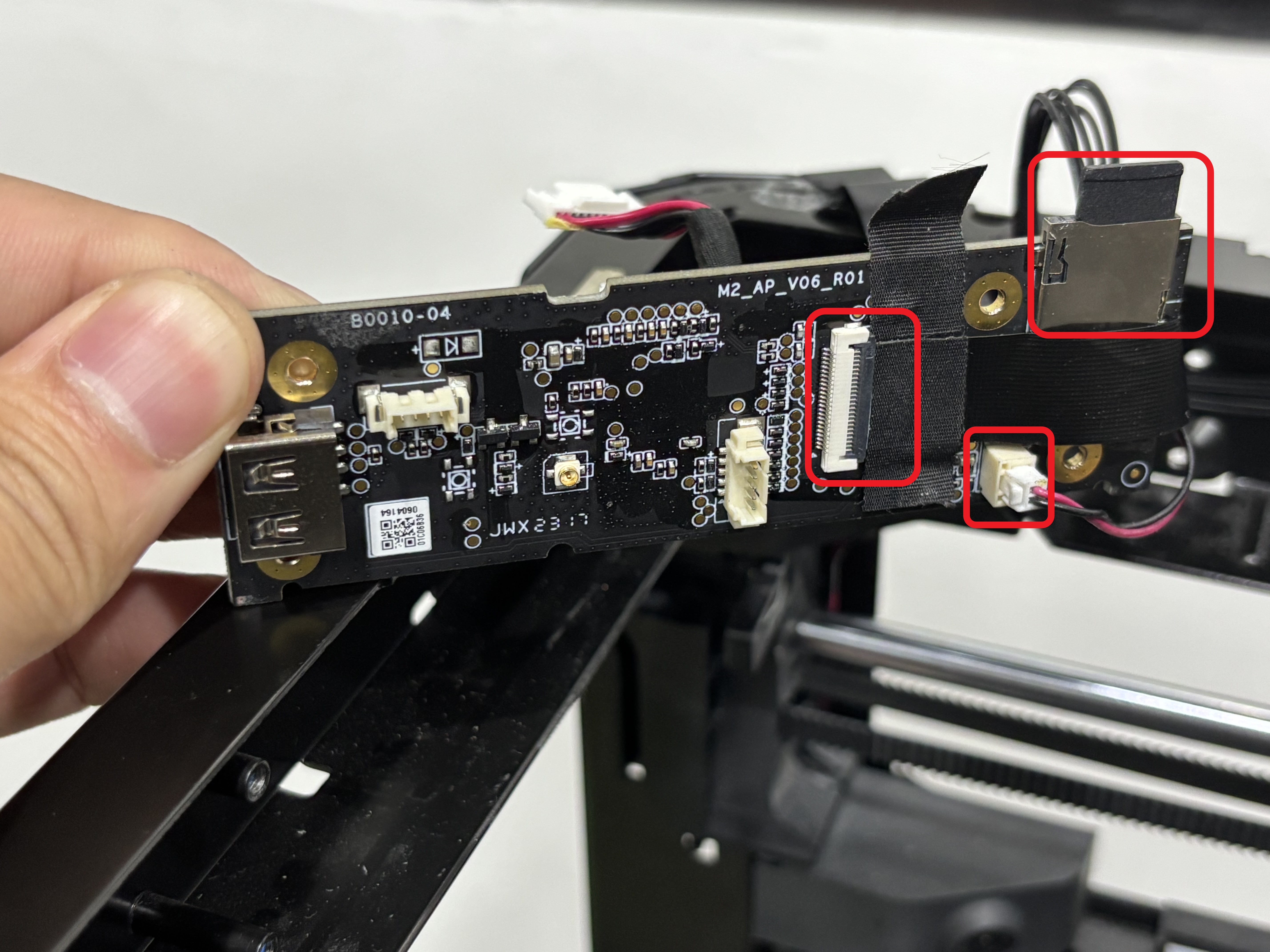
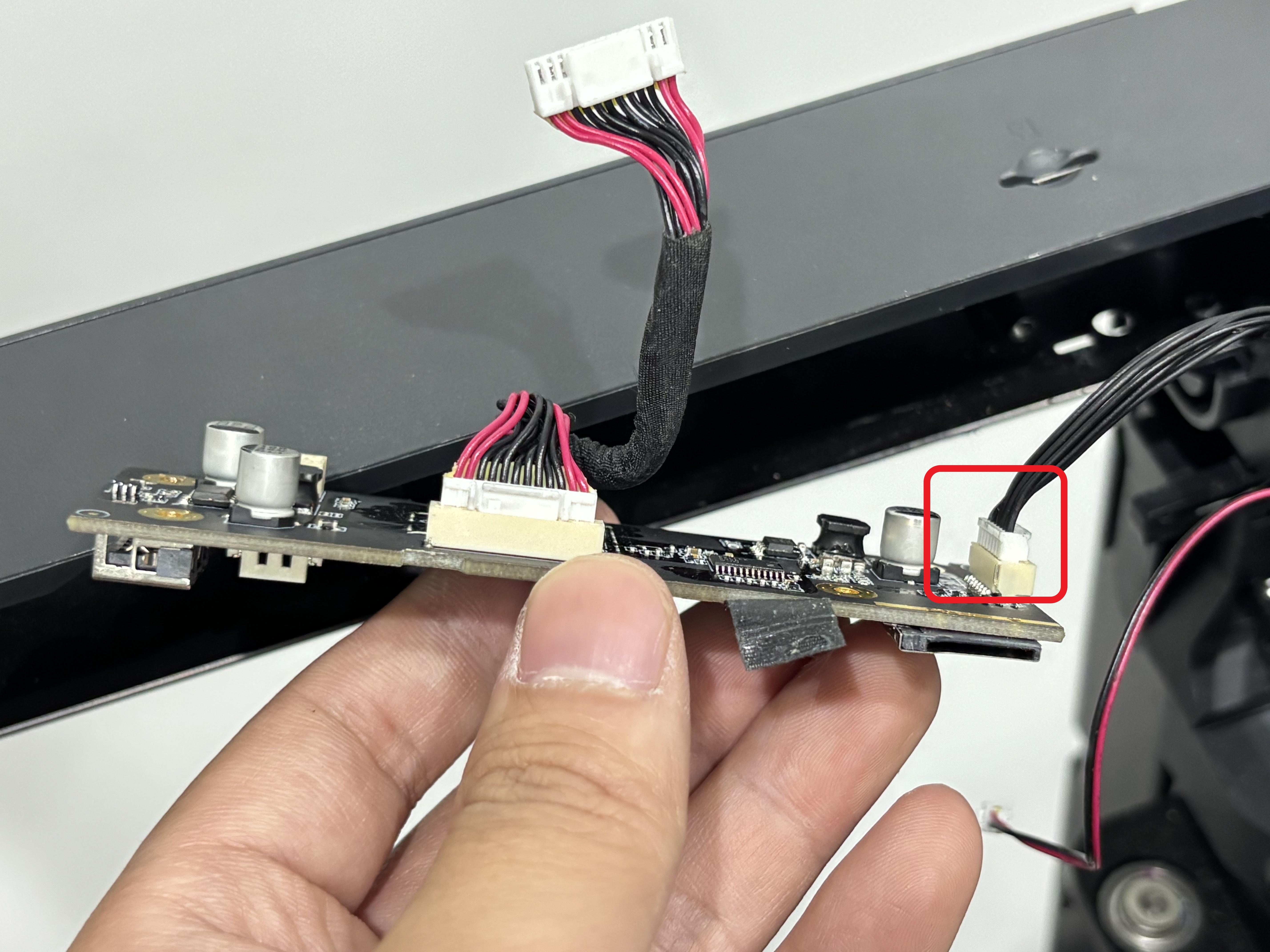
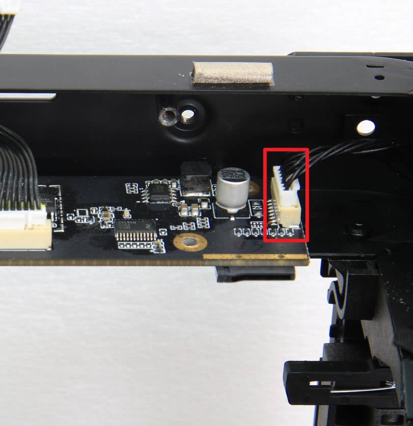
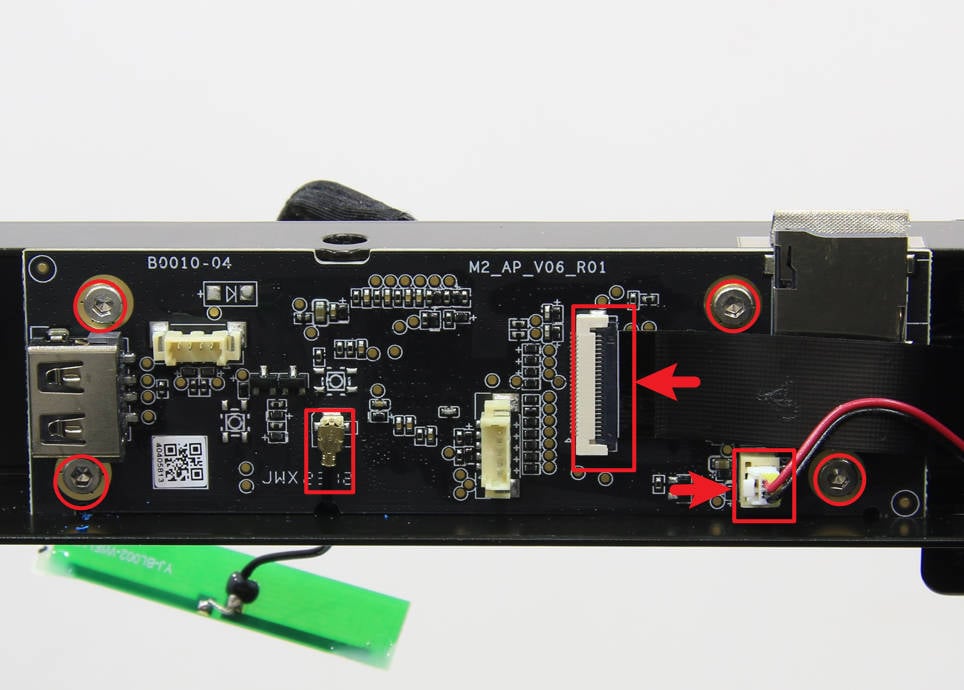
- Remove the AP board
Disconnect the MC-AP cable, LED light cable, and camera cable. At the same time, remove the SD card and then remove the AP board.
Note: The AP board's securing screws were already removed when removing the front cover.
 |
 |
You can refer to the following Wiki for detailed steps on how to replace the AP board of P1P/P1S: Replace the AP Board for P1 Series
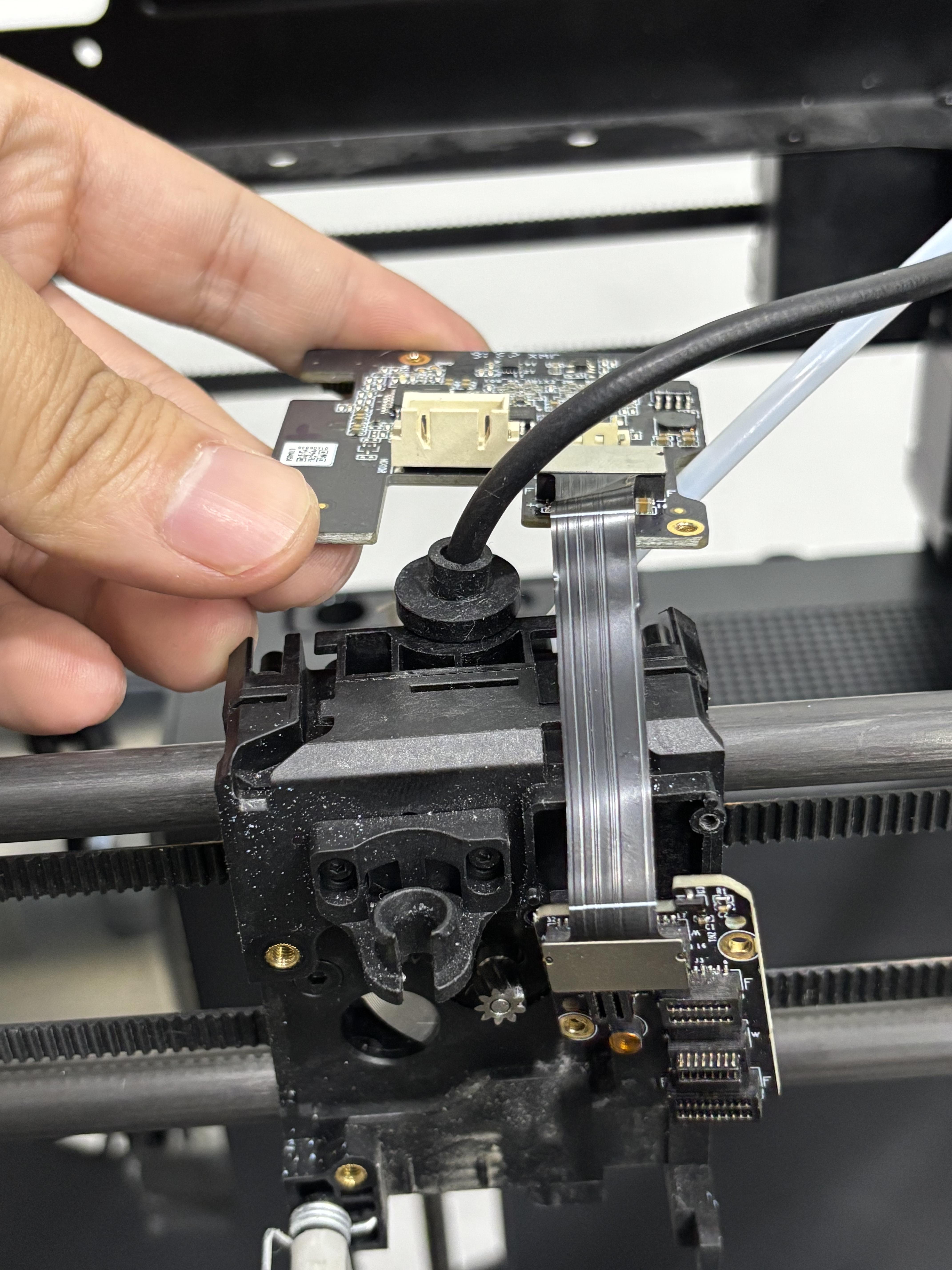
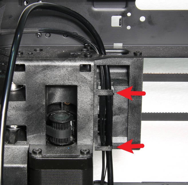
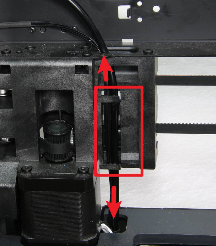
- Remove MC-AP cable
Since the MC-AP cable was disconnected from the AP board during the AP board removal process, you only need to detach the MC-AP cable from the core XY movement system. You can peel off the securing tape, loosen the cable from the cable channel, and then remove the MC-AP cable.
Note: You do not need to disconnect the MC-AP cable from the MC board. You can simply pull the cable out of the cable channel.
 |
 |
You can refer to the following Wiki for detailed steps on how to replace the MC-AP cable of P1P/P1S: MC-AP cable
- Remove the toolhead cable
Since the toolhead cable was disconnected from the TH board during the TH board removal process, you can disconnect the toolhead cable from the MC board and then remove the toolhead cable.
Note: Since there is a silicone sleeve on the end of the toolhead cable connected to the TH board, this end cannot be removed from the cable channel. Therefore, you need to disconnect it from the MC board and then remove the toolhead cable from the cable channel.
 |
 |
You can refer to the following Wiki for detailed steps on how to replace the toolhead cable of P1P/P1S: Toolhead cable
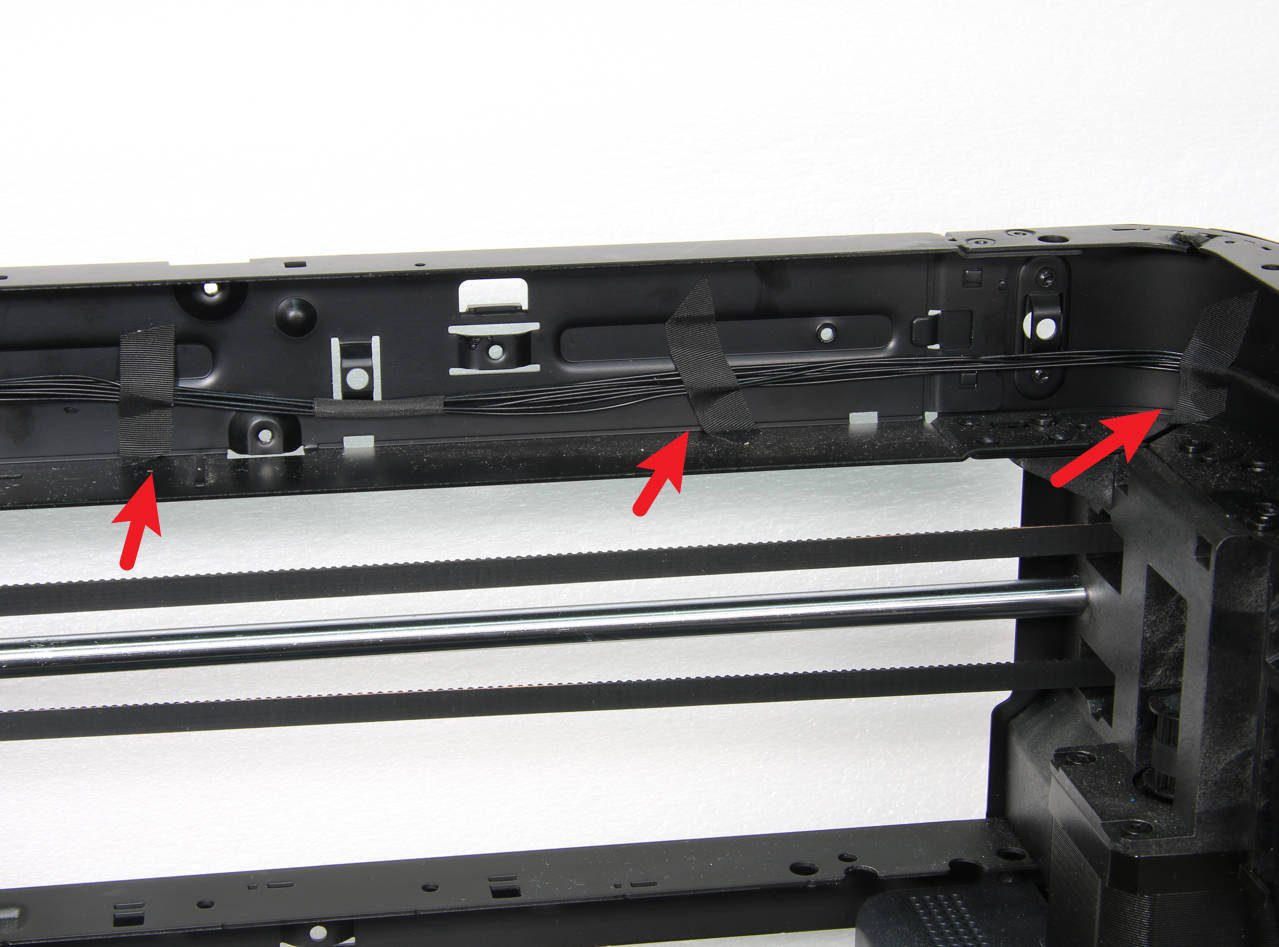
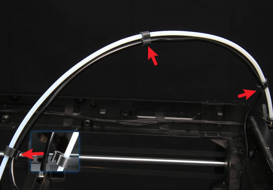
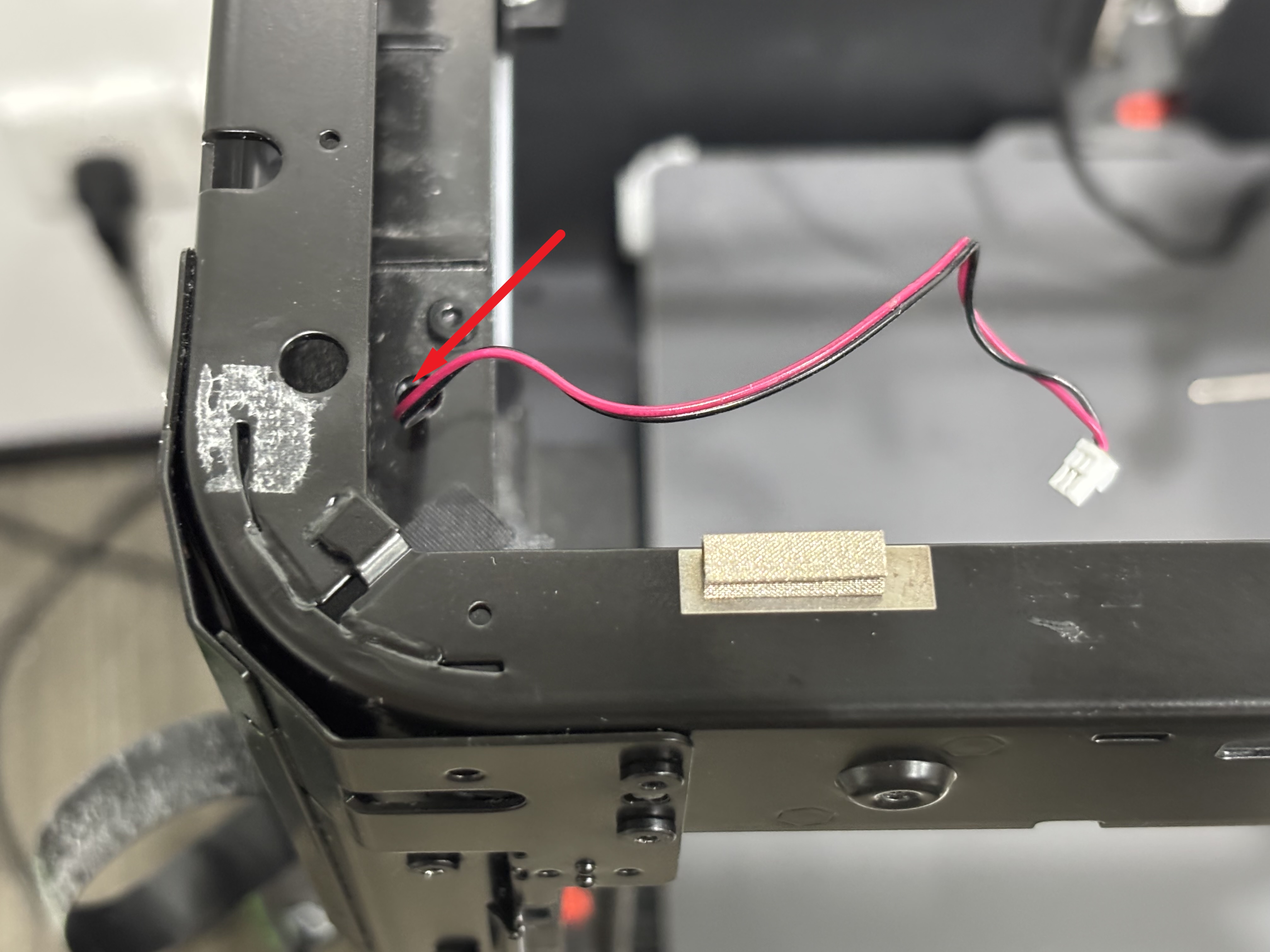
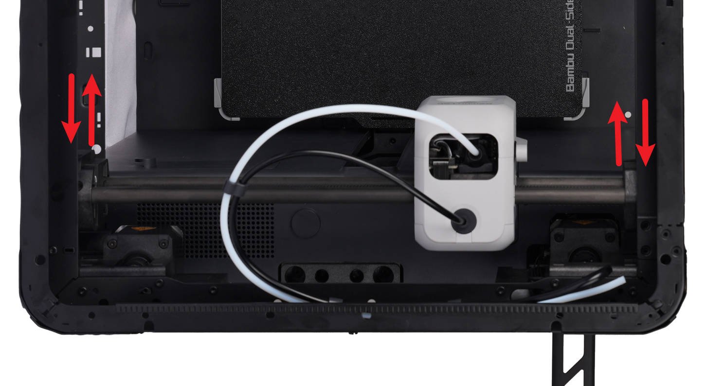
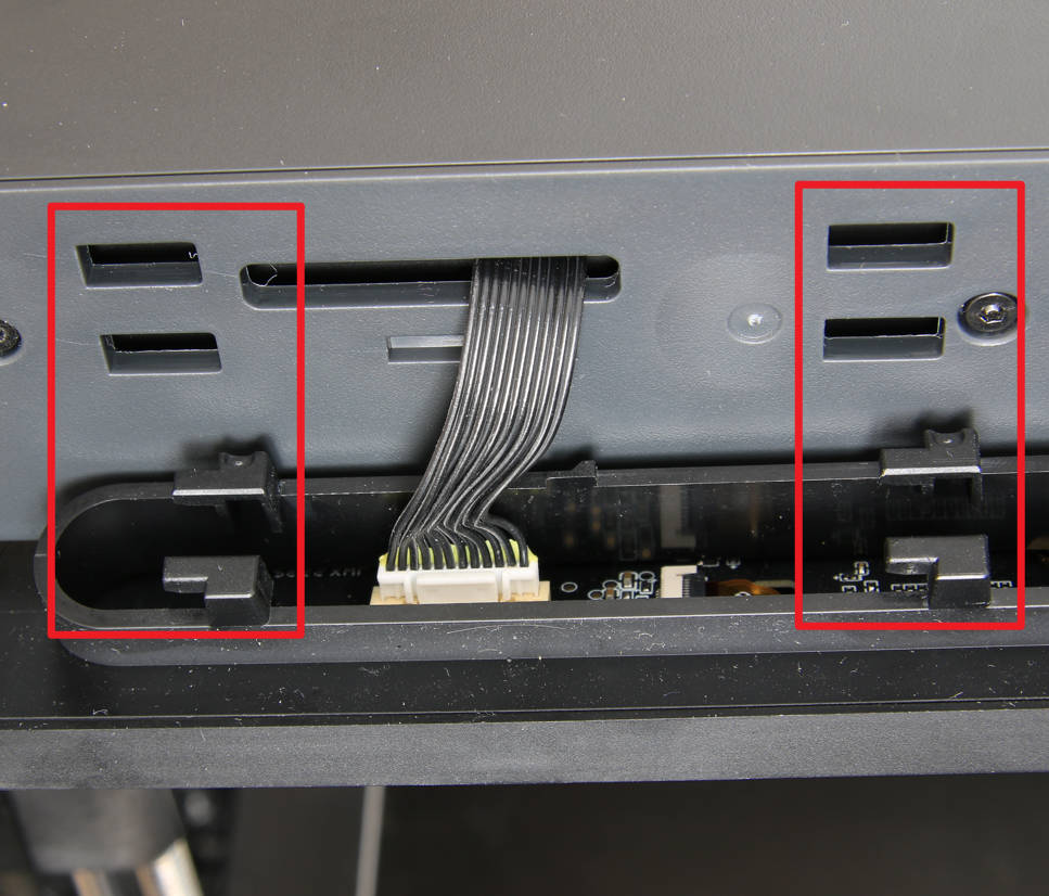
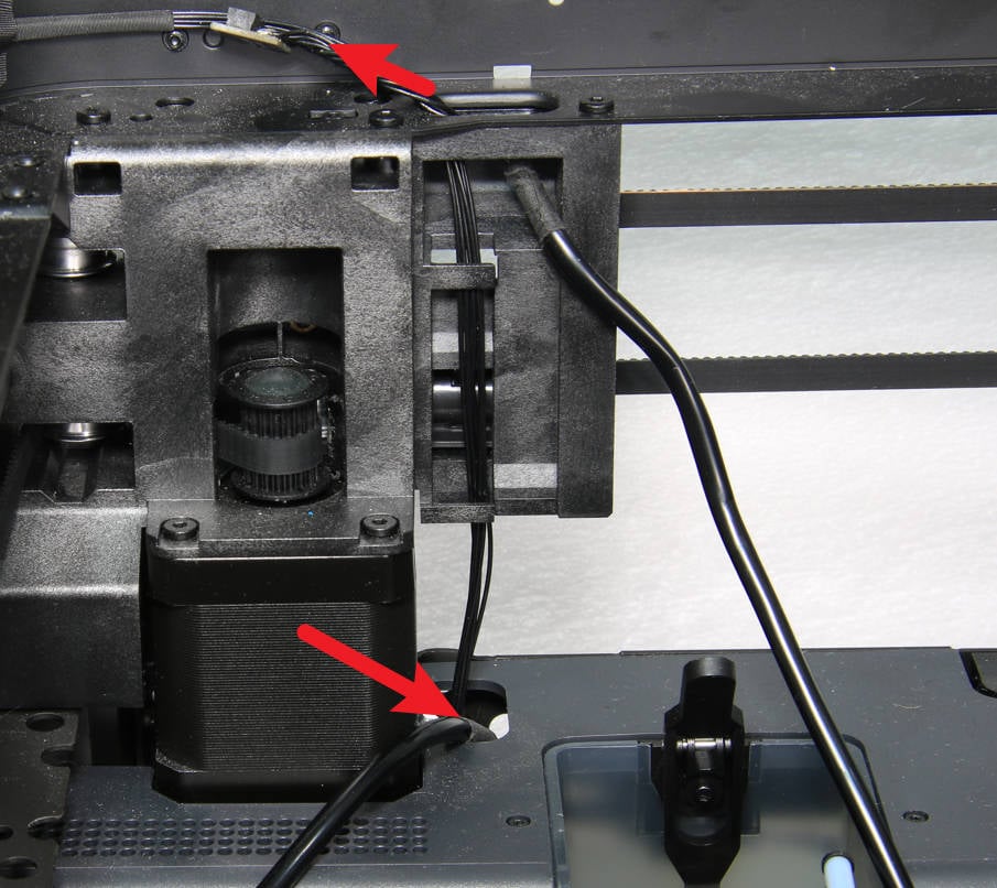
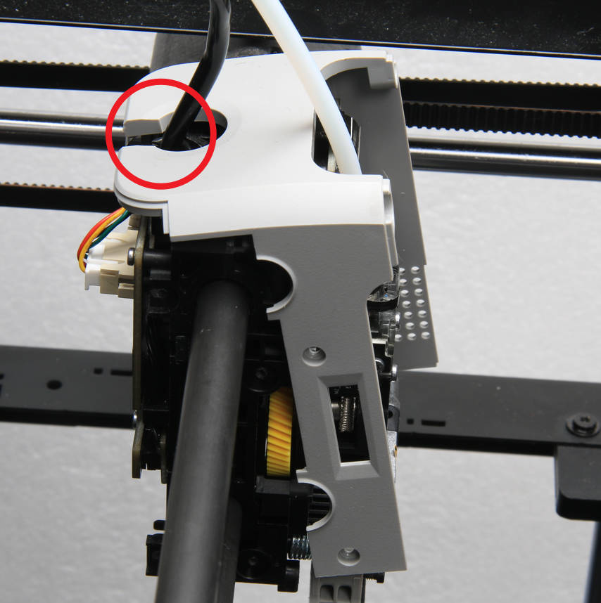
- Remove the LED Light Cable and Camera Cable
Pull the LED light cable out from the small hole in the X/Y frame, then peel off the camera cable.
 |
 |
- Remove the cable chain
If there is no cable chain, this step can be ignored.
You can refer to the following Wiki for detailed steps on how to replace the cable chain of P1P/P1S: Replace the Cable Chain Assembly
¶ Step 5: Remove the XY tensioner/motor
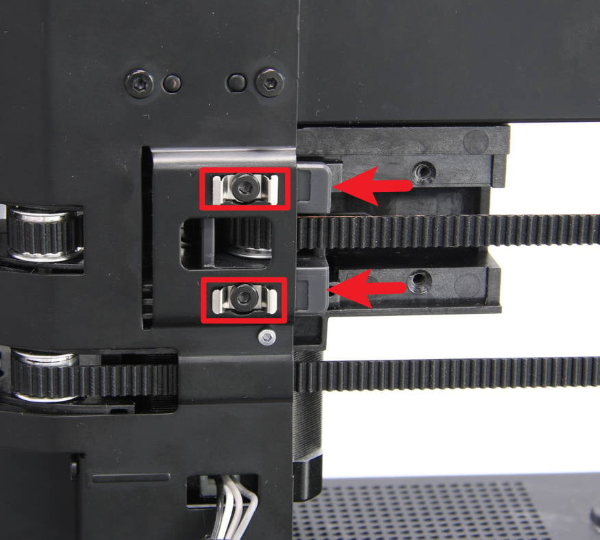
- Remove the XY tensioner
Use an H2.0 Allen key to remove the 2 screws and remove the tensioner holder and spring.
 |
 |
Then use an H2.0 Allen key to remove the 2 screws and the limit holder to loosen the tensioner.
 |
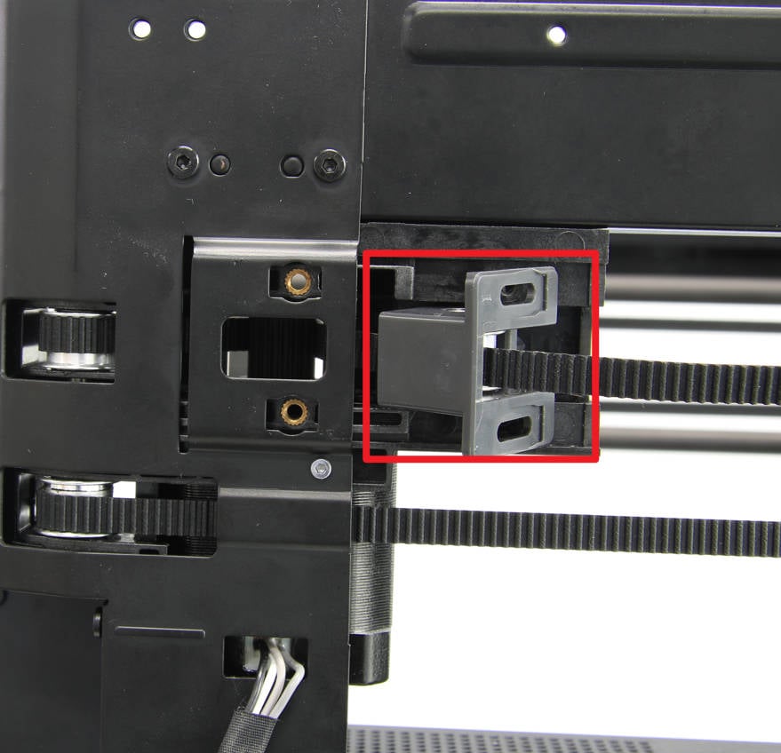 |
- Remove the XY motor
For easier reinstallation, only the X/Y motors need to be removed from the printer. You can place the motors on the lining without disconnecting the motor cables from the MC board.
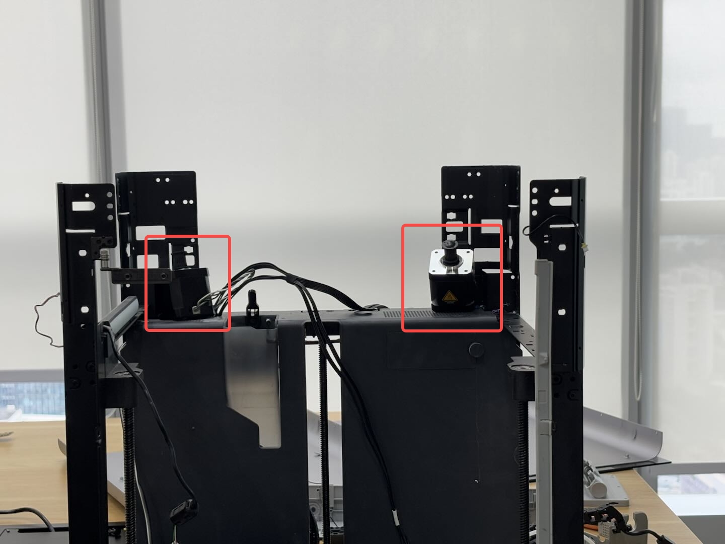
You can refer to the following wiki for detailed steps to replace the XY motor of P1P/P1S. Both motors mounted on the core XY movement system need to be removed: XY motor
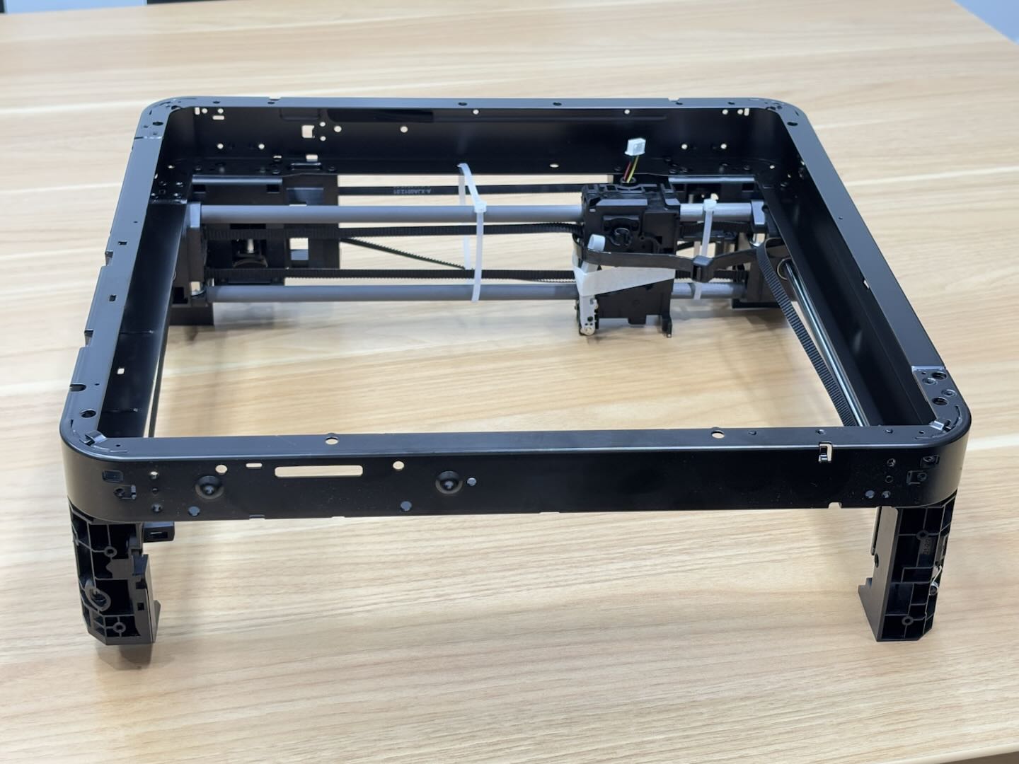
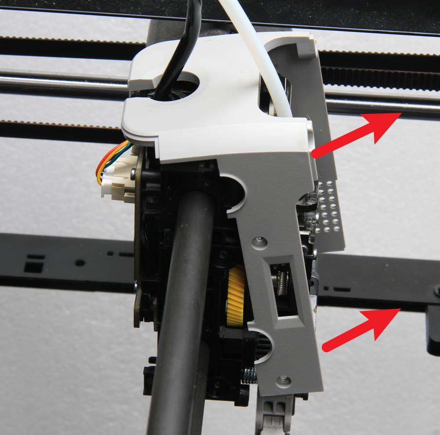
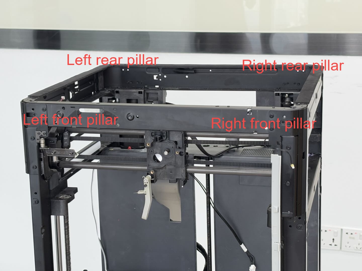
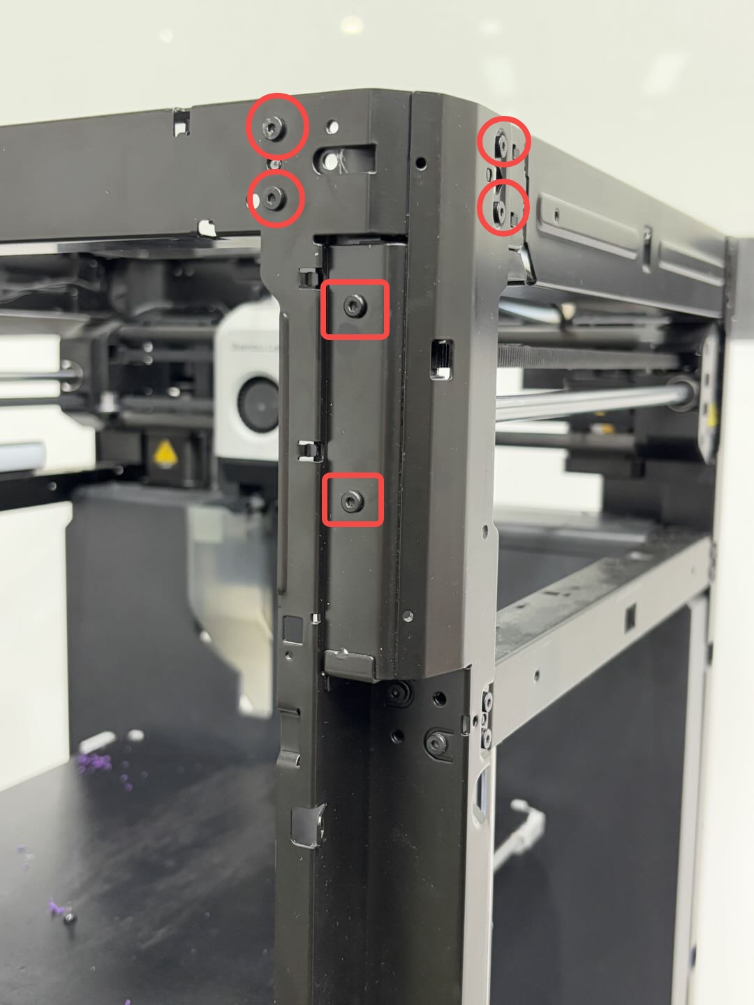
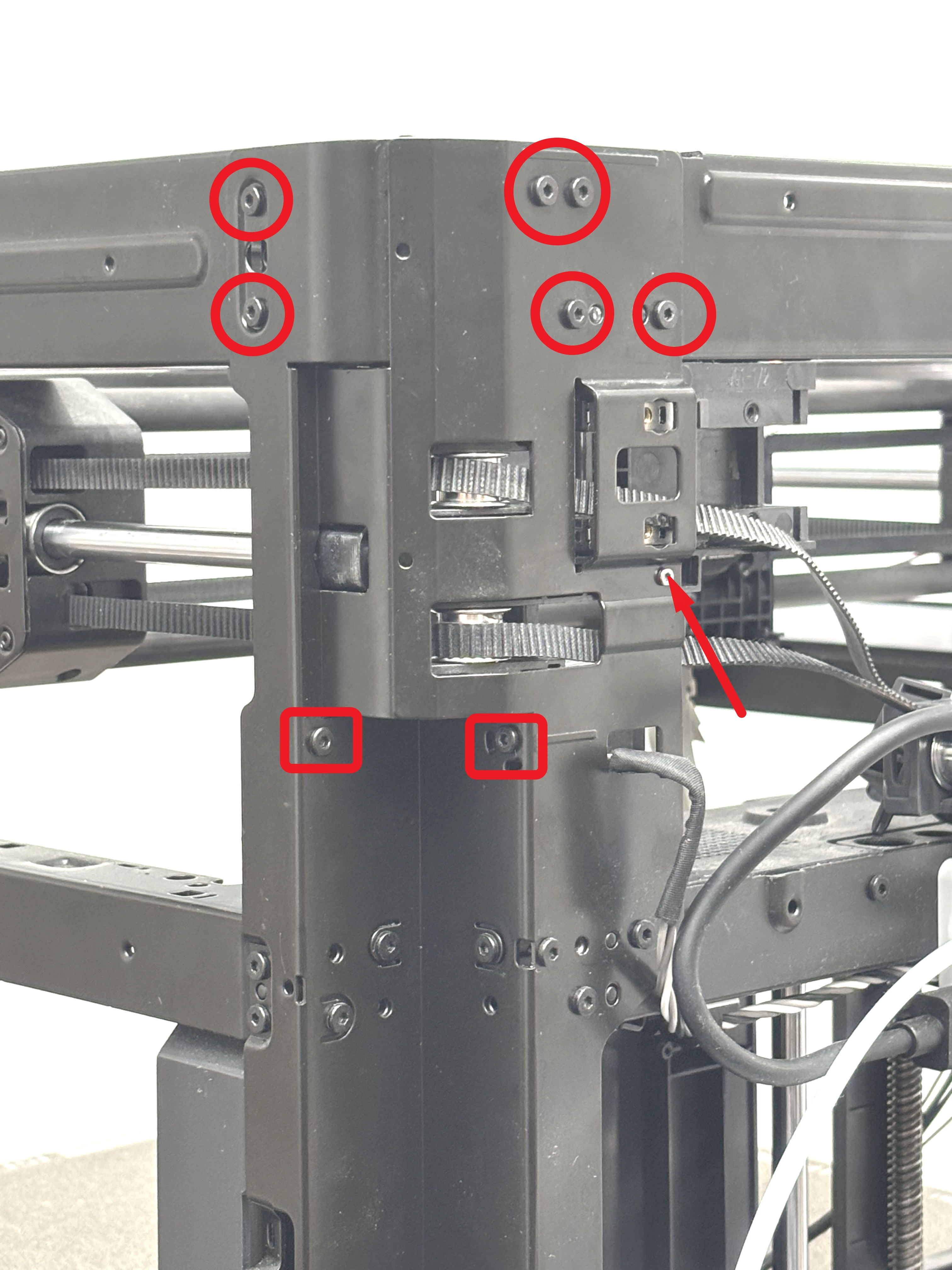
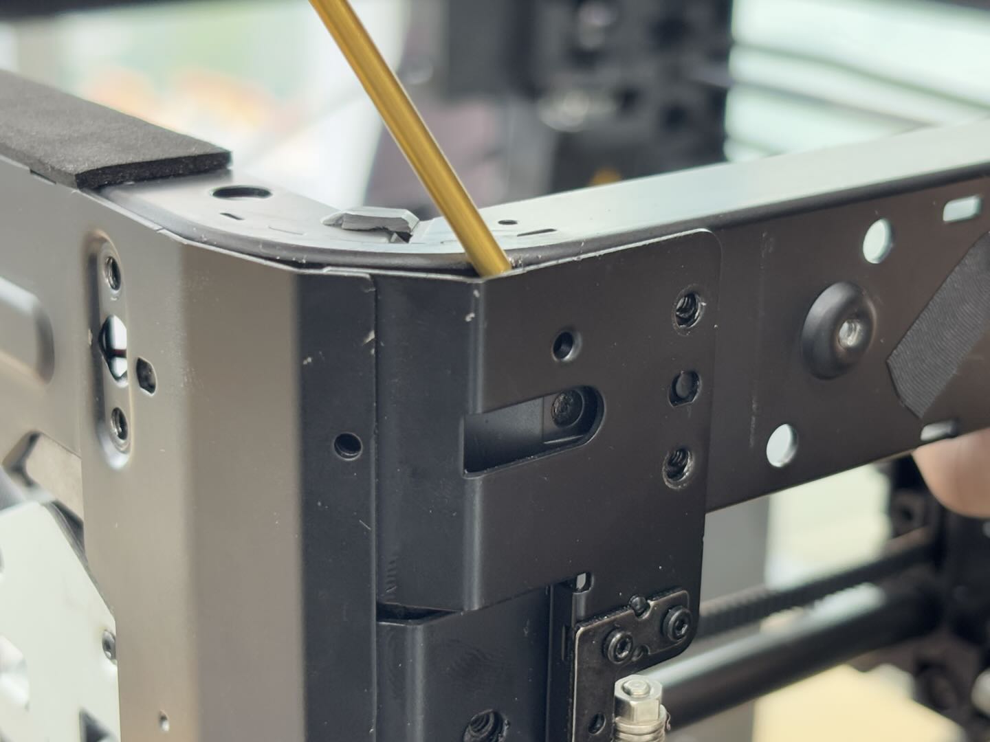
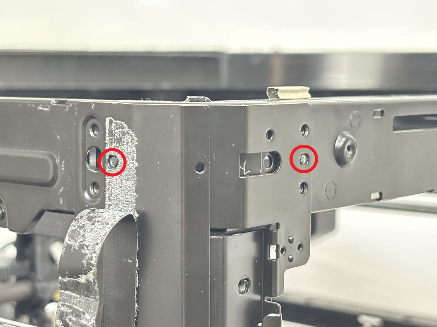
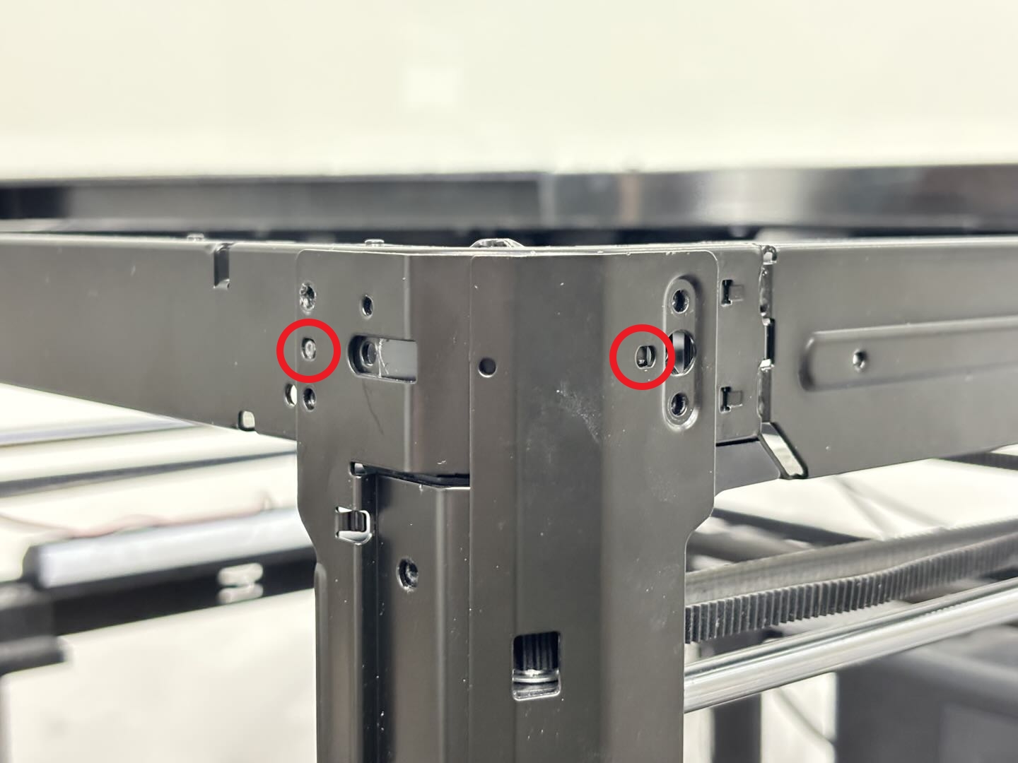
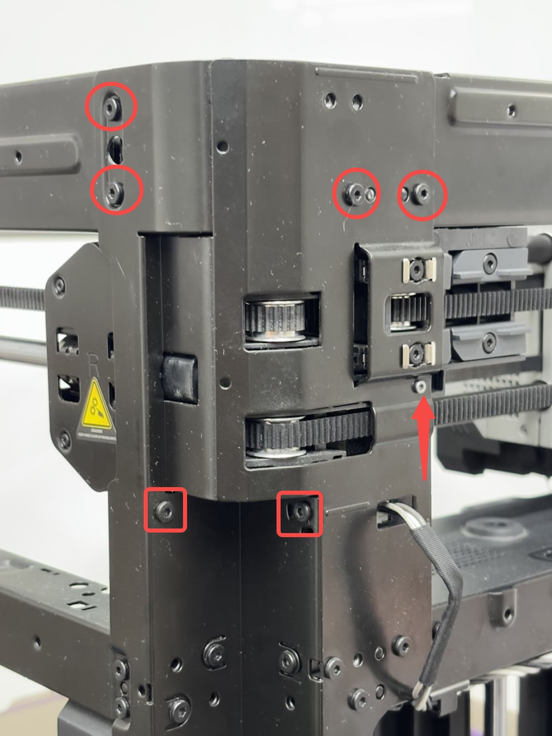
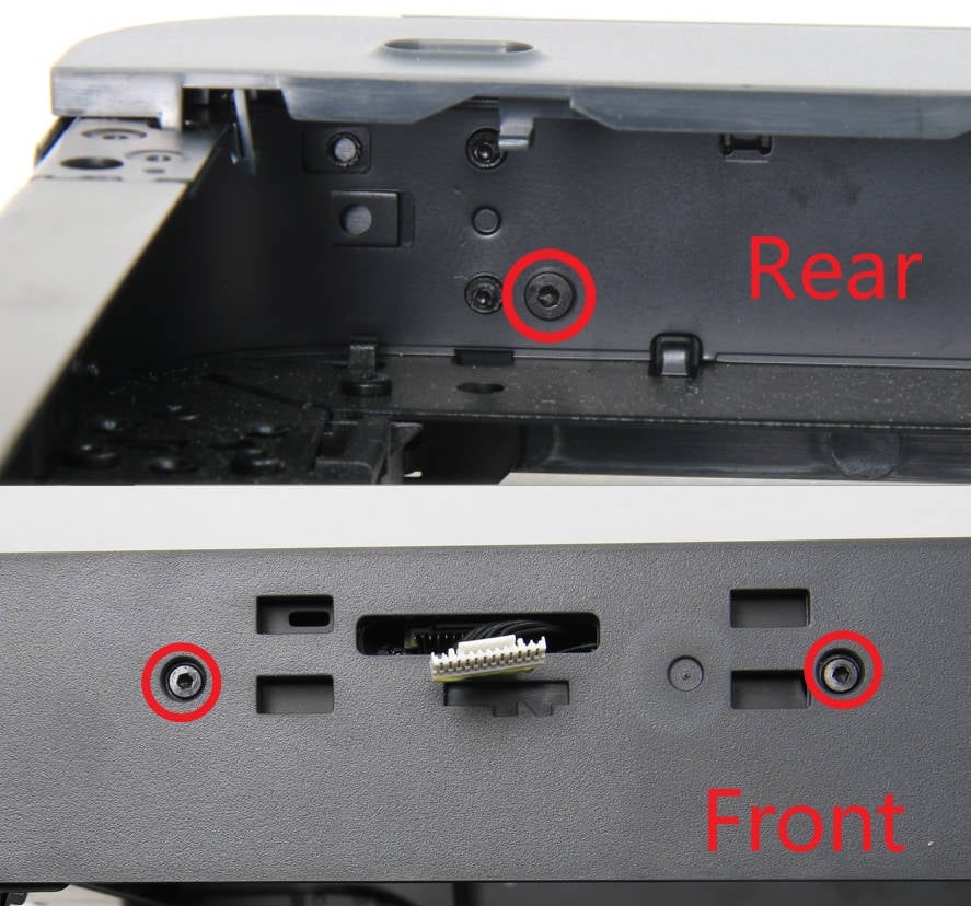
¶ Step 6: Remove the core XY movement system
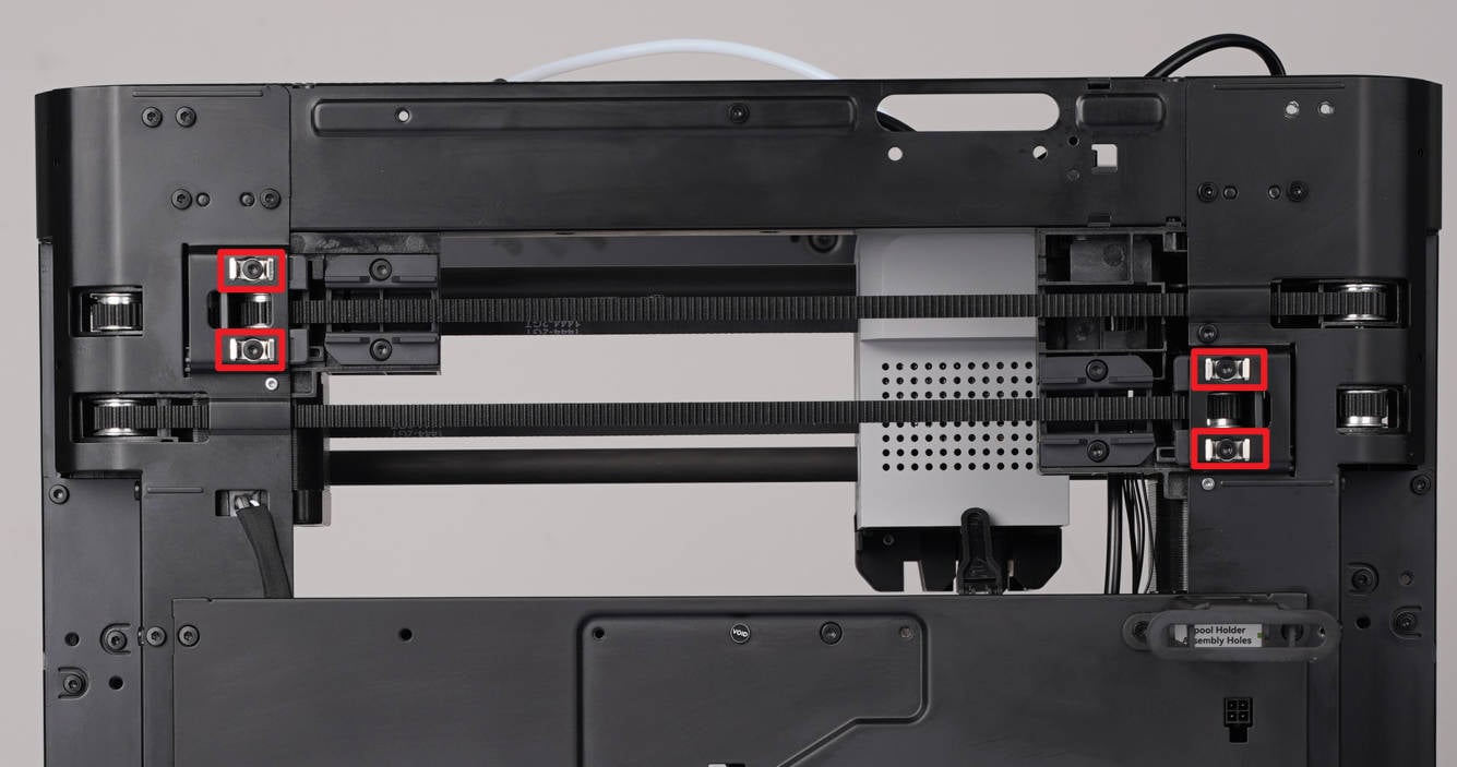
Remove the screws:
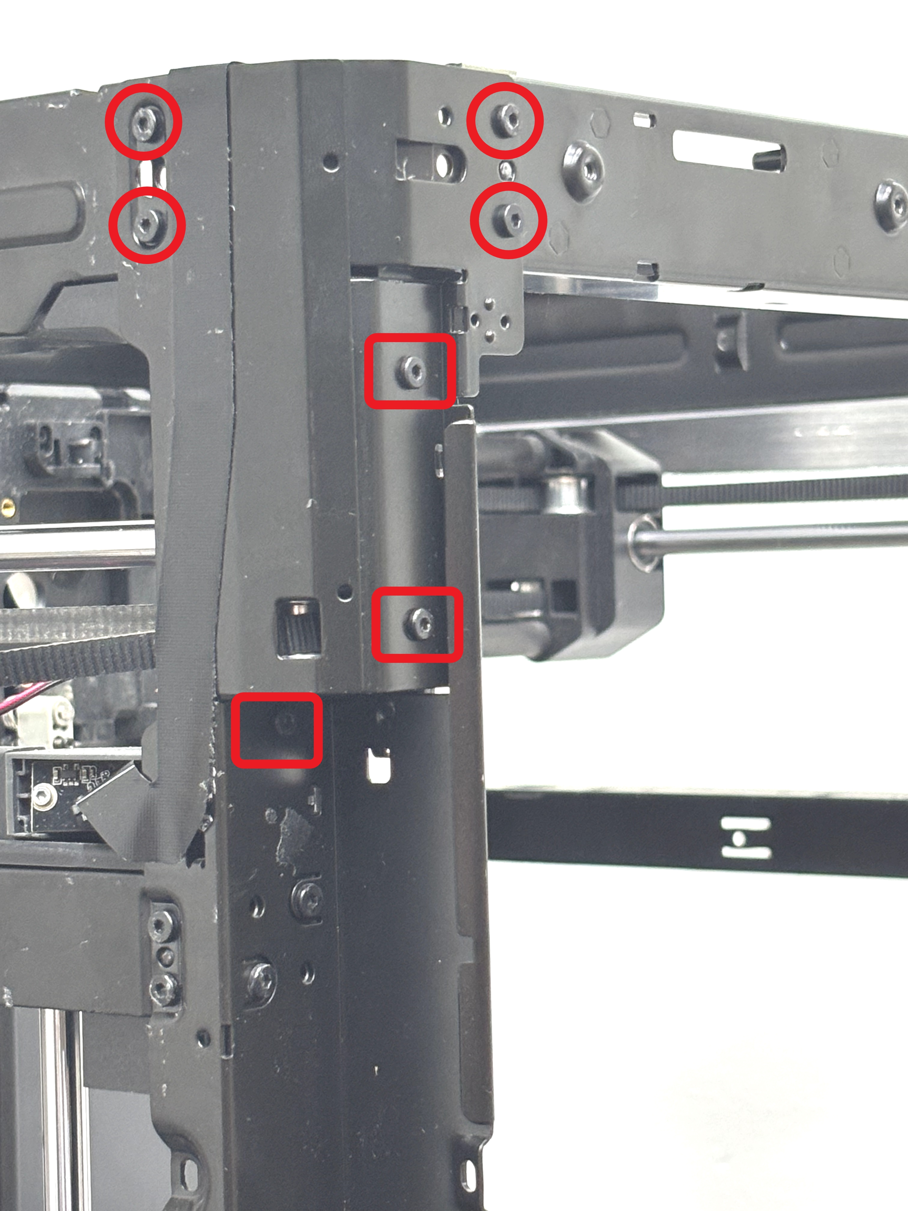
The core XY movement system uses 3 different screws to fix the 4 pillars. The screws marked with circles are all of the same specification, and the screws marked with squares are also of the same specification. The 4 pillars are left front, right front, left rear, and right rear.
- Remove the screws of the left front pillar:
Use an H2.0 Allen key to remove the 4 circled screws, and then use an H2.0 Allen key to remove the 3 squared screws.
- Remove the screws of the right front pillar:
Use an H2.0 Allen key to remove the 4 circled screws, and then use an H2.0 Allen key to remove the 2 squared screws.
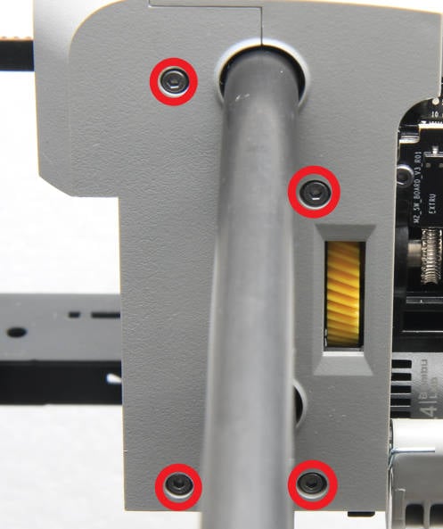
- Remove the screws of the left rear pillar:
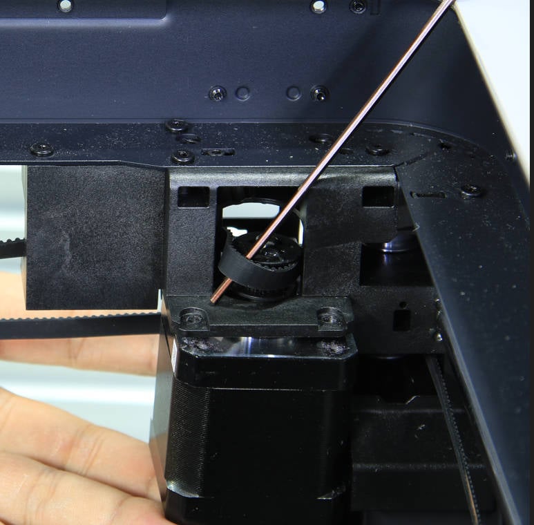
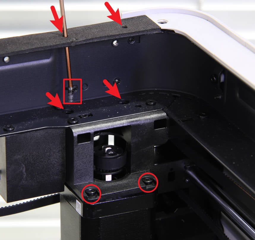
Use an H2.0 Allen key to remove the 4 circled screws, then use an H2.0 Allen key to remove the 3 squared screws, and use an H1.5 Allen key to remove 1 silver screw marked with an arrow.
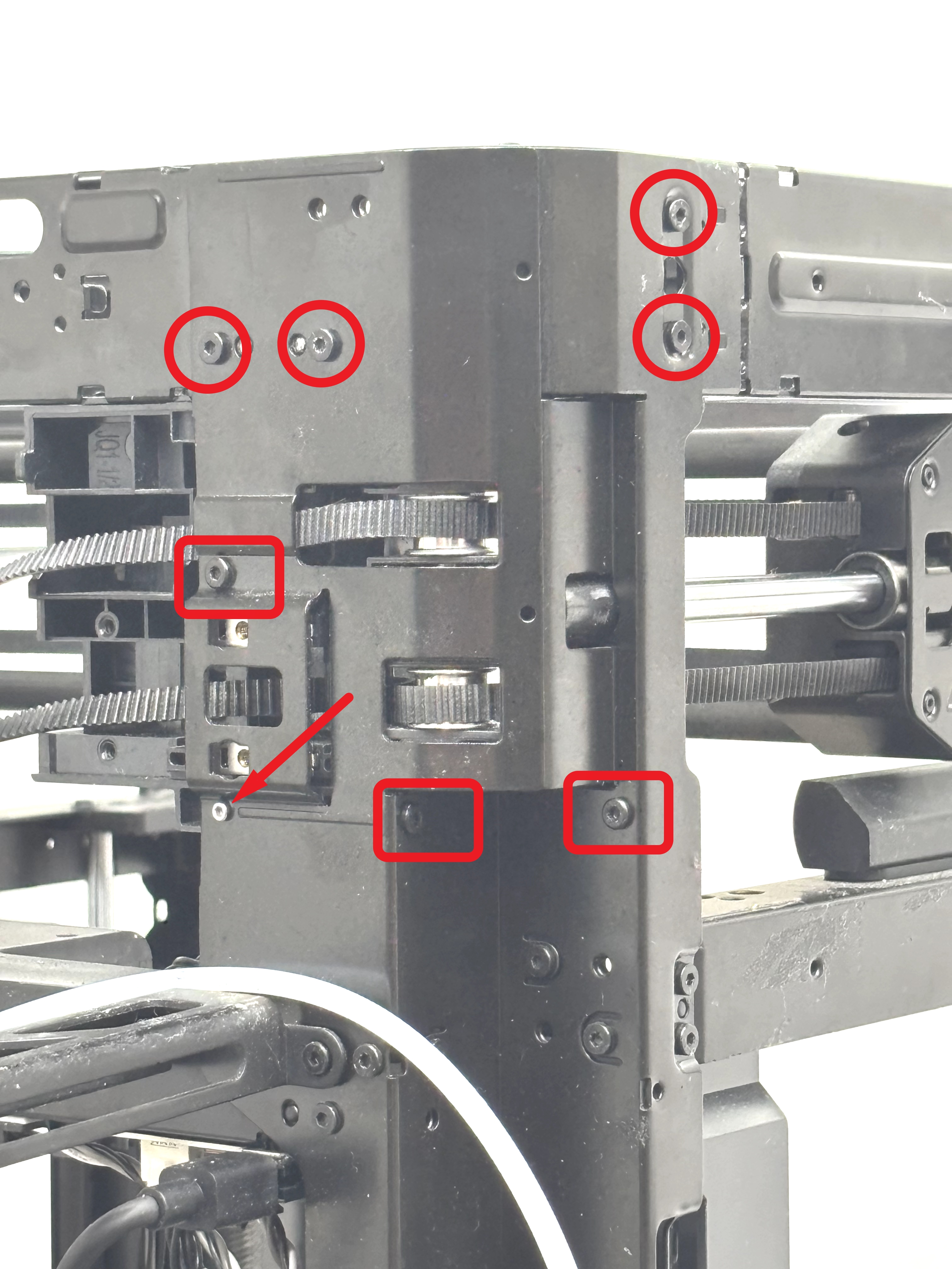
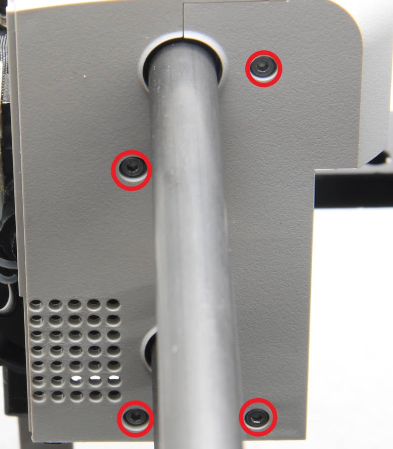
- Remove the screws of the right rear pillar:
Use an H2.0 Allen key to remove the 6 circled screws, then use an H2.0 Allen key to remove the 2 squared screws, and use an H1.5 Allen key to remove 1 silver screw marked with an arrow.
If your printer is a P1S, these two screws shown below were removed when the rear and side panels were removed.
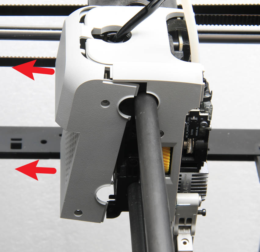
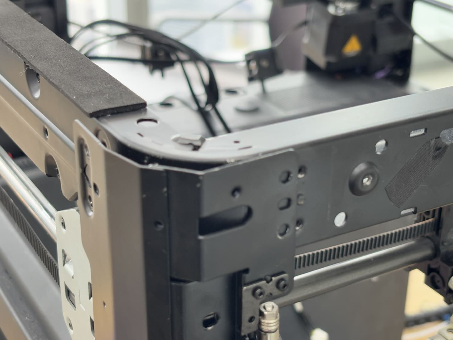
Remove the front frame
It is necessary to break the pillar outward (you can use an H2.0 Allen key to pry it open) to unlock the pins between the frame and the pillar;
Need to break/bridge all four uprights outward.
 |
 |
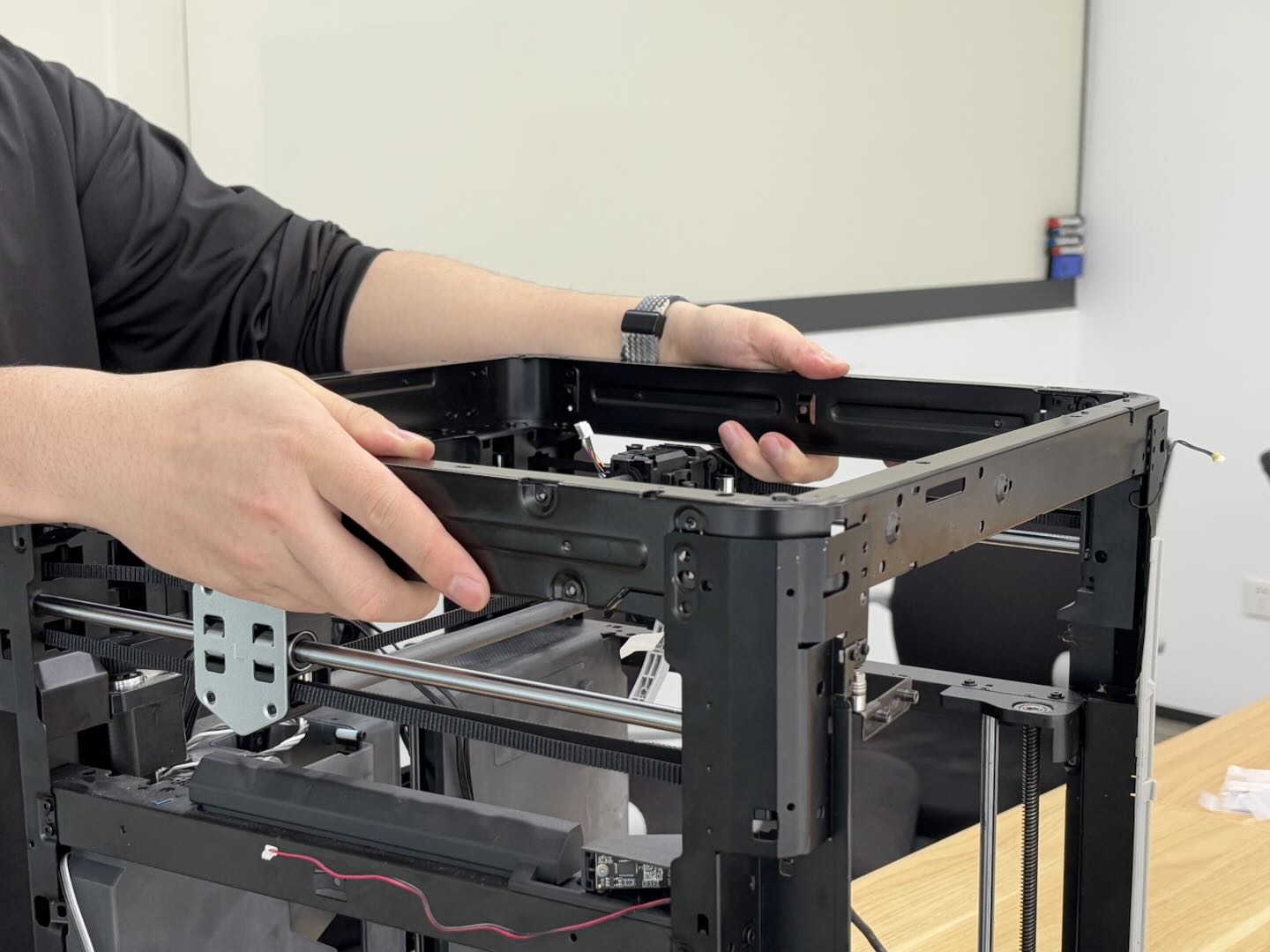
Then remove the X/Y frame by lifting it upward.
 |
 |
¶ Install the core XY movement system
¶ Step 1: Install the core XY movement system
Align the new X/Y frame with the four pillars, then insert the X/Y frame into the printer. Align the protrusions of the X/Y frame with the small holes on the pillars to ensure proper installation. The side of the X/Y frame with the motor bracket is the back, while the side with the screen mounting holes is the front, as shown in the image below:
|
|
|
Note:
- You need to tear the camera cable down a little to see the positioning hole on the left side of the left front pillar.
- After installing the core XY movement system, please check whether the belt can move normally. If it is stuck between the core XY movement system and the pillars, please adjust it in time.
| Left front pillar | Right front pillar | Left rear pillar | Right rear pillar |
|---|---|---|---|
 |
 |
 |
 |
Tighten the left front, right front, left rear, and right rear screws in sequence (pay attention to the circled screws, squared screws, and silver screws).
| Left front pillar | Right front pillar | Left rear pillar | Right rear pillar |
|---|---|---|---|
|
|
|
 |
If your printer is a P1P, you need to tighten these two screws.
¶ Step 2: Install the XY motor and tensioners
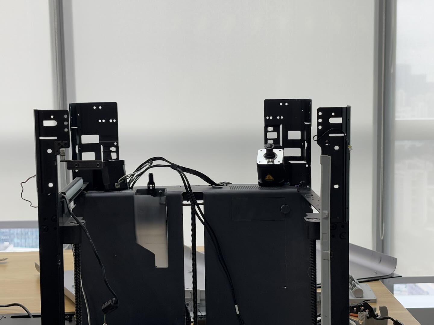
- Install the XY motor
You can reinstall the X/Y motor, which was placed on the lining, onto the motor bracket, and then install the X/Y belt onto the active pulley of the X/Y motor. Afterward, use an H2.0 Allen key to tighten the four screws securing the motor.
You need to insert the 2 screws at the back through the holes in the upper beam, then place them onto the Allen key and use the key to secure the screws in place.
 |
 |
 |
You can refer to the following Wiki for detailed steps on how to replace the XY motor of P1P/P1S: XY motor
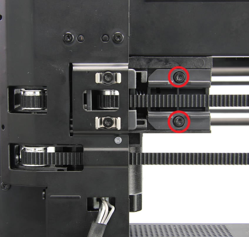
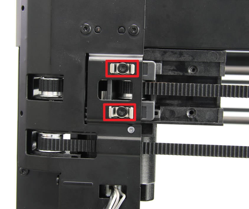
- Install the XY tensioner
Install the XY tensioner in place, attach the 2 limit holders, and loosely screw in the screws for preliminary fixation without tightening them.
Put the spring and tensioner holder in place and tighten the 2 screws using an H2.0 Allen key.
|
|
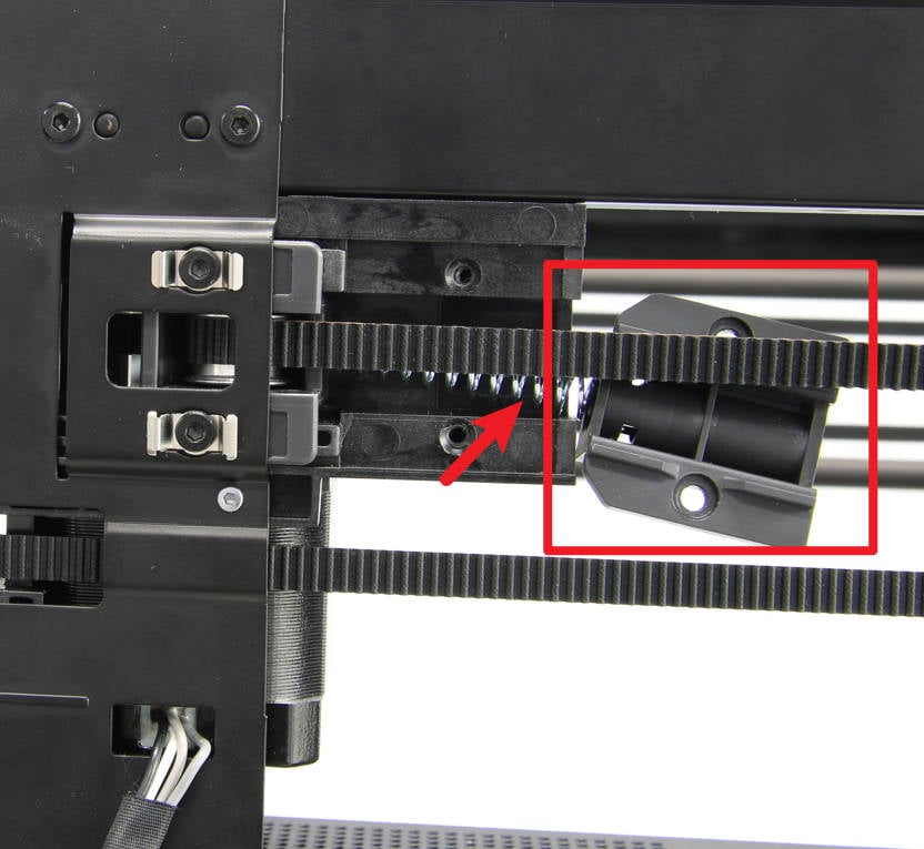
- Tension the XY belt
Use an H2.0 Allen key to loosen the 2 screws on the other XY tensioner, hold the blocks at both ends of the toolhead with both hands and move them forward and backward several times, then stop close to the rear. Use an H2.0 Allen key to tighten the 4 screws on the XY tensioner on both sides.
 |
 |
You can refer to the following Wiki for detailed steps on belt tensioning: Belt tensioning procedure
¶ Step 3: Install the front cover
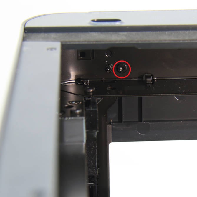
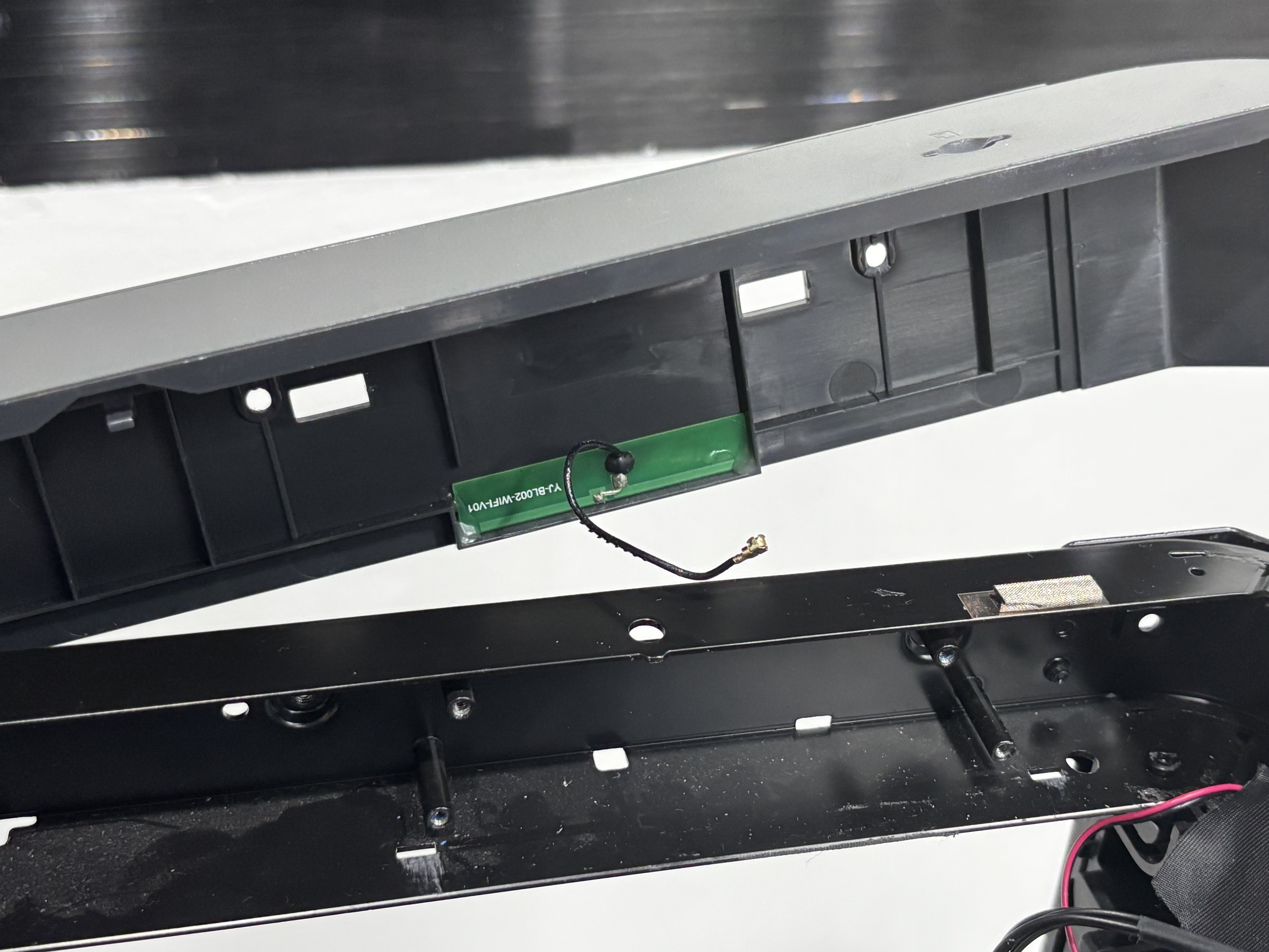
Since the Wifi antenna and the front cover have been removed together, you need to pass the Wifi antenna through the small hole on the core XY movement system before installing the front cover:
There are two small holes on the core XY movement system. Pass the Wifi antenna through the hole on the right side (facing the printer).
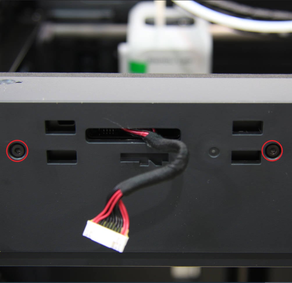
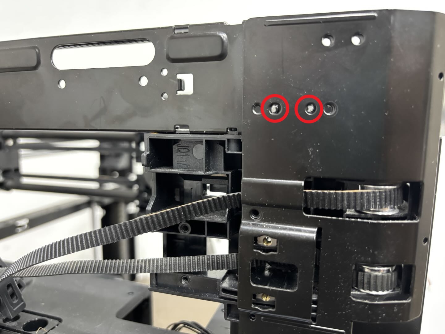
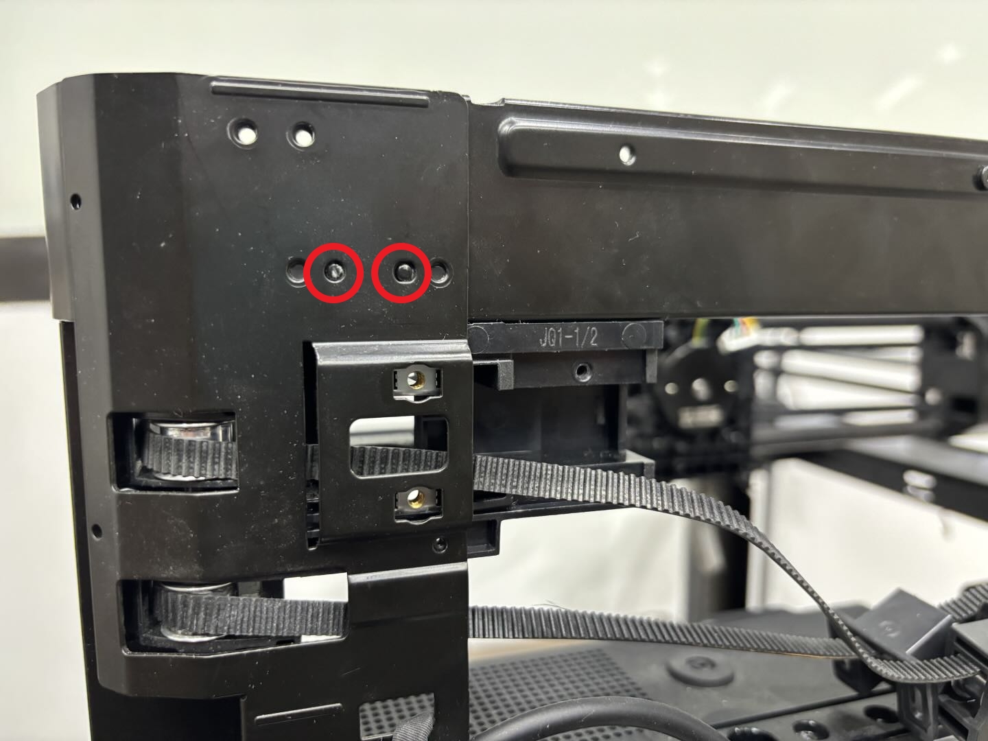
Then align the front cover with the core XY movement system and use an H2.0 Allen key to tighten the 2 outer fixing screws and the 1 inner fixing screw (the screws on the outer and inner sides have different specifications, so pay attention to the difference).
You can refer to the following Wiki for detailed steps on how to replace the front cover of the P1P/P1S:
¶ Step 4: Install the AP board/screen/MC-AP cable
- Install the MC-AP cable and AP board
- MC-AP cable:
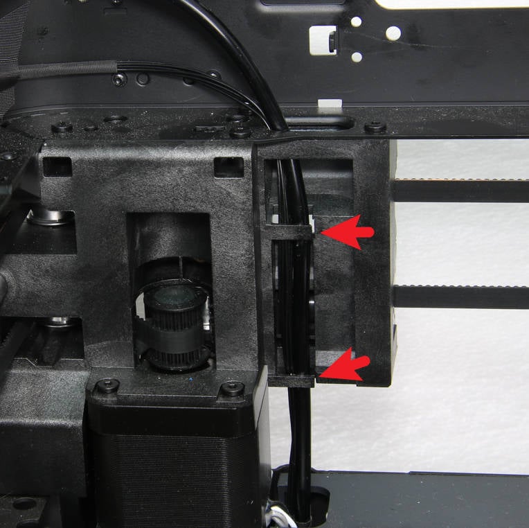
Pass the MC-AP cable through the cable hole on the core XY movement system and press the MC-AP cable into the cable channel. Then connect the other end of the MC-AP cable to the AP board.
Note: The other end of the MC-AP cable has not been disconnected from the MC board.
 |
 |
| Pass through the cable hole and press into the cable channel | Connect to AP board |
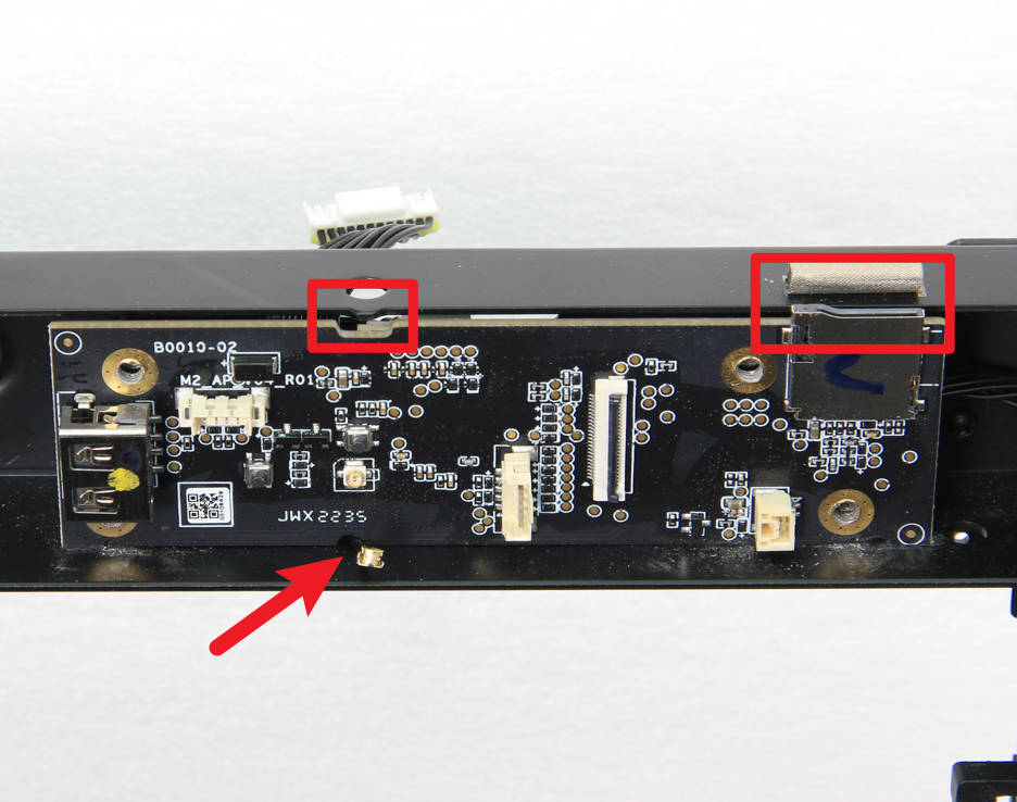
- AP board:
Then install the AP board onto the core XY movement system according to the notch position of the SD card slot, and then tighten the 4 screws with an H2.0 Allen key and connect the Wifi antenna to the AP board:
Be careful to avoid Wifi antenna!
 |
 |
You can refer to the following Wiki for detailed steps on how to replace the MC-AP cable and AP board of P1P/P1S:
- Install the screen
Pass the screen cable through the small hole on the front cover, and then fix the screen to the front cover with the buckle:
 |
 |
You can refer to the following Wiki for detailed steps on how to replace the screen of the P1P/P1S:
¶ Step 5: Install the TH board/extruder/hotend/toolhead cable
- Install the toolhead cable
Pass both ends of the toolhead cable through the cable holes respectively, press the cables into the cable channel, and then connect the toolhead cable to the MC board:
Since the TH board is not installed yet, the other end of the toolhead cable is connected to the TH board in the next step.
 |
|
 |
You can refer to the following Wiki for detailed steps on how to replace the toolhead cable of P1P/P1S.
- Install the TH board assembly
Since the FPC cable is connected to the TH board and extruder connection board, you can first insert the FPC cable into the cable slot. Then, connect the toolhead cables, with the motor interface facing outward. Install the TH board onto the toolhead carriage rear cover, connect the motor to the TH board, and use an H1.5 Allen key to tighten the three screws securing the TH board and the two screws securing the extruder connection board.
 |
|
|
You can refer to the following Wiki for detailed steps on how to replace the TH board assembly of P1P/P1S:
Toolhead Board Replacement Guide
- Install the toolhead middle cover/rear cover
According to the position of the circular cable hole, confirm the installation direction and install the middle cover of the toolhead in place. Then install the rear cover of the toolhead onto the toolhead, and note that there is a buckle on the top. After confirming that the rear cover of the toolhead and the middle cover are buckled in place, tighten the 8 screws in sequence using an H1.5 Allen key.
 |
 |
|
|
You can refer to the following Wiki for detailed steps on how to replace the toolhead middle cover/rear cover of P1P/P1S:
Replace the Toolhead Rear Housing and Middle Housing
- Install the extruder/hotend/toolhead front cover
Install the extruder onto the toolhead and tighten the 3 screws using an H2.0 Allen key; then connect the PTFE tube to the extruder and connect the filament sensor board cable.
|
|
Finally, connect the toolhead front cover cable to the connection board and close the front cover.
 |
 |
You can refer to the following Wiki for detailed steps on how to replace the extruder and hotend of P1P/P1S:
¶ Step 6: Install left/right panels, rear panel and front glass door
Since the P1P does not include the left and right panels and the front glass door, you only need to install the rear panel.
- Install the right panel of P1S
Replace the Right Plastic Panel
- Install the left panel of P1S
Replace the Left Plastic Panel
- Install the rear panel of P1S/P1P
- Install the front glass door of P1S
¶ Calibration
Connect the power, start the printer, and run the device calibration process. If the calibration process passes smoothly, the operation is successful.
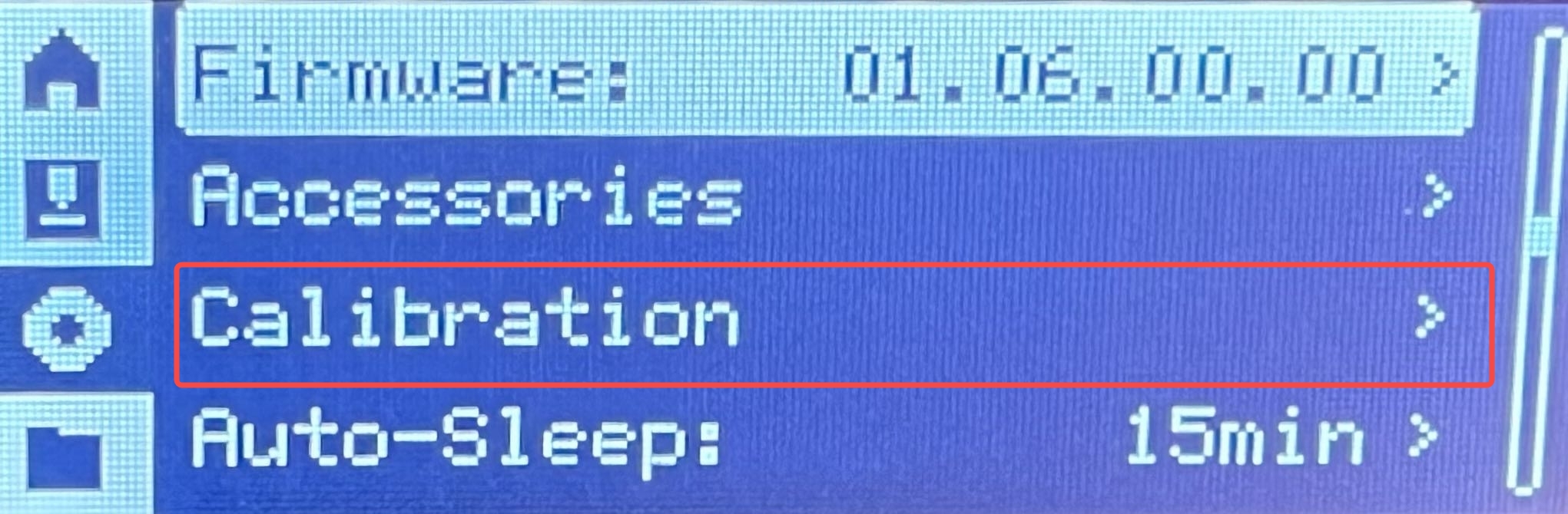
If there is an abnormality, please follow the steps to check whether there is a problem with the assembly. After troubleshooting, run the device self-test again. If the problem persists, please contact the Bambu Lab service team for further assistance.
¶ End Notes
We hope the detailed guide provided has been helpful and informative.
If this guide does not solve your problem, please submit a technical ticket, we will answer your questions and provide assistance.
If you have any suggestions or feedback on this Wiki, please leave a message in the comment area. Thank you for your support and attention!